Proper Installation Steps for Industrial Cable Assemblies
Proper Installation Steps for Industrial Cable Assemblies
Industrial cable assemblies are critical components in manufacturing, energy, automation, and infrastructure systems. Proper installation ensures longevity, safety, and optimal performance. However, incorrect practices can lead to equipment failure, safety hazards, or costly downtime. This guide outlines proven steps for installing industrial cable assemblies, aligned with industry standards like IEC 60204 and NEC Article 400.
1. Pre-Installation Planning
a. Review Specifications
Start by analyzing the cable assembly’s datasheet, including:
- Voltage/current ratings
- Temperature range (e.g., -40°C to 105°C)
- Bend radius (e.g., 8x the cable diameter)
- Chemical/abrasion resistance requirements.
b. Assess the Environment
Identify environmental stressors:
- Temperature extremes (e.g., near furnaces or freezers).
- Exposure to oils, solvents, or moisture.
- Mechanical risks (vibration, abrasion, or crushing).
c. Design Routing Paths
Plan cable routes to avoid:
- Sharp edges or moving machinery.
- High-traffic areas prone to physical damage.
- Parallel runs with high-voltage cables (to prevent EMI).
2. Prepare Tools and Safety Gear
Essential Tools:
- Cable cutters/strippers
- Crimping tools (calibrated for connectors)
- Multimeter/megger for testing
- Cable ties, clamps, and conduit.
Safety Precautions:
- Wear PPE: insulated gloves, safety glasses, and flame-resistant clothing.
- De-energize equipment and use lockout/tagout (LOTO) protocols.
3. Cable Handling and Preparation
a. Avoid Uncoiling Damage
Unroll cables from reels using a “figure-8” method to prevent kinks. Never drag cables across rough surfaces.
b. Cut to Length
Measure twice and cut once, leaving slack (10–15% extra) for future adjustments. Use sharp cutters for clean ends.
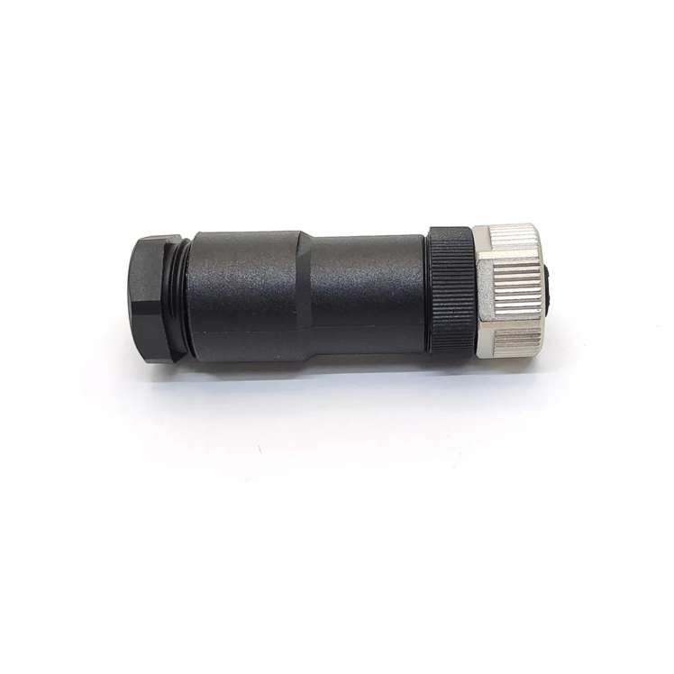
c. Strip and Terminate
- Strip insulation using tools that match the cable’s jacket material (PVC, TPE, etc.).
- Terminate connectors per manufacturer guidelines. For example:
- Use torque screwdrivers for terminal blocks.
- Apply dielectric grease on outdoor connections to prevent corrosion.
4. Routing and Securing Cables
a. Bend Radius Compliance
Maintain the minimum bend radius (e.g., 10x diameter for shielded cables) to avoid conductor or shielding damage.
b. Secure with Clamps/Ties
- Space supports every 12–24 inches for horizontal runs.
- Use abrasion-resistant clamps in high-vibration zones.
c. Separate Signal and Power Cables
Run low-voltage signal cables (e.g., Ethernet, RS-485) at least 12 inches from power lines. Cross them at 90° angles if overlap is unavoidable.
5. Shielding and Grounding
a. EMI/RFI Protection
- Use braided shields or foil tapes for sensitive cables.
- Ground shields at one end only (typically the control panel) to prevent ground loops.
b. Verify Ground Connections
Ensure ground lugs are tight and free of paint/debris. Test continuity between the shield and ground point (<1 Ω resistance).
6. Testing and Validation
a. Continuity Test
Use a multimeter to confirm all conductors are properly connected and free of shorts.
b. Insulation Resistance Test
Apply 500–1000V DC with a megger to verify insulation integrity (>100 MΩ is typical for industrial cables).
c. Functionality Test
Re-energize the system and check for proper operation (e.g., motor rotation, sensor signals).
7. Documentation and Labeling
- Label both ends of each cable with unique IDs matching schematics.
- Update as-built drawings and maintenance logs for future troubleshooting.
8. Post-Installation Maintenance
- Inspect cables quarterly for wear, corrosion, or loose connections.
- Clean connectors with electrical contact cleaner if dust/oil buildup occurs.
Common Mistakes to Avoid
Poor Grounding: Leads to noise interference or electrical hazards.
Ignoring Bend Radius: Causes shield damage and intermittent failures.
Over-tightening Connectors: Strips threads or cracks housings.