Best

Industrial Cable Assemblies factory

Faq|News

Tidal energy is a predictable and clean form of renewable power, but its marine environment—with high salinity, strong currents, and constant vibration—demands cabling systems that go beyond standard industrial specs. This is where custom micro coaxial wire harnessesbecome critical for renewable energy industrial cable assemblies. Standard cables often fail prematurely in tidal farms due to corrosion, water ingress, and flex-fatigue. In contrast, a purpose-built micro coaxial wire harness is engineered to ensure long-term reliability and performance in these harsh conditions. 🌊 Why Tidal Farms Need More Than Standard Cables Tidal farms, or groups of tidal stream generators, are essentially underwater wind farms. They use turbines in fast-moving tidal currents to generate electricity, which is then transmitted to shore via subsea cables and substations. While the resource is predictable, the environment is punishing. Cables and connectors on turbine nacelles, hubs, and seabeds face a combination of challenges: High Salinity & Corrosion:Saltwater is highly corrosive to metals and can degrade standard insulation and jacketing. Dynamic Stress:Tidal flows create continuous, multidirectional movement, leading to fatigue and abrasion on cables and terminations. Pressure & Depth:Subsea installations must withstand high hydrostatic pressure, requiring robust mechanical design. Variable Temperatures:Equipment operates in a wide thermal range, from cold deep water to warmer surface conditions. EMI/EMC Sensitivity:Nearby turbines and power electronics create strong electromagnetic fields that can disrupt data and control signals. Generic industrial or marine cables are rarely designed to handle this specific combination of factors over a 20–30 year asset life. This is why leading renewable energy providers are turning to custom micro coaxial wire harnessesas a core part of their cable management strategy. 🔬 What is a Custom Micro Coaxial Wire Harness? A micro coaxial cable is a very thin coax, often with an outer diameter of just 1 mm or less. It consists of a center conductor, dielectric, shielding, and an outer jacket. When these are integrated into a complete assembly with connectors, strain reliefs, and routing, it becomes a wire harness. Key Characteristics: Miniaturization:Ideal for tight spaces within turbine hubs or nacelles where routing space is extremely limited. High-Frequency Performance:Maintains signal integrity for high-speed data, sensor readings, and control signals, with low attenuation and stable impedance. Superior Shielding:Features multi-layer shielding (foil and braid) to protect against EMI/RFI, which is crucial near power electronics and generators. Mechanical Durability:Built to withstand tight bend radii and constant motion without signal degradation, using high-flex cables and robust connector locks. Environmental Protection:Employs materials resistant to saltwater, UV, and temperature extremes, with optional IP67/IP68-rated sealing for subsea use. In a tidal energy system, these harnesses are used for critical high-speed links, such as: Rotor blade pitch and position sensors Nacelle and hub internal control networks Subsea instrumentation and monitoring systems High-resolution camera and LIDAR data links Communication between turbine controllers and shore 💡 Why Customization is Non-Negotiable Off-the-shelf micro coax cables are designed for controlled environments like labs or consumer electronics. They are not suitable for the scale, complexity, and lifespan of a tidal farm project. 1. Precise Fit & Space Optimization Every turbine platform has unique spatial constraints. Custom harnesses are designed to the exact bend radius, length, and connector orientation required, eliminating unnecessary slack and reducing points of failure. 2. Tailored Electrical Performance Tidal applications often require specific impedance (e.g., 50 Ω or 75 Ω), frequency response, and shielding effectiveness. Custom designs ensure optimal signal integrity by matching the cable, connector, and termination for the application’s specific data rate and EMI environment. 3. Environmental Resilience Standard PVC jackets fail quickly in seawater. Custom harnesses use materials proven in marine environments, such as cross-linked polyolefin (XLPO) or fluoropolymers, with robust jacketing and optional water-blocking tapes or gels for subsea use. 4. Integrated Strain Relief & Mechanical Protection Turbine vibration and cable movement can cause connectors to loosen or cables to fatigue. Custom harnesses integrate strain reliefs, overmolding, and robust backshells to secure the connection and protect it from mechanical stress. 5. Simplified Installation & Maintenance Pre-assembled, labeled, and tested custom harnesses arrive ready to install, significantly reducing on-site labor and the risk of wiring errors. This is a major advantage for projects with dozens of turbines in remote locations. 🛠️ Engineering a Custom Harness for Tidal Energy Designing a reliable custom micro coaxial wire harness involves a structured engineering process: Define Functional Requirements:Determine the signals (video, data, control), data rates, power levels, and operating environment (subsea, splash zone, nacelle). Select the Right Cable:Choose a micro coax with the correct impedance, frequency range, flexibility, and environmental rating. Consider trade-offs between size, attenuation, and flexibility. Choose Robust Connectors:Select miniature RF or coaxial connectors with positive locking mechanisms and high mating cycles. Ensure the connector is rated for the environment or can be sealed. Plan the Routing & Bend Radii:Map the cable path to avoid sharp bends and pinch points. Adhere to the manufacturer’s minimum bend radius to prevent signal loss and mechanical failure. Incorporate Shielding & Grounding:Use multi-layer shielding and ensure a low-impedance ground path. In mixed-signal environments, consider separating analog and digital grounds. Add Mechanical Protection:Include braided sleeves, conduit, or overmolding at stress points. For subsea use, incorporate water-blocking elements. Prototype, Test & Validate:Build and test prototypes for electrical performance (VSWR, attenuation) and mechanical stress (flex, vibration). Perform salt fog, UV, and thermal cycling tests to validate the design. 📈 Linking Reliability to Project Economics Tidal energy projects have high upfront costs, making reliability and low lifecycle costs paramount. Component failures can lead to expensive downtime and specialized vessel mobilization for repairs. A failed micro coaxial harness on a subsea turbine can mean: Loss of critical sensor data or control signals. Unplanned turbine shutdowns. Costly recovery operations, sometimes requiring a crane vessel. By using a custom, application-specific harness, you are making a long-term investment in: Reduced Downtime:Fewer failures mean more uptime and predictable power generation. Lower O&M Costs:Simplified maintenance and fewer emergency call-outs. Extended Asset Life:Properly specified materials resist aging and environmental stress, protecting your investment. In this context, a custom micro coaxial wire harnessis not an optional extra; it is a foundational element for a commercially viable tidal energy project.

More

In industrial settings such as manufacturing plants, oil refineries, automotive production lines, and marine engineering, cable assemblies are often exposed to harsh conditions—constant oil immersion, high temperatures, mechanical abrasion, chemical corrosion, and even extreme pressure. Among these, oil contamination is one of the most damaging factors, as it can degrade insulation, weaken conductors, and ultimately lead to cable failure, causing production downtime, equipment damage, or even safety hazards. Oil resistant industrial cable assemblies are designed to combat these challenges, and their durability in harsh environments is largely determined by the materials used in their construction. From conductors and insulation to jackets and shielding, each component’s material selection plays a critical role in ensuring the cable assembly’s resistance to oil and overall longevity. This article delves into the key materials that make these cable assemblies reliable in oil-rich and harsh industrial environments, explaining their properties, benefits, and applications. 1. Conductive Materials: The Foundation of Reliable Signal and Power Transmission The conductor is the core of any cable assembly, responsible for transmitting electrical signals or power. In oil-resistant industrial applications, conductors must not only offer excellent electrical conductivity but also resist corrosion and degradation when in contact with oil and other harsh substances. The two primary conductive materials used in oil resistant industrial cable assemblies are copper and aluminum, with copper being the preferred choice for most high-demand scenarios. 1.1 Copper Conductors Copper is the gold standard for industrial cable conductors, and for good reason. It boasts exceptional electrical conductivity—second only to silver—ensuring efficient power transmission with minimal energy loss. When it comes to oil resistance, copper’s natural properties, combined with specific plating treatments, make it highly durable in harsh environments. Unplated copper can withstand exposure to most industrial oils (such as mineral oils, hydraulic oils, and synthetic oils) without significant corrosion, as oil acts as a partial barrier against oxygen, reducing oxidation. However, in environments where oil is mixed with moisture or chemicals (e.g., acidic or alkaline substances), copper may be prone to tarnishing or pitting. To address this, copper conductors in oil resistant cable assemblies are often plated with tin, silver, or gold. Tin-plated copper is the most common option for oil-resistant applications. Tin provides an additional layer of protection against corrosion, preventing the copper from reacting with moisture, acids, or other contaminants present in the oil. It also improves the solderability of the conductor, making installation and maintenance easier. Silver-plated copper is used in high-performance applications where higher conductivity, better thermal resistance, and enhanced corrosion resistance are required—such as in high-temperature oil refineries or aerospace industrial settings. Gold-plated copper, though more expensive, offers superior corrosion resistance and is ideal for critical applications where signal integrity must be maintained in extremely harsh, oil-rich environments. 1.2 Aluminum Conductors Aluminum is a more cost-effective alternative to copper, with good electrical conductivity (about 60% that of copper). It is also lighter, making it suitable for applications where weight is a concern. However, aluminum is more prone to corrosion than copper, especially in the presence of oil and moisture. Aluminum oxide, the protective layer formed on aluminum’s surface, can be compromised by certain industrial oils, leading to further oxidation and weakening of the conductor. For this reason, aluminum conductors are rarely used in oil-resistant industrial cable assemblies unless cost is the primary driver and the environment is relatively mild (e.g., low moisture, non-corrosive oils). When used, they are typically coated with a protective layer (such as epoxy or polyurethane) to enhance oil and corrosion resistance. 2. Insulation Materials: Shielding Conductors from Oil and Harsh Elements Insulation materials surround the conductor, preventing electrical short circuits and protecting the conductor from external damage—including oil immersion. For oil resistant industrial cable assemblies, insulation materials must be chemically resistant to a wide range of industrial oils, as well as resistant to high temperatures, abrasion, and chemical corrosion. The most commonly used insulation materials for this purpose are cross-linked polyethylene (XLPE), ethylene propylene rubber (EPR), and fluoropolymers such as polytetrafluoroethylene (PTFE). 2.1 Cross-Linked Polyethylene (XLPE) XLPE is a widely used insulation material in industrial cables due to its excellent balance of performance and cost-effectiveness. It is created by cross-linking polyethylene molecules, which enhances its thermal stability, mechanical strength, and chemical resistance—including oil resistance. XLPE can withstand exposure to mineral oils, hydraulic oils, and most synthetic oils without swelling, cracking, or degrading. It also has a high temperature rating (typically up to 90°C or 125°C for cross-linked versions), making it suitable for use in high-temperature industrial environments such as engine bays or oil refineries. One of the key advantages of XLPE is its flexibility, which makes cable installation easier in tight spaces. It also has good dielectric strength, ensuring reliable insulation even in high-voltage applications. However, XLPE may not be suitable for environments exposed to aggressive chemicals (such as strong acids or bases) in addition to oil. In such cases, more robust materials like fluoropolymers are preferred. 2.2 Ethylene Propylene Rubber (EPR) EPR is a synthetic rubber known for its exceptional resistance to heat, ozone, and chemicals—including oil. It is commonly used in oil resistant industrial cable assemblies that operate in harsh environments with high temperatures (up to 150°C) and exposure to a wide range of oils, including mineral oils, synthetic oils, and even some aggressive hydraulic fluids. EPR’s chemical structure makes it highly resistant to swelling and degradation when immersed in oil, ensuring long-term insulation performance. EPR also has excellent mechanical flexibility and resistance to abrasion, making it suitable for applications where the cable is subject to frequent bending or physical contact with rough surfaces (e.g., in conveyor systems or heavy machinery). Additionally, EPR is resistant to ozone and weathering, making it suitable for both indoor and outdoor oil-resistant applications. However, EPR is more expensive than XLPE, which may limit its use in cost-sensitive projects. 2.3 Fluoropolymers (PTFE, FEP, PFA) Fluoropolymers are a family of high-performance plastics known for their exceptional chemical resistance, thermal stability, and oil resistance. The most commonly used fluoropolymers in oil resistant industrial cable assemblies are polytetrafluoroethylene (PTFE), fluorinated ethylene propylene (FEP), and perfluoroalkoxy alkane (PFA). These materials are ideal for applications where the cable is exposed to aggressive oils, chemicals, or extreme temperatures. PTFE, also known by the brand name Teflon, is perhaps the most well-known fluoropolymer. It has an extremely low coefficient of friction, excellent dielectric properties, and is resistant to almost all industrial chemicals and oils—including strong acids, bases, and solvents. PTFE can withstand temperatures up to 260°C, making it suitable for use in high-temperature oil refineries, chemical processing plants, and aerospace applications. However, PTFE is relatively stiff, which can make cable installation more challenging, and it is more expensive than XLPE or EPR. FEP is a modified version of PTFE that offers better flexibility and processability while maintaining similar chemical and oil resistance. It has a temperature rating of up to 200°C and is often used in oil resistant cables that require flexibility (e.g., in robotic arms or moving machinery). PFA, another fluoropolymer, combines the flexibility of FEP with the high-temperature resistance of PTFE, making it suitable for extreme environments where both flexibility and resistance to oil and heat are required. 3. Jacket Materials: The Outer Layer of Protection Against Harsh Environments The jacket is the outermost layer of a cable assembly, providing protection against physical damage, oil immersion, chemical corrosion, and environmental factors such as moisture, UV radiation, and extreme temperatures. For oil resistant industrial cable assemblies, the jacket material must be highly resistant to swelling, cracking, and degradation when exposed to a wide range of industrial oils. The most commonly used jacket materials for this purpose are polyurethane (PU), neoprene (polychloroprene), and PVC (polyvinyl chloride) – though PVC is only suitable for mild oil environments. 3.1 Polyurethane (PU) Polyurethane is a popular jacket material for oil resistant industrial cable assemblies due to its exceptional oil resistance, mechanical strength, and flexibility. It is resistant to most industrial oils, including mineral oils, hydraulic oils, and synthetic oils, and does not swell or degrade when immersed in these substances. PU also has excellent abrasion resistance, making it ideal for applications where the cable is subject to frequent contact with rough surfaces (e.g., in manufacturing plants, construction sites, or marine environments). PU has a wide temperature range (typically from -40°C to 90°C), making it suitable for use in both extreme cold and moderate heat environments. It also has good resistance to UV radiation and weathering, making it suitable for outdoor.

More

In the complex and demanding landscape of industrial operations, cable assemblies serve as the “neural network” that ensures the seamless transmission of power and signals. Among the various materials used for cable sheathing and insulation, Polyurethane (PUR) and Polyvinyl Chloride (PVC) are two of the most common options. While PVC has long been a staple due to its cost-effectiveness and basic protective properties, PUR industrial cable assemblies have emerged as a superior choice for high-performance applications. This article delves into the core advantages of PUR industrial cable assemblies over their PVC counterparts, highlighting why they are increasingly preferred in environments where reliability, durability, and long-term performance are non-negotiable. 1. Superior Mechanical Durability: Withstanding Wear, Tear, and Flexing One of the most significant advantages of PUR industrial cable assemblies lies in their exceptional mechanical properties, which far outperform PVC in harsh industrial settings where cables are subjected to frequent movement, friction, and physical stress. Abrasion resistance is a standout feature of PUR materials. Laboratory tests and real-world applications have consistently shown that PUR sheathing has an abrasion resistance 3 to 5 times higher than that of standard PVC cables, and 2 to 3 times higher than rubber cables. This means that in scenarios where cables are dragged across rough surfaces, routed through metal conduits, or used in drag chain systems, PUR cable assemblies maintain their structural integrity far longer. For example, in automotive manufacturing plants where robotic arms move continuously, PVC cables often show signs of sheath damage within 3 to 6 months, requiring frequent replacement. In contrast, PUR cable assemblies in the same environment can last 2 to 4 years, significantly reducing downtime and maintenance costs. Flexibility and bend resistance are another area where PUR outshines PVC. PUR industrial cable assemblies, when paired with finely stranded copper conductors (Class 6 or higher), boast a minimum bend radius as low as 5 times the cable diameter, compared to 8 to 10 times for PVC cables. This enhanced flexibility allows PUR cables to withstand millions of bending cycles without conductor breakage, making them ideal for dynamic applications such as robotic arms, automated production lines, and mobile industrial equipment. For instance, the EcoFlex®️ PUR cable from Alpha Wire can achieve over 8 million flex cycles in tough conditions, a performance that PVC cables simply cannot match. PUR also offers superior tensile strength and compression resistance. The inherent elasticity of PUR materials, combined with optional aramid yarn or steel wire reinforcement layers, enables these cable assemblies to withstand mechanical impacts, extrusion, and suspension tension. This is particularly valuable in heavy machinery, mining equipment, and construction sites where cables are often exposed to accidental impacts or constant tension. PVC cables, by comparison, are more rigid and prone to cracking or breaking under such physical stresses. 2. Exceptional Environmental Adaptability: Thriving in Extreme Conditions Industrial environments are rarely ideal, with extreme temperatures, harsh weather, moisture, and UV radiation posing constant threats to cable performance. PUR industrial cable assemblies excel in these challenging conditions, offering far broader environmental adaptability than PVC alternatives. Temperature tolerance is a key strength of PUR. These cables can operate reliably in a wide temperature range, typically from -40℃ to +105℃, with some specialized models capable of withstanding -50℃ to +90℃ in static conditions and -40℃ to +80℃ in dynamic applications. In extreme cold, such as in冷链 warehouses or outdoor winter applications, PVC cables become brittle and prone to cracking when bent, while PUR cables remain flexible and functional. Conversely, in high-temperature environments like metallurgical workshops or near industrial ovens, PVC insulation tends to soften and degrade as plasticizers volatilize, leading to reduced insulation resistance and potential short circuits. PUR, however, maintains its structural stability and insulation properties even at elevated temperatures, ensuring consistent performance. UV and weather resistance are another advantage of PUR. PUR sheathing is formulated with anti-UV and anti-ozone additives, allowing it to withstand long-term outdoor exposure to sunlight, rain, and temperature fluctuations without aging, cracking, or discoloration. This makes PUR cable assemblies ideal for outdoor applications such as wind power, photovoltaic systems, and port machinery. PVC cables, on the other hand, are susceptible to UV degradation, with their sheathing often becoming brittle and cracking after just one year of outdoor use. Moisture and water resistance are also superior in PUR cables. Through advanced sealing processes, PUR industrial cable assemblies can achieve IP67 or IP68 waterproof ratings, enabling them to withstand short-term submersion or continuous exposure to humid environments without hydrolysis. This is critical in applications such as food processing facilities with high-pressure washing, marine equipment, and underground engineering. While some PVC cables offer basic water resistance, they are more prone to water ingress over time, especially in harsh or long-term wet conditions. 3. Enhanced Chemical Stability: Resisting Corrosive Substances Industrial environments often expose cables to a variety of corrosive substances, including oils, greases, solvents, acids, and alkalis. PUR industrial cable assemblies demonstrate exceptional chemical resistance, making them far more suitable for these applications than PVC cables. Oil resistance is a particularly notable feature of PUR. Unlike PVC, which can swell, soften, and crack when exposed to mineral oils, hydraulic oils, or cutting fluids, PUR sheathing remains stable even after prolonged immersion. Laboratory tests show that PUR cables immersed in 10# mechanical oil, 32# hydraulic oil, or crude oil for 500 hours exhibit a volume change rate of less than 5%, compared to over 20% for PVC cables. This makes PUR cable assemblies the ideal choice for automotive manufacturing, machine tool operations, and oilfield applications where oil exposure is inevitable. In contrast, PVC cables in these environments often fail within 1 to 2 months, leading to costly downtime and replacement. PUR also offers better resistance to industrial solvents, weak acids, and weak alkalis. In chemical plants, pharmaceutical facilities, and food processing environments where cleaning agents or corrosive gases are present, PUR cables maintain their performance and structural integrity. While PVC cables can withstand some common cleaning agents, they are not resistant to strong solvents or prolonged exposure to corrosive substances. For example, in steel酸洗 workshops, PVC cables quickly degrade due to exposure to hydrochloric acid, while PUR cables remain unaffected. Additionally, PUR is resistant to mold and mildew growth, a critical advantage in humid, enclosed environments such as underground tunnels, ship cabins, and tropical industrial facilities. PVC cables, by comparison, can promote mold growth in such conditions, leading to sheath degradation and potential electrical hazards. 4. Improved Safety and Environmental Sustainability In today’s industrial landscape, safety and sustainability are increasingly important considerations. PUR industrial cable assemblies offer significant advantages over PVC in both areas. From a safety perspective, PUR is a halogen-free material. Unlike PVC, which contains halogens and releases toxic gases (such as chlorine) and dense smoke when burned, PUR cables produce minimal smoke and no toxic halogen gases in fire situations. This makes them compliant with strict European Union regulations requiring low-smoke, halogen-free (LSZH) cable materials, reducing the risk of harm to personnel and equipment in the event of a fire. PVC cables, by contrast, pose a significant health hazard in fire scenarios due to their toxic emissions. In terms of environmental sustainability, PUR’s exceptional durability translates to less waste. Since PUR cable assemblies have a much longer lifespan than PVC, they need to be replaced far less frequently, reducing the environmental impact of cable production and disposal. Additionally, many PUR materials are recyclable, further enhancing their sustainability credentials. PVC, on the other hand, is less durable and more difficult to recycle, contributing to greater environmental waste. 5. Greater Application Versatility and Customization PUR industrial cable assemblies offer greater versatility and customization options than PVC, making them suitable for a wider range of industrial applications. PUR cables can be customized into various types, including control cables, power cables, drag chain cables, and underwater cables. They are available in single-core or multi-core configurations, with or without shielding layers, and can be reinforced with aramid yarn or steel wire to meet specific application requirements. This flexibility allows PUR cable assemblies to be tailored to the unique needs of industries such as automation, robotics, marine, medical, and oil and gas. For example, multi-core PUR cables are ideal for complex wiring systems in industrial machinery, as they can transmit multiple signals simultaneously, reducing the need for multiple individual cables and simplifying installation. PUR’s lightweight and flexible nature also makes installation easier, particularly in tight spaces or high-altitude applications. Compared to rubber cables with similar performance, PUR cables are lighter and more maneuverable, reducing labor costs and installation time. PVC cab.

More

In the global industrial supply chain, the European Union (EU) market stands out as a high-standard, high-value arena that demands strict compliance with safety, health, and environmental regulations. For manufacturers and suppliers of industrial connectivity solutions, CE certified industrial cable assemblies are not just a product specification but a mandatory “passport” to enter and thrive in this market. But what exactly are CE certified industrial cable assemblies, and why do they hold such decisive importance for EU market access? This article will delve into these core questions, unpacking the technical connotations, certification essentials, and market value of these critical industrial components. What Are CE Certified Industrial Cable Assemblies? To understand CE certified industrial cable assemblies, we first need to break down the two core components of the term: “industrial cable assemblies” and the “CE mark.” Industrial cable assemblies refer to integrated connectivity solutions composed of cables (power, control, signal, or specialty cables) and connectors, tailored for industrial environments. Unlike standard consumer cables, these assemblies are designed to withstand harsh conditions such as extreme temperatures, mechanical stress, electromagnetic interference (EMI), chemical corrosion, and heavy vibration. They serve as the “nervous system” and “circulatory system” of industrial operations, facilitating reliable power transmission, precise control signal delivery, and high-speed data communication in applications ranging from factory automation and robotics to renewable energy plants and marine engineering. The CE mark, derived from the French phrase “Conformité Européenne,” is a mandatory certification mark indicating that a product complies with the essential requirements of relevant EU directives. For industrial cable assemblies, the key applicable directives include the Low Voltage Directive (LVD 2014/35/EU) and the Electromagnetic Compatibility Directive (EMC 2014/30/EU). In specific scenarios—such as construction-related installations or environmentally sensitive areas—they may also need to comply with additional directives like the Construction Products Regulation (CPR) and the Restriction of Hazardous Substances (RoHS 2.0) Directive. Put simply, CE certified industrial cable assemblies are industrial connectivity products that have undergone rigorous testing and evaluation to meet the EU’s strict safety, electromagnetic compatibility, and (where applicable) environmental and construction safety standards. They are accompanied by a complete technical file and a Declaration of Conformity (DoC), formally signed by the manufacturer or authorized representative, confirming their compliance with all relevant EU regulations. The certification process for these assemblies is not a one-size-fits-all formality. It involves a systematic assessment covering multiple aspects: Design and Material Compliance: Ensuring that conductors (e.g., high-purity copper meeting EN 60228 standards), insulation materials (PVC, XLPE, or LSZH), and outer sheaths are selected to meet specific performance requirements—such as flame resistance (per EN 60332 series), temperature tolerance (-40℃ to 125℃ or higher), and chemical resistance. Electrical Safety Testing: Verifying compliance with LVD requirements, including insulation resistance, voltage withstand capacity, and current-carrying capacity, to prevent electrical hazards such as electric shock and short-circuit fires. EMC Performance Testing: Ensuring that the assemblies do not emit excessive electromagnetic radiation (EMI) that could interfere with other equipment, and that they can resist external electromagnetic interference (EMS) to maintain stable performance in industrial environments. Documentation Completion: Compiling a comprehensive technical file containing test reports, design drawings, material specifications, and the Declaration of Conformity—documents that must be retained for at least 10 years after the last product is placed on the market. Why CE Certification Is Essential for EU Market Access For manufacturers aiming to enter the EU market—including the 27 EU member states and the European Economic Area (EEA) countries like Norway, Iceland, and Liechtenstein—CE certification for industrial cable assemblies is not an option but a legal obligation. Beyond compliance, it also addresses critical commercial, safety, and reputational needs. Below are the key reasons why CE certification is indispensable: 1. Legal Compliance: Avoid Severe Sanctions and Market Exclusion EU legislation explicitly mandates that any product falling within the scope of applicable directives (such as LVD and EMC) must bear the CE mark before being placed on the EU market. Industrial cable assemblies, which operate within the low-voltage range (50V-1000V AC, 75V-1500V DC) and interact with other electrical equipment, are strictly subject to these directives. Non-compliant products face severe consequences: Customs authorities may seize shipments, preventing them from entering the EU market. Additionally, manufacturers and importers risk heavy fines (which can reach millions of euros in some member states), product recalls, and even temporary or permanent bans on market access. In extreme cases, company executives may face criminal liability for persistent non-compliance. For example, a 2025 case in Germany saw a supplier fined €2.3 million for distributing uncertified industrial cable assemblies, with all affected products recalled and destroyed. The CE mark also serves as a legal shield for businesses. In the event of product-related accidents (e.g., fires or equipment failures), the technical file and Declaration of Conformity provide evidence of due diligence, helping to mitigate legal risks and liability claims. 2. Unimpeded Market Circulation: Eliminate Cross-Border Trade Barriers One of the core objectives of the CE mark is to facilitate the free movement of goods within the EU single market. Before the adoption of EU harmonized standards, manufacturers often had to comply with different technical requirements and certification processes for each EU member state, leading to high costs and administrative burdens. CE certification simplifies this process: A single CE mark is recognized across all EU and EEA countries, eliminating the need for redundant national certifications. This means that a CE certified industrial cable assembly manufactured in China, the United States, or any other country can be freely sold and distributed in Germany, France, Italy, and other EU markets without additional testing or approval. For manufacturers, this significantly reduces market entry costs and accelerates time-to-market—a critical advantage in the competitive industrial sector. 3. Safety and Reliability: Meet Industrial Environment Demands Industrial environments are inherently harsh, and the failure of a cable assembly can lead to catastrophic consequences—from production downtime and equipment damage to worker injuries and fires. EU directives and harmonized standards (such as EN 50525, EN 60332, and EN 55011) set strict requirements for the safety and performance of industrial cable assemblies, ensuring they can withstand the rigors of industrial use. For example, flame resistance testing per EN 60332 ensures that cable assemblies do not contribute to the rapid spread of fires. In construction-related applications, the CPR further classifies cables based on their fire performance, ensuring they meet the safety requirements of buildings such as factories, hospitals, and high-rises. A study by the European Fire Safety Alliance (EuroFSA) found that non-compliant cables can accelerate fire propagation, leading to flashovers in as little as 7-8 minutes and endangering evacuation routes. In contrast, CE certified cables with high fire performance ratings slow fire spread, providing critical extra time for evacuation and emergency response. CE certification also guarantees consistent quality through strict production control requirements. Manufacturers must adhere to ISO 9001 or other relevant quality management systems, ensuring that every batch of cable assemblies meets the same high standards. This reliability is particularly important for critical applications such as renewable energy (solar and wind power plants), industrial automation (robots and PLC systems), and medical equipment—where component failure can have far-reaching economic and safety implications. 4. Brand Reputation and Customer Trust: Win Business Partnerships In the industrial sector, trust is the foundation of long-term business relationships. Distributors, wholesalers, and end-users—such as factory operators and equipment manufacturers—prioritize CE certified products because they signal a commitment to safety, quality, and compliance. Many large industrial buyers explicitly require CE certification in their procurement contracts. For example, major automotive manufacturers like Volkswagen and BMW, and industrial automation companies like Siemens and ABB, only source CE certified components to ensure the reliability of their own products. A non-compliant cable assembly can lead to the cancellation of business partnerships, loss of repeat orders, and lasting damage to a brand’s reputation. Conversely, CE certification serves as a powerful marketing tool, demonstrating a manufacturer’s professionalism and commitment to meeting global standards—and helping to attract new customers in the EU market. 5. Environmental Compliance: Align with EU Green Policies In recent years, the EU has strengthened its focus on environmental protection, with directives like RoHS 2.0 restricting the use of hazardous substances (such as lead, mercury, and cadmium) in electrical and electronic equipment. CE certified .

More

In the complex ecosystem of industrial operations, electrical systems serve as the backbone that powers machinery, transmits critical data, and ensures seamless coordination between components. Among the countless elements that constitute these systems, industrial cable assemblies stand out as unsung heroes—quietly facilitating the flow of electricity and signals while withstanding harsh operating conditions. However, not all cable assemblies are created equal. Those bearing the UL certification mark are distinguished by rigorous safety and performance standards that make them indispensable for industrial safety. This article delves into the definition of UL certified industrial cable assemblies, the rigorous certification process they undergo, and the pivotal role they play in safeguarding industrial environments, personnel, and assets. What Are UL Certified Industrial Cable Assemblies? To understand UL certified industrial cable assemblies, we first need to break down the key components of the term. Let’s start with the basics: an industrial cable assembly refers to a prefabricated unit consisting of one or more cables, connectors, and other components (such as terminals, sleeves, or shields) that are assembled to perform specific electrical functions in industrial settings. These assemblies are designed to withstand the unique challenges of industrial environments, including extreme temperatures, mechanical stress, chemical exposure, vibration, and electromagnetic interference (EMI). The “UL certification” component is what elevates these assemblies beyond standard products. UL, formerly known as Underwriters Laboratories and now rebranded as UL Solutions, is a globally recognized independent safety science organization founded in 1894. Its core mission is to develop safety standards, test products against these standards, and certify that they meet rigorous requirements for safety, performance, and environmental sustainability. A UL certified industrial cable assembly is therefore one that has successfully passed UL’s comprehensive testing and evaluation processes, demonstrating compliance with relevant UL standards and national/international electrical codes. Notably, UL certification is not a one-size-fits-all designation. Different industrial applications require cable assemblies that adhere to specific UL standards tailored to their use cases. For example: UL 2237: Applies to multi-point interconnection power cable assemblies used with industrial machinery, covering system voltages up to 1,000V and specifying requirements for indoor use, current ratings, and short-circuit current tolerance.UL 2238: Focuses on cable assemblies and accessories for industrial control and signal distribution, including those used in remote control circuits, sensor connections, and actuator interconnections, with ratings up to 60A and 600V.UL 2556: A broader standard covering general cable assemblies, including fixed-installation and portable types, with detailed requirements for materials, design, electrical performance, and testing procedures.UL 44: Specifies safety requirements for insulated and uninsulated power cables used in industrial facilities, ensuring fire resistance, insulation integrity, and mechanical strength. These standards ensure that UL certified industrial cable assemblies are not just generic components but are engineered and tested to perform reliably in their intended industrial environments. The Rigorous Process of UL Certification for Industrial Cable Assemblies UL certification is not an easy achievement—it requires manufacturers to navigate a multi-stage process that leaves no room for compromise. This rigorous process is designed to ensure that certified products consistently meet safety and performance standards, both at the time of certification and throughout their production lifecycle. 1. Standard Alignment and Product Evaluation The certification process begins with manufacturers identifying the appropriate UL standard for their industrial cable assembly based on its intended application. Once the standard is determined, the manufacturer submits detailed product specifications, design drawings, and material information to UL for initial evaluation. This step ensures that the product’s design and materials are inherently capable of meeting the standard’s requirements before any physical testing begins. 2. Comprehensive Testing Testing is the cornerstone of UL certification, and it covers a wide range of performance and safety criteria tailored to industrial cable assemblies. Key tests include:Electrical Safety Testing: This includes insulation resistance testing, dielectric strength testing, and current-carrying capacity evaluations to ensure the assembly can handle its rated voltage and current without short-circuiting, leaking current, or overheating.Fire Resistance Testing: Industrial environments are at risk of fires, so UL tests cable assemblies for flame spread, smoke density, and toxic gas emissions. Standards like UL 94 establish flame ratings, ensuring that certified assemblies can slow or prevent fire spread, a critical factor in protecting personnel and minimizing property damage. For example, plenum-rated (CMP) and riser-rated (CMR) cables undergo specialized fire tests to ensure they are safe for use in air-handling spaces and vertical shafts, respectively.Mechanical Strength Testing: Industrial cable assemblies are often subjected to bending, pulling, vibration, and impact. UL tests evaluate the assembly’s ability to withstand these stresses without compromising its electrical performance or structural integrity. For instance, vibration testing ensures that connectors remain secure and wires do not break under the constant motion of industrial machinery.Environmental Resistance Testing: This includes tests for temperature tolerance (both high and low), resistance to chemicals (such as oils, solvents, and corrosive substances common in industrial settings), and resistance to UV radiation for outdoor applications. For example, UL 4703 covers光伏 (photovoltaic) cables used in renewable energy systems, requiring them to withstand extreme outdoor conditions.Short-Circuit Current Rating (SCCR) Testing: This test evaluates the assembly’s ability to withstand short-circuit conditions without catastrophic failure, ensuring it does not contribute to the escalation of electrical faults. 3. Factory Audits and Continuous Oversight Unlike some certification processes that end with product testing, UL’s certification includes ongoing factory audits. After a product is certified, UL conducts regular inspections of the manufacturer’s facilities to ensure that production processes remain consistent with the tested samples and that all products continue to meet the standard’s requirements. This continuous oversight is critical for maintaining the integrity of the UL mark and ensuring that end-users receive reliable, safe products every time. Why UL Certified Industrial Cable Assemblies Matter for Industrial Safety Industrial environments are inherently hazardous, with risks ranging from electrical fires and shocks to equipment failures that can lead to production downtime, property damage, and even loss of life. UL certified industrial cable assemblies address these risks head-on, making them a non-negotiable component for safe industrial operations. Below are the key reasons why they matter: 1. Mitigating Fire and Electrical Shock Risks Electrical fires and shocks are among the most common and devastating hazards in industrial settings. Faulty cable assemblies—such as those with substandard insulation, poor connector design, or inadequate current-carrying capacity—are a major cause of these incidents. UL certified cable assemblies are rigorously tested to prevent such failures. For example, insulation resistance testing ensures that the insulation material does not degrade or leak current, reducing the risk of short-circuits and electric shocks. Fire resistance testing ensures that in the event of a fire, the assembly does not accelerate the spread of flames or release excessive toxic smoke, giving personnel more time to evacuate and minimizing damage to equipment and facilities. A 2018 fire at a data center in Ohio demonstrated the value of UL-listed cables: plenum-rated UL certified cables slowed smoke spread, enabling faster evacuation and reducing equipment damage significantly. 2. Ensuring Reliable Performance in Harsh Industrial Environments Industrial operations often take place in harsh conditions that would quickly degrade non-certified cable assemblies. Extreme temperatures in manufacturing plants, vibration from heavy machinery, exposure to oils and chemicals in automotive or petroleum processing facilities, and UV radiation in outdoor renewable energy systems—all of these can cause non-certified cables to fail prematurely. UL certified industrial cable assemblies are designed and tested to withstand these conditions, ensuring consistent performance even in the most challenging environments. For example, UL 2237-certified assemblies for industrial machinery are tested to handle vibration and short-circuit conditions, while UL 4703-certified光伏 cables resist UV radiation and extreme temperature fluctuations. This reliability is critical for preventing unexpected equipment failures that can lead to accidents, production halts, or costly repairs. 3. Ensuring Compliance with Legal and Regulatory Requirements In most countries, including the United States, industrial facilities are required to comply with national electrical codes (NEC) and local regulations to ensure workplace safety. The NEC, developed by the National Fire Protection Association (NFPA), explicitly references UL standards and often requires the use of UL certified electrical components, including cable assemblies. For example, NEC Article 800 mandates the use of UL-listed communicatio.

More

In industrial environments such as chemical plants, oil and gas fields, mining sites, and pharmaceutical factories, cable assemblies are often exposed to corrosive chemicals, extreme temperatures, mechanical abrasion, and humid conditions. The durability of chemical resistant industrial cable assemblies in these harsh environments is not accidental but relies on the scientific selection and combination of core materials. From the outer jacket that bears the first wave of environmental erosion to the inner insulation, conductors, and shielding materials, each component’s material properties directly determine the cable’s service life, operational reliability, and safety. This article will delve into the key materials that make chemical resistant industrial cable assemblies durable, analyze their characteristics, and explore their applications in harsh environments. Fluoropolymers: The Gold Standard for Extreme Chemical Resistance When it comes to resisting harsh chemicals, fluoropolymers stand out as the most reliable material group for chemical resistant industrial cable assemblies. Their unique chemical structure—with strong carbon-fluorine bonds—makes them inert to almost all organic and inorganic chemicals, including strong acids,强碱 (strong bases), solvents, and oxidants. Common fluoropolymer materials used in cable assemblies include Polytetrafluoroethylene (PTFE), Fluorinated Ethylene Propylene (FEP), Perfluoroalkoxy (PFA), and Ethylene-Tetrafluoroethylene (ETFE), each with distinct properties that suit different application scenarios. PTFE (Polytetrafluoroethylene) PTFE is renowned for its exceptional chemical resistance, often referred to as “the king of plastics” in corrosive environments. It can withstand exposure to almost all chemicals, including hydrofluoric acid, sulfuric acid, and organic solvents, without degradation. Additionally, PTFE has an extremely wide temperature range, operating from -75°C to +260°C, making it suitable for high-temperature harsh environments such as chemical reaction vessels and metallurgical processes . In cable assemblies, PTFE is commonly used as insulation material for conductors, especially in applications requiring high-frequency signal transmission, thanks to its low dielectric constant and low loss factor. However, PTFE has limitations: it cannot be melt-extruded and requires special processing methods, which makes it more expensive than other materials. This restricts its widespread use in cost-sensitive projects . FEP (Fluorinated Ethylene Propylene) FEP is a modified fluoropolymer that combines the excellent chemical resistance of PTFE with melt-processability. Like PTFE, it is highly resistant to acids, bases, solvents, and oils, and operates in a temperature range of -75°C to +200°C . The melt-extrusion capability of FEP significantly improves production efficiency and reduces costs, making it a popular choice for cable jackets and insulation in chemical resistant industrial cable assemblies. For example, Amphenol TPC’s Chem-Gard® cable series uses FEP jackets and insulation, which can withstand prolonged immersion in kerosene and other harsh chemicals without swelling or cracking . FEP also has excellent flame retardancy and electrical insulation properties, making it suitable for data communication cables in chemical plants, where it can maintain stable performance while reducing the risk of fire and smoke spread . PFA (Perfluoroalkoxy) PFA further enhances the processability of PTFE while retaining its superior chemical and high-temperature resistance. It can be melt-extruded into thin-walled products, making it ideal for applications where both chemical resistance and flexibility are required. PFA operates in a temperature range similar to PTFE (-75°C to +260°C) and has excellent creep resistance, ensuring long-term dimensional stability in harsh environments . In oil and gas exploration, PFA-insulated cables are used in deep-well data logging systems, where they withstand high temperatures, high pressures, and corrosive gases such as hydrogen sulfide . The combination of processability and performance makes PFA a preferred material for high-end chemical resistant industrial cable assemblies. ETFE (Ethylene-Tetrafluoroethylene Copolymer) ETFE is a copolymer of ethylene and tetrafluoroethylene, offering a balance of chemical resistance, mechanical strength, and processability. It is resistant to most chemicals, including acids, bases, and solvents, and has a temperature range of -60°C to +150°C . Compared to other fluoropolymers, ETFE has higher tensile strength and impact resistance, making it suitable for cable jackets in environments with mechanical abrasion. It is also highly transparent, which facilitates visual inspection of cable integrity. ETFE is widely used in automotive and electronic communication applications, where it provides reliable insulation and chemical protection for thin-walled and high-temperature wires . Polyurethanes (PU/TPU): The Ideal Choice for Mechanical Durability and Chemical Resistance While fluoropolymers excel in chemical and high-temperature resistance, polyurethanes—especially Thermoplastic Polyurethane (TPU)—are favored for their exceptional mechanical properties combined with good chemical resistance. TPU is a versatile material that offers high abrasion resistance, tear strength, and flexibility, making it suitable for cable assemblies that require frequent movement or are exposed to mechanical stress, such as drag chains in automation systems and mobile equipment in mining sites . In terms of chemical resistance, TPU can withstand exposure to oils, greases, and many industrial chemicals, although it is less resistant to strong acids and solvents than fluoropolymers . Lubrizol’s Estane® TPU, for example, is widely used in mining cable jackets, where it provides superior abrasion resistance—with a weight loss of only 20-25 mg after 1,000 cycles of Taber abrasion testing, compared to 222 mg for chlorosulfonated polyethylene and 631 mg for flexible PVC . TPU also has excellent low-temperature flexibility, operating from -50°C to +90°C, and is halogen-free, making it suitable for environments with strict fire safety requirements . BASF’s Elastollan® TPU is another high-performance option, offering hydrolysis resistance, oil resistance, and UV stability, making it ideal for cables in oil rigs, power stations, and outdoor industrial applications . Thermoplastic Elastomers (TPE): Balancing Flexibility and Chemical Resistance Thermoplastic Elastomers (TPE) are a class of materials that combine the flexibility of rubber with the processability of thermoplastics. They are increasingly used in chemical resistant industrial cable assemblies due to their good chemical resistance, wide temperature range, and environmental friendliness. TPE is resistant to oils, lubricants, and many industrial cleaning agents, making it suitable for applications in food processing plants and pharmaceutical factories, where frequent washdowns with chemical cleaners are required . TPE has a temperature range of -50°C to +125°C, which allows it to perform reliably in both low-temperature and moderate-high-temperature environments . Its excellent flexibility and fatigue resistance make it ideal for dynamic applications such as robotic arms and moving conveyor systems, where cables are subjected to repeated bending . Unlike traditional rubber materials, TPE can be recycled, reducing environmental impact. However, TPE’s resistance to strong acids and solvents is lower than that of fluoropolymers, so it is more suitable for moderately corrosive environments. Conductor Materials: Ensuring Electrical Conductivity in Corrosive Environments The conductor is the core component of cable assemblies, responsible for transmitting electrical signals or power. In harsh chemical environments, conductors are at risk of corrosion, which can increase resistance and even cause cable failure. Therefore, the selection of conductor materials is crucial for the durability of chemical resistant industrial cable assemblies. The most common conductor material is copper, which offers excellent electrical conductivity. To enhance corrosion resistance, copper conductors are often tinned or silver-plated. Tinned copper conductors are widely used in chemical resistant cables. The tin plating forms a protective barrier that prevents copper from reacting with corrosive chemicals such as sulfur dioxide and hydrogen sulfide . Amphenol TPC’s Chem-Gard® Profibus high-temperature cable, for example, uses finely stranded tinned copper conductors, which not only resist corrosion but also improve flex-life and reduce conductor fatigue . Silver-plated copper conductors offer even higher corrosion resistance and are suitable for ultra-high-frequency signal transmission applications, such as in aerospace and high-precision instrumentation, although they are more expensive. In some extreme environments, such as high-temperature and high-corrosion areas, nickel-plated copper or nickel conductors may be used. Nickel has excellent high-temperature resistance and corrosion resistance, making it suitable for cables in metallurgical processes and gas turbines. However, nickel’s electrical conductivity is lower than copper, so it is only used in specific high-temperature applications. Shielding Materials: Protecting Signal Integrity in Harsh Environments In industrial environments, cable assemblies are often exposed to electromagnetic interference (EMI) and radio frequency interference (RFI), which can disrupt signal transmission. Shielding materials not only protect against interference but also need to resist chemical corrosion to ensure long-term effectiveness. Common shielding materials for chemical resistant industrial cable assemblies include tinned copper braid, aluminum/polyester foil, and metalized films..

More

In industrial environments where extreme heat is a constant challenge—from steel foundries and glass manufacturing plants to aerospace engine compartments and nuclear power facilities—high temperature industrial cable assemblies are the unsung heroes that ensure reliable electrical signal transmission and power supply. For engineers, procurement specialists, and facility managers, understanding the temperature range these cable assemblies can withstand is not just a matter of technical curiosity but a critical factor in ensuring operational safety, system reliability, and long-term cost-effectiveness. This article delves into the typical temperature ranges of high temperature industrial cable assemblies, the materials that determine their heat resistance, and how application-specific factors influence their performance under extreme thermal conditions. The Basic Temperature Classification of High Temperature Industrial Cable Assemblies Unlike standard commercial cables that are designed for ambient temperatures up to 75°C or 90°C, high temperature industrial cable assemblies are engineered to operate in significantly hotter environments. While there is no universal “one-size-fits-all” temperature rating, the industry generally classifies these cables based on their maximum continuous operating temperature (MCO T)—the highest temperature at which the cable can function reliably for an extended period (typically 20,000 hours or more) without significant degradation of its insulation or sheath materials. The most common temperature ratings for high temperature industrial cable assemblies fall into several key ranges: 125°C to 180°C (257°F to 356°F): This is the entry-level range for high temperature cables. Cables in this category are widely used in industrial settings where moderate heat is present, such as automotive engine bays, plastic processing equipment (injection molding machines), and general industrial control systems. Silicone rubber-insulated cables are typical representatives of this range, with many rated for continuous operation at 180°C and capable of withstanding short-term peaks up to 200°C . 200°C to 260°C (392°F to 500°F): Cables in this range are designed for more demanding industrial environments. Fluoropolymer materials like PTFE (polytetrafluoroethylene), FEP, and PFA are the primary insulators here, offering excellent heat resistance along with chemical inertness. These cables are essential in aerospace applications, chemical processing plants (distillation towers, reaction vessels), and high-temperature sensor systems. For example, PTFE-insulated cables can maintain stable performance at 260°C continuously, making them suitable for use in military and aerospace electronic equipment . 280°C to 450°C (536°F to 842°F): This range caters to extreme industrial heat environments, such as metallurgical processes (steel smelting, aluminum casting) and glass manufacturing furnaces. Cables here often use composite insulation materials combined with nickel or nickel-plated copper conductors, which offer superior heat resistance compared to standard copper. Some specialized cables in this range, such as those with ceramic fiber or fiberglass braiding, can withstand short-term temperature spikes up to 500°C . 450°C and Above (842°F and Above): Reserved for the harshest thermal environments, these cables are engineered for applications like high-temperature furnaces, nuclear reactor peripherals, and rocket propulsion systems. Mineral-insulated cables (MICC) with氧化镁 insulation and stainless steel sheaths are typical in this category, with some capable of continuous operation at 700°C and short-term exposure to temperatures up to 1000°C. For instance, stainless steel-jacketed cables can withstand temperatures ranging from -70°C to 760°C, making them ideal for use with high-temperature sensors in extreme industrial settings . Key Materials That Determine Temperature Resistance The temperature range of a high temperature industrial cable assembly is primarily determined by the materials used in its conductor, insulation, and sheath. Each component plays a crucial role in ensuring the cable’s overall heat resistance and performance: 1. Conductors While copper is the most common conductor material due to its excellent electrical conductivity, pure copper can soften and lose mechanical strength at temperatures above 200°C. For higher temperature applications, nickel-plated copper or pure nickel conductors are preferred. Nickel has a higher melting point (1455°C) than copper (1085°C) and retains its strength at elevated temperatures. In extreme cases, silver-plated conductors may be used for their superior conductivity and heat resistance, though they come with a higher cost. For example, cables designed for 450°C operation often use nickel or nickel-plated copper conductors to ensure stable current transmission . 2. Insulation Materials Insulation is the most critical component in determining a cable’s temperature rating, as it prevents short circuits and protects the conductor from environmental damage. Common high-temperature insulation materials include: Silicone Rubber: Rated for 150°C to 180°C continuous operation, silicone rubber offers excellent flexibility and resistance to ozone and weathering. It is widely used in industrial control cables and automotive applications . Fluoropolymers (PTFE, FEP, PFA): PTFE and PFA are rated for 260°C, while FEP is rated for 200°C. These materials are chemically inert, non-flammable, and suitable for harsh environments like chemical processing and aerospace . Glass Mica Tape: Used in cables rated for 250°C to 450°C, glass mica tape offers excellent heat resistance and is often combined with fiberglass braiding for added protection. It is commonly found in metallurgical and high-temperature furnace applications . Ceramic Fiber: Designed for temperatures above 500°C, ceramic fiber insulation is used in extreme environments like rocket engines and high-temperature industrial furnaces. When exposed to fire, it forms a rigid ceramic layer that maintains insulation properties . 3. Sheath and Jacketing Materials The sheath provides additional protection against mechanical damage, chemicals, and moisture. High-temperature sheathing materials include fiberglass braiding (rated up to 450°C), stainless steel (rated up to 760°C), and silicone rubber (rated up to 180°C). Stainless steel sheaths are particularly useful in corrosive and high-temperature environments, such as marine oil platforms and nuclear power plants . Factors That Affect Actual Temperature Performance While a cable assembly’s rated temperature is a key specification, several real-world factors can influence its actual performance in industrial environments. It is essential to consider these factors when selecting a cable to ensure it meets the application’s requirements: 1. Continuous vs. Short-Term Exposure Most temperature ratings refer to continuous operation. Many cables can withstand short-term temperature spikes above their rated limit for brief periods (minutes to hours) without permanent damage. For example, a silicone rubber cable rated for 180°C may tolerate 200°C for short durations during equipment startup or process fluctuations . 2. Ambient Temperature and Heat Dissipation The ambient temperature of the installation environment affects the cable’s ability to dissipate heat. If a cable is installed in a confined space with poor ventilation, its effective temperature resistance may decrease. Conversely, good airflow can help the cable maintain its performance even near its rated temperature . 3. Chemical Exposure In industrial settings like chemical plants or oil refineries, cables may be exposed to corrosive gases, liquids, or vapors. These chemicals can degrade insulation and sheath materials, reducing their heat resistance. Fluoropolymer and stainless steel materials are preferred in such environments due to their chemical inertness . 4. Mechanical Stress Mechanical stress from vibration, bending, or abrasion can damage the cable’s insulation and sheath, compromising its heat resistance. In dynamic applications like industrial robots or automotive engine bays, flexible cables with reinforced insulation (e.g., silicone rubber with fiberglass braiding) are recommended . 5. Voltage and Current Load Higher voltage and current loads generate more heat within the cable, which can increase its operating temperature. It is important to select a cable with a temperature rating that accounts for this additional heat generation to avoid insulation degradation . Industry-Specific Temperature Requirements Different industries have unique temperature challenges, requiring cable assemblies tailored to their specific needs. Below are some common industrial applications and their typical temperature requirements: 1. Metallurgy and Steel Production Steel mills and metallurgical plants operate at extremely high temperatures, with blast furnaces and continuous casting machines reaching 600°C or higher. Cables used here must withstand continuous temperatures of 250°C to 450°C and short-term exposure to molten metal splashes. Mineral-insulated cables and glass mica tape-insulated cables are commonly used in these environments . 2. Aerospace and Defense Aerospace applications, such as aircraft engine compartments and rocket propulsion systems, require cables that can withstand temperatures up to 300°C to 700°C. PTFE-insulated cables and stainless steel-jacketed cables are preferred for their lightweight, high-temperature resistance, and resistance to aviation fuels and chemicals . 3. Chemical and Petrochemical Industry Refineries and chemical plants have high temperatures (200°C to 400°C) and corrosive environments. Fluoropolymer-insulated cables (PTFE, FEP) are ideal here due to their chemical inertness and heat resistance. Marine .

More

In the realm of industrial automation, manufacturing, and harsh environment operations, the reliability of connectivity solutions can make or break operational efficiency. Downtime caused by cable assembly failures—whether due to dust ingress, water damage, or environmental wear—translates to lost productivity, costly repairs, and compromised safety. This is where Ingress Protection (IP) ratings become critical, and among them, the IP67 rating stands out as a benchmark for rugged performance in industrial settings. But what exactly does an IP67 rating mean for industrial cable assemblies? How does it differ from other IP ratings, and why is it a non-negotiable requirement in many industrial applications? This comprehensive guide breaks down the IP67 standard, its implications for cable assembly design and performance, and how it safeguards critical industrial operations. Understanding the IP Rating System: The Foundation of IP67 Before diving into IP67 specifically, it’s essential to grasp the structure of the IP rating system. Defined by the international standard IEC 60529 (and adopted globally, including in North America and Europe), the IP code classifies the degree of protection provided by electrical enclosures—including cable assemblies—against the intrusion of solid particles (such as dust) and liquids (like water, oil, or chemicals) <superscript>2superscript><superscript>9superscript>. The code consists of the letters “IP” followed by two digits, each with a distinct meaning:</superscript></superscript> First digit (solid particle protection): Ranges from 0 to 6, with higher numbers indicating stronger protection. A rating of 0 means no protection against solid objects, while 6 denotes complete dust tightness. Second digit (liquid protection): Ranges from 0 to 8 (and 9 for high-pressure, high-temperature water jets), with higher numbers signifying superior water resistance. A 0 rating means no water protection, while 8 indicates continuous immersion in water at depths specified by the manufacturer. For industrial cable assemblies, the IP rating is not just a “nice-to-have” specification—it’s a promise of durability in environments where unprotected cables would quickly fail. Now, let’s break down the two digits of the IP67 rating to understand their practical impact. Decoding IP67: What Each Digit Means for Industrial Cable Assemblies An IP67 rating is a combination of two high-level protection ratings: 6 for solid particle protection and 7 for liquid protection. Together, these digits guarantee that the cable assembly can withstand some of the most challenging conditions in industrial environments. Let’s examine each digit in detail. The First Digit: 6 (Complete Dust Tightness) The first digit “6” in IP67 means the cable assembly is completely dust-tight. This is the highest level of solid particle protection available under the IEC 60529 standard <superscript>4superscript><superscript>7superscript>. What does this look like in practice? Dust, dirt, and other fine particulate matter—common in manufacturing plants, construction sites, mining operations, and outdoor industrial facilities—cannot penetrate the cable’s connectors, jacket, or termination points. Dust ingress is a major threat to cable performance: over time, dust accumulation can corrode conductors, degrade insulation, and cause short circuits or signal interference. For industrial applications like sensor networks, robotics, and conveyor systems—where even minor signal loss can disrupt operations—dust tightness is non-negotiable.</superscript></superscript> To achieve a 6-rated dust protection, IP67 industrial cable assemblies are designed with precision-sealed connectors (such as M8 or M12 connectors, which are widely used in industrial automation) and robust cable jackets. Manufacturers like TE Connectivity and Molex use overmolded designs and tight-fitting seals to eliminate gaps where dust could enter <superscript>1superscript><superscript>12superscript>. Additionally, the cable’s termination points are often encapsulated to prevent dust from infiltrating the conductor-insulation interface.</superscript></superscript> The Second Digit: 7 (Short-Term Immersion Protection) The second digit “7” in IP67 indicates protection against short-term immersion in water. Specifically, the cable assembly can be submerged in water up to 1 meter (3.3 feet) deep for a maximum of 30 minutes without suffering harmful ingress of water <superscript>2superscript><superscript>9superscript>. This is a critical distinction from lower liquid protection ratings: for example, IP65 protects against low-pressure water jets (like rain or light washing), while IP66 resists high-pressure water sprays (common in industrial washdowns). IP67 goes a step further by enabling temporary submersion—making it ideal for environments where flooding, puddles, or accidental immersion is a risk.</superscript></superscript> It’s important to note that IP67 does not guarantee protection against continuous immersion (that’s IP68) or high-pressure, high-temperature water jets (IP69K) <superscript>2superscript><superscript>7superscript>. For example, an IP67 cable assembly would survive a temporary flood in a factory basement but might fail if submerged in a tank for hours or subjected to a industrial steam cleaner. Understanding these limits is key to selecting the right cable assembly for your application.</superscript></superscript> Key Design Features of IP67 Industrial Cable Assemblies Achieving an IP67 rating is not accidental—it requires intentional design choices and high-quality materials. Manufacturers of IP67 industrial cable assemblies incorporate several critical features to meet the IEC 60529 standard: 1. Sealed Connector Designs Connectors are the most vulnerable point for ingress in any cable assembly, so IP67-rated cables rely on precision-sealed connectors. Common options include M8 and M12 connectors (used for sensor/actuator and Ethernet connectivity), USB Type-A connectors with threaded receptacles, and power connectors with moulded seals <superscript>1superscript><superscript>8superscript><superscript>12superscript>. These connectors feature O-rings, bayonet locking rings, or threaded interfaces that create a tight seal when mated. For example, Mennekes’ PowerTOP Plus IP67 power plugs use moulded front seals and bayonet locking rings to ensure a watertight connection when paired with compatible sockets <superscript>5superscript>.</superscript></superscript></superscript></superscript> 2. Robust Cable Jackets The cable jacket (outer covering) plays a vital role in IP67 protection. Manufacturers use durable, water-resistant materials like Polyvinyl Chloride (PVC), Polyurethane (PUR), or Thermoplastic Elastomer (TPE) <superscript>1superscript><superscript>12superscript>. Each material offers unique benefits: PVC is economical and suitable for low-movement applications, while PUR is highly resistant to wear, torsion, and chemicals—making it ideal for drag chains, robotics, and harsh industrial environments <superscript>1superscript>. Some IP67 cables also feature shielded jackets to protect against electromagnetic interference (EMI), a common issue in industrial settings with motors, generators, and other high-power equipment.</superscript></superscript> 3. Overmolded and Encapsulated Terminations The point where the cable meets the connector (the termination) is another potential ingress point. IP67 industrial cable assemblies use overmolding—a process where molten plastic is injected around the termination—to create a seamless, waterproof bond between the cable jacket and connector <superscript>1superscript><superscript>8superscript>. This eliminates gaps and prevents water or dust from seeping into the conductor. Some manufacturers also encapsulate terminations with epoxy or other sealants for added protection.</superscript></superscript> 4. Strain Relief Mechanical stress—from bending, pulling, or vibration—can damage the cable jacket or connector seal over time. IP67 cable assemblies include strain relief features, such as rugged cable glands or overmolded strain relief boots, to distribute stress away from the termination <superscript>5superscript>. This not only preserves the IP67 seal but also extends the cable’s overall lifespan in high-vibration environments (like manufacturing floors or automotive assembly lines).</superscript> Why IP67 Matters for Industrial Applications Industrial environments are unforgiving. From dust-choked mining sites to wet food processing plants, from outdoor renewable energy installations to robotics facilities, cable assemblies face constant threats. IP67-rated cable assemblies address these threats by ensuring reliable connectivity, reducing downtime, and lowering maintenance costs. Here are the key reasons why IP67 is essential in industrial settings: 1. Minimizing Downtime Downtime is the enemy of industrial productivity. A single cable failure due to dust or water ingress can halt an entire production line. IP67 cable assemblies are factory-tested to meet strict protection standards, eliminating the risk of false wiring and ensuring robust connections <superscript>1superscript>. For example, in a smart factory, IP67 M12 cable assemblies enable reliable Ethernet communication between sensors, actuators, and programmable logic controllers (PLCs)—even in dusty, damp conditions—keeping the production line running smoothly.</superscript> 2. Versatility Across Environments IP67’s combination of dust tightness and short-term immersion protection makes it versatile across a wide .

More

In the rapidly evolving landscape of industrial automation, the demand for reliable, efficient, and space-saving components has never been higher. Industrial cable assemblies serve as the “nervous system” of automated systems, transmitting power, signals, and data between critical components such as sensors, actuators, controllers, and HMIs. Among the various types of industrial cable assemblies available, Mini-change industrial cable assemblies have emerged as a preferred choice for many automation engineers and plant operators. Brad Power Industrial Cable Assemblies, a leading name in the industry, has further elevated the performance and versatility of Mini-change solutions. This article delves into the core advantages of Mini-change industrial cable assemblies, particularly those from Brad Power, and explains why they are indispensable for modern industrial automation applications. Before exploring the advantages, it is essential to understand what sets Mini-change industrial cable assemblies apart. Unlike traditional cable assemblies that often feature bulky connectors and rigid designs, Mini-change assemblies are engineered with compact, modular connectors and flexible cables tailored for high-density, space-constrained automation environments. They are designed to withstand the harsh conditions typical of industrial settings—including extreme temperatures, moisture, dust, vibration, and chemical exposure—while ensuring consistent performance. Brad Power Industrial Cable Assemblies take this a step further by integrating advanced materials, precision manufacturing, and industry-specific certifications, making them suitable for a wide range of automation scenarios, from automotive production lines to food and beverage processing plants, and from pharmaceutical manufacturing to logistics and warehousing. 1. Compact Design for Space Optimization in High-Density Automation Environments One of the most significant advantages of Mini-change industrial cable assemblies is their compact form factor, a feature that is increasingly critical in modern industrial automation. As factories become more automated, the number of sensors, actuators, and other connected devices per square meter continues to rise. Traditional cable assemblies with large, cumbersome connectors can quickly lead to cluttered wiring harnesses, making installation, maintenance, and troubleshooting difficult. Mini-change assemblies, by contrast, feature small-profile connectors that take up minimal space, allowing for seamless integration in tight spaces such as inside control cabinets, between closely packed machinery, or on lightweight automated guided vehicles (AGVs). Brad Power Industrial Cable Assemblies excel in this regard, with connectors that are up to 30% smaller than standard industrial connectors while maintaining the same or higher performance levels. This compact design not only reduces wiring clutter but also enables more efficient use of floor space and cabinet space. For example, in automotive assembly plants, where robotic arms and sensors are positioned in close proximity, Mini-change assemblies from Brad Power allow for neat, organized wiring that does not interfere with the movement of mechanical components. This space optimization also translates to cost savings, as it reduces the need for larger control cabinets and allows for more equipment to be installed in the same area, increasing overall production capacity. 2. Exceptional Reliability and Durability in Harsh Industrial Conditions Reliability is non-negotiable in industrial automation, where even a single cable failure can lead to costly downtime, production losses, and potential safety hazards. Mini-change industrial cable assemblies are built to withstand the rigors of industrial environments, and Brad Power’s offerings are engineered to meet the highest durability standards. These assemblies are constructed using high-quality materials, including rugged thermoplastic or metal connectors, shielded cables, and corrosion-resistant contacts, ensuring they can endure extreme temperatures (ranging from -40°C to 125°C in many cases), high humidity, dust, dirt, and exposure to chemicals such as oils, solvents, and cleaning agents. Another key factor contributing to their reliability is the secure locking mechanism featured in Brad Power Mini-change connectors. These connectors utilize a positive-locking system that ensures a tight, vibration-resistant connection. In applications such as packaging machinery or heavy-duty manufacturing, where equipment is subject to constant vibration, this locking mechanism prevents accidental disconnection and maintains consistent signal and power transmission. Additionally, Brad Power Industrial Cable Assemblies undergo rigorous testing, including shock testing, ingress protection (IP) testing (with ratings such as IP67 and IP68), and endurance testing, to ensure they perform reliably over long periods of time—reducing maintenance costs and minimizing unplanned downtime. 3. Modular and Versatile Design for Easy Customization and Scalability Industrial automation systems are rarely one-size-fits-all, and the ability to customize and scale components is crucial for meeting specific application requirements. Mini-change industrial cable assemblies, particularly those from Brad Power, feature a modular design that allows for easy customization. This modularity means that connectors can be configured with different numbers of contacts (ranging from 2 to 24 or more), different contact types (power, signal, data), and different cable lengths and jacket materials, depending on the needs of the application. For example, in a pharmaceutical manufacturing facility that requires sterile conditions, Brad Power can provide Mini-change assemblies with food-grade, chemical-resistant cable jackets and stainless-steel connectors. In a logistics warehouse using AGVs, the assemblies can be customized with flexible, lightweight cables that allow for maximum movement of the vehicles. This versatility also makes Mini-change assemblies ideal for scalable automation systems. As a factory expands its production lines or adds new equipment, Brad Power Mini-change assemblies can be easily integrated into the existing system without the need for major rewiring or modifications. This scalability not only saves time and labor costs but also future-proofs the automation system, allowing it to adapt to changing production needs. 4. Fast and Easy Installation and Maintenance to Reduce Downtime In industrial settings, time is money, and any delay in installation or maintenance can result in significant production losses. Mini-change industrial cable assemblies are designed for quick and easy installation, thanks to their plug-and-play design and user-friendly connectors. Brad Power’s Mini-change connectors feature intuitive mating interfaces that allow for fast, tool-free connection—eliminating the need for specialized tools or extensive training for installation personnel. This reduces installation time by up to 50% compared to traditional cable assemblies, which often require soldering, crimping, or complex wiring. Maintenance is also simplified with Mini-change assemblies. The modular design allows for easy replacement of individual components—such as cables or connectors—without having to replace the entire assembly. Additionally, the clear labeling and color-coding options available on Brad Power Mini-change assemblies make it easy to identify and trace cables, simplifying troubleshooting and reducing the time required to diagnose and fix issues. For example, in a beverage processing plant, if a sensor cable fails, maintenance personnel can quickly locate the affected Mini-change assembly, disconnect it with a simple twist, and replace it with a new one—minimizing downtime and ensuring the production line is back up and running in minutes. 5. Superior Signal and Data Transmission Performance for High-Precision Automation Modern industrial automation relies heavily on high-precision signal and data transmission. From sensor data that monitors product quality to control signals that regulate robotic movements, any interference or signal loss can compromise the accuracy and efficiency of the system. Mini-change industrial cable assemblies from Brad Power are engineered to deliver superior signal integrity, thanks to advanced shielding technologies and high-quality conductors. These assemblies feature multi-layer shielding (such as braided shielding and foil shielding) that protects against electromagnetic interference (EMI) and radio frequency interference (RFI)—common issues in industrial environments with multiple electrical devices and power lines. The shielding ensures that signals and data are transmitted accurately, even in close proximity to high-voltage equipment or other sources of interference. Additionally, Brad Power’s Mini-change assemblies are designed to support high-speed data transmission, making them suitable for applications such as Industrial Ethernet, PROFINET, and EtherNet/IP. This high-performance data transmission is essential for real-time monitoring and control in modern automation systems, enabling faster decision-making and more efficient production processes. 6. Cost-Effectiveness Over the Entire Lifecycle While the initial cost of Mini-change industrial cable assemblies may be slightly higher than that of standard cable assemblies, their long-term cost-effectiveness makes them a smart investment. Brad Power Industrial Cable Assemblies offer several cost-saving benefits over their lifecycle. First, their easy installation and maintenance reduce labor costs. Second, their high reliability and durability minimize the need for frequent replacements, reducing material costs and downtime-related losses. Third, their modular design allows for reconfiguration and reuse in different applications, reducing the need to purch.

More

In the fast-paced world of industrial automation, every component plays a pivotal role in ensuring operational efficiency, reliability, and scalability. Among these components, cable assemblies stand out as the “nervous system” that connects sensors, actuators, controllers, and other critical devices, enabling seamless data transmission and power supply. As industrial automation evolves toward miniaturization, precision, and high performance, Mini-change industrial cable assemblies have emerged as a game-changing solution. Unlike traditional cable assemblies, Mini-change variants are engineered to meet the rigorous demands of modern automated environments, offering a range of core advantages that address the most pressing needs of industrial users. This article delves into these advantages, exploring how Mini-change industrial cable assemblies enhance industrial automation systems and why they have become a preferred choice for engineers, plant managers, and automation integrators worldwide. 1. Space Optimization: Ideal for Compact Automation Environments One of the most significant trends in industrial automation is the miniaturization of equipment. From small-footprint robotic arms and compact sensors to dense control panels and modular production lines, modern industrial setups are designed to maximize space utilization while maintaining or increasing productivity. This is where Mini-change industrial cable assemblies shine, as their compact design is specifically tailored to fit tight spaces that traditional, bulkier cable assemblies cannot access. Mini-change cable assemblies feature smaller connectors and thinner, more flexible cables without compromising on structural integrity. The connectors, often with a miniature form factor (such as M8, M12, or other miniaturized industrial standards), take up significantly less space on device ports and control panels. This allows engineers to design more compact automation systems, reducing the overall footprint of production lines, robotic cells, and control cabinets. For example, in automotive assembly plants where robotic arms operate in close proximity to each other, Mini-change cables can be routed through narrow gaps between moving parts without the risk of entanglement or damage. Similarly, in electronic manufacturing, where precision equipment like pick-and-place machines requires intricate wiring, Mini-change assemblies enable neat, space-efficient cable management, minimizing the risk of interference with moving components. The space-saving advantage also translates to cost savings in terms of facility design and expansion. By reducing the space required for wiring and equipment, plants can accommodate more production lines or machinery within the same area, boosting overall throughput without the need for costly facility expansions. Additionally, compact cable assemblies simplify cable routing and management, reducing the time and labor required for installation—an added benefit that enhances operational efficiency. 2. High Reliability and Durability in Harsh Industrial Conditions Industrial automation environments are often harsh, characterized by factors such as extreme temperatures, moisture, dust, vibration, chemical exposure, and electromagnetic interference (EMI). Cable assemblies in these environments must withstand these conditions to ensure uninterrupted operation, as even a single cable failure can lead to costly downtime, production losses, and equipment damage. Mini-change industrial cable assemblies are built to meet the highest industrial durability standards, making them highly reliable in even the most challenging settings. To achieve this level of durability, Mini-change cables are constructed using high-quality materials. The cable jackets are typically made from robust materials such as PVC, PUR (polyurethane), or TPE (thermoplastic elastomer), which offer excellent resistance to abrasion, oil, chemicals, and UV radiation. PUR, in particular, is a popular choice for Mini-change cables due to its superior flexibility and resistance to tearing, making it ideal for applications involving constant movement, such as robotic arms or conveyor systems. The connectors are also engineered for durability, with corrosion-resistant contacts (often gold-plated) that ensure stable electrical connections even in humid or corrosive environments. Furthermore, Mini-change industrial cable assemblies undergo rigorous testing to ensure they meet industry standards for environmental resistance. They are tested for temperature tolerance (ranging from -40°C to 85°C or higher), water and dust resistance (IP ratings such as IP67 or IP68), and vibration resistance. This level of reliability ensures that the cables can operate continuously in harsh environments, reducing the risk of unplanned downtime and extending the lifespan of the automation system. For example, in food and beverage processing plants where equipment is regularly washed down with water and chemicals, Mini-change cables with IP68 ratings can withstand these conditions without degradation, ensuring consistent performance. 3. Superior Signal Integrity and Data Transmission Performance In modern industrial automation, data is the lifeblood of operations. From real-time sensor data and machine feedback to control signals and IoT (Internet of Things) communications, accurate and fast data transmission is critical for maintaining process control, optimizing performance, and enabling predictive maintenance. Mini-change industrial cable assemblies are designed to deliver superior signal integrity, ensuring that data is transmitted accurately and reliably even in high-noise industrial environments. One of the key features that contribute to superior signal integrity is the use of shielded cables in Mini-change assemblies. Shielding (such as braided shielding or foil shielding) protects the signal-carrying conductors from EMI, which is common in industrial environments due to the presence of motors, transformers, and other electrical equipment. The shielding prevents interference from external sources and also reduces crosstalk between adjacent cables, ensuring that signals remain clear and accurate. This is particularly important for high-speed data transmission protocols used in automation, such as Ethernet/IP, PROFINET, and Modbus TCP/IP, which require stable signal paths to maintain communication speeds and reliability. Additionally, Mini-change cables are engineered with precise impedance matching, which is critical for high-frequency signal transmission. Impedance mismatches can cause signal reflections, leading to data loss or errors. By ensuring that the cable’s impedance matches the requirements of the connected devices, Mini-change assemblies minimize signal reflections and maximize data transmission efficiency. This is especially beneficial for applications such as machine vision systems, where high-resolution image data must be transmitted in real time to controllers for processing. With superior signal integrity, Mini-change cables enable these systems to operate with greater accuracy, reducing the risk of errors in quality control and inspection processes. 4. Easy Installation, Maintenance, and Replacement Industrial automation systems are complex, and any reduction in installation time or maintenance effort can lead to significant cost savings and operational efficiencies. Mini-change industrial cable assemblies are designed with ease of use in mind, featuring plug-and-play connectors that simplify installation and replacement. The plug-and-play design eliminates the need for specialized tools or skilled labor for wiring, as the cables can be quickly connected to devices with a simple push or twist. This reduces installation time, allowing automation systems to be commissioned faster and reducing downtime during setup. For example, in a factory that is expanding its production line, Mini-change cables can be installed in a fraction of the time required for traditional hard-wired cables, enabling the new line to be operational sooner. Furthermore, Mini-change connectors are designed for easy identification, with color-coding or labeling options that help technicians quickly identify the correct cable for a specific device or application. This simplifies maintenance and troubleshooting, as technicians can easily locate and replace faulty cables without wasting time on identifying wires. The compact size of the cables also makes them easier to access and manipulate during maintenance, especially in tight spaces where traditional cables would be difficult to reach. Another advantage of Mini-change industrial cable assemblies is their modular design. Many Mini-change systems feature interchangeable connectors and cables, allowing for easy customization and replacement. If a cable is damaged or needs to be upgraded, it can be replaced without replacing the entire assembly, reducing maintenance costs. Additionally, modularity enables engineers to adapt the cable system to changing automation requirements, such as adding new devices or upgrading to higher-performance components, without major overhauls. 5. Cost-Effectiveness Over the Lifespan of the Automation System While the initial cost of Mini-change industrial cable assemblies may be slightly higher than that of traditional cables, their long-term cost-effectiveness makes them a smart investment for industrial automation systems. The combination of durability, reliability, easy maintenance, and energy efficiency contributes to lower total cost of ownership (TCO) over the lifespan of the system. As mentioned earlier, the high durability of Mini-change cables reduces the need for frequent replacements, lowering maintenance costs and minimizing downtime. Unplanned downtime is one of the most significant costs in industrial operations, and by reducing the risk of cable failures, Mini-change assemblies help to avoid these .

More

In industrial settings, environmental conditions are often far from ideal. Factories, mining sites, oil and gas fields, and outdoor infrastructure projects expose cabling systems to extreme temperatures, moisture, chemical corrosion, physical impact, electromagnetic interference (EMI), and even radiation. For these harsh environments, the reliability and performance of data transmission systems are non-negotiable—any failure can lead to costly downtime, safety hazards, or compromised operational efficiency. This is where fiber optic industrial cable assemblies stand out as a superior alternative to traditional copper cabling. Unlike copper, which is susceptible to many of the challenges posed by harsh industrial conditions, fiber optic cables leverage light signals for data transmission, unlocking a range of advantages that make them indispensable for critical industrial applications. Below, we delve into the key benefits of fiber optic industrial cable assemblies in harsh environments, exploring why they have become the go-to choice for industries prioritizing durability, performance, and long-term reliability. 1. Exceptional Resistance to Extreme Temperatures One of the most significant challenges in industrial environments is extreme temperature fluctuations. From the freezing cold of arctic oil exploration sites (-40°C or lower) to the scorching heat of steel mills and foundries (125°C or higher), traditional copper cables struggle to maintain performance under such stress. Copper conductors are prone to thermal expansion and contraction, which can loosen connections, degrade insulation, and increase signal loss over time. In contrast, fiber optic industrial cable assemblies are engineered to withstand a much wider temperature range, making them suitable for the most extreme thermal conditions. Fiber optic cables use glass or plastic fibers as the transmission medium, which are inherently stable across temperature variations. The protective jackets and armor of industrial-grade fiber optic assemblies are further designed with high-performance materials such as polyvinyl chloride (PVC), polyurethane (PU), or Teflon, which resist melting, cracking, or becoming brittle in extreme heat or cold. For example, armored fiber optic cables used in oil and gas drilling can operate reliably between -55°C and 125°C, ensuring consistent data transmission even in the harsh conditions of downhole drilling or offshore platforms. This temperature resistance eliminates the need for additional heating or cooling systems to protect cabling, reducing installation and maintenance costs while minimizing the risk of downtime due to thermal failure. 2. Superior Immunity to Electromagnetic Interference (EMI) and Radio Frequency Interference (RFI) Industrial environments are rife with sources of electromagnetic interference (EMI) and radio frequency interference (RFI), including heavy machinery, motors, transformers, power lines, and wireless communication devices. Copper cables conduct electricity, making them highly susceptible to EMI/RFI, which can distort or disrupt data signals. This interference not only degrades data transmission quality but also increases the risk of data loss or corruption—critical issues in applications such as process control, robotics, and real-time monitoring. Fiber optic cables, however, are completely immune to EMI and RFI. Since they transmit data using light signals rather than electrical currents, there is no conductive path for electromagnetic signals to interfere with the transmission. This immunity is a game-changer in industrial settings where EMI/RFI is unavoidable. For instance, in automotive manufacturing plants, where welding machines, conveyor belts, and high-voltage power supplies generate intense electromagnetic fields, fiber optic industrial cable assemblies ensure clear, uninterrupted communication between control systems and production equipment. Similarly, in power generation facilities, fiber optic cables can be routed alongside high-voltage power lines without any risk of interference, enabling reliable monitoring of grid performance and equipment status. Additionally, fiber optic cables do not emit electromagnetic radiation themselves, making them compliant with strict EMC (Electromagnetic Compatibility) standards. This is particularly important in industries such as aerospace, defense, and medical manufacturing, where electromagnetic emissions can interfere with sensitive equipment. 3. Excellent Resistance to Moisture, Corrosion, and Chemicals Many industrial environments are characterized by high humidity, moisture, or exposure to corrosive substances. For example, food processing plants use water and cleaning chemicals extensively, while marine and offshore environments expose cabling to saltwater, which is highly corrosive. Wastewater treatment facilities, chemical plants, and mining sites also subject cables to harsh chemical agents and moisture, all of which can rapidly degrade copper cabling. Copper conductors are prone to oxidation and corrosion when exposed to moisture and chemicals, leading to increased resistance, signal loss, and eventual cable failure. Fiber optic industrial cable assemblies, by contrast, are inherently resistant to moisture and corrosion. The glass or plastic fibers are non-metallic, so they do not rust or corrode. The protective jackets and armor of industrial fiber optic cables are also engineered to repel moisture and resist chemical attack. Materials such as PTFE (Teflon), HDPE (High-Density Polyethylene), and polyurethane are commonly used for their chemical resistance, ensuring that the cables remain intact even when exposed to acids, bases, solvents, oils, and saltwater. In subsea applications, for example, fiber optic cable assemblies with water-blocking gel and armoring can withstand prolonged immersion in saltwater, enabling reliable communication for offshore wind farms, oil rigs, and underwater surveillance systems. In chemical processing plants, fiber optic cables can be routed through areas with leaking chemicals without risk of degradation, ensuring continuous data transmission for process control and safety monitoring. 4. High Mechanical Durability and Resistance to Physical Damage Industrial environments are often harsh physically, with cabling systems at risk of being crushed, bent, pulled, or punctured by heavy equipment, falling debris, or human error. Traditional copper cables are relatively fragile—crushing or bending them can damage the conductors or insulation, leading to signal loss or short circuits. Fiber optic industrial cable assemblies, however, are designed with robust mechanical properties to withstand these physical stresses. Industrial-grade fiber optic cables are often armored with materials such as steel tape, braided steel, or aramid fibers (Kevlar), which provide excellent resistance to crushing, impact, and abrasion. The armor also protects the delicate fiber core from being bent beyond its minimum bend radius, which can cause signal attenuation or fiber breakage. For example, armored fiber optic cables used in mining operations can withstand the impact of falling rocks and the pressure of heavy mining equipment, ensuring reliable communication between underground operations and surface control centers. Additionally, fiber optic cables are lighter and more flexible than copper cables of the same data-carrying capacity, making them easier to install in tight spaces or around obstacles without compromising their integrity. Their flexibility also reduces the risk of damage during installation, as they can be routed more easily without excessive bending or pulling. 5. Higher Bandwidth and Longer Transmission Distances Industrial applications are increasingly demanding higher bandwidth to support data-intensive operations such as real-time video monitoring, machine vision, IoT (Internet of Things) sensor networks, and cloud-based process control. Traditional copper cables have limited bandwidth, which can become a bottleneck as data requirements grow. Fiber optic cables, on the other hand, offer significantly higher bandwidth, enabling the transmission of large volumes of data at ultra-high speeds. A single fiber optic cable can support terabits per second (Tbps) of data transmission, far exceeding the capacity of copper cables. This high bandwidth is critical for industrial environments where multiple devices (sensors, cameras, controllers) are connected to a single network, requiring simultaneous data transmission without latency or congestion. For example, in a smart factory, fiber optic industrial cable assemblies can support hundreds of IoT sensors, real-time video feeds from production lines, and seamless communication between robots and control systems, enabling efficient automation and predictive maintenance. In addition to higher bandwidth, fiber optic cables also support much longer transmission distances than copper cables. Copper cables suffer from significant signal loss (attenuation) over distance, requiring repeaters or amplifiers every 100 meters or so for Ethernet transmission. Fiber optic cables, by contrast, have very low signal loss—single-mode fiber can transmit data over distances of up to 100 kilometers without the need for repeaters. This is a major advantage in large industrial facilities, such as oil refineries, power plants, or logistics warehouses, where cabling may need to span long distances between buildings, processing units, or remote monitoring sites. Eliminating the need for repeaters reduces installation costs, simplifies network design, and minimizes the risk of points of failure. 6. Enhanced Safety in Hazardous Environments Many industrial environments are classified as hazardous due to the presence of flammable gases, vapors, dust, or liquids. In these environments, electrical equipment—including traditional copper cables—poses a risk of sparking, which .

More

In the complex ecosystem of industrial operations, where machinery, sensors, controllers, and communication systems work in tandem, the reliability of data transmission and electrical signal integrity is non-negotiable. One component that stands as a silent guardian of this reliability is the shielded industrial cable assembly. For engineers, plant managers, and procurement professionals navigating the demands of modern industrial environments, understanding what these cable assemblies are and their role in Electromagnetic Compatibility (EMC) compliance is not just a technical detail—it’s a cornerstone of operational safety, efficiency, and regulatory adherence. This article delves into the fundamentals of shielded industrial cable assemblies, unpacks the criticality of EMC compliance, and explains why the intersection of these two elements is indispensable for industrial success. What Are Shielded Industrial Cable Assemblies? To grasp the value of shielded industrial cable assemblies, we first need to distinguish them from their unshielded counterparts and define their core components and functionality. At its most basic, an industrial cable assembly consists of one or more conductive wires (conductors) enclosed in an insulating jacket, along with additional components like connectors, strain reliefs, and in the case of shielded versions—a protective shielding layer. The shielding layer is the defining feature that sets shielded industrial cable assemblies apart. This layer is typically made from materials like braided copper, aluminum foil, or a combination of both, and its primary purpose is to mitigate electromagnetic interference (EMI) and radio frequency interference (RFI). Unlike consumer-grade cables, which may use lightweight shielding (or none at all), industrial-grade shielded cables are designed to withstand harsh conditions—including extreme temperatures, moisture, chemical exposure, and physical abrasion—while maintaining their shielding effectiveness. Common types of shielding used in industrial cable assemblies include: Braided Shielding: Constructed from interwoven copper or tinned copper strands, braided shielding offers excellent flexibility and good coverage (typically 85-95%). It is highly effective at blocking high-frequency interference and is ideal for applications where the cable needs to bend or flex, such as robotic arms or moving machinery. Foil Shielding: Made from thin aluminum foil laminated to a polyester film, foil shielding provides 100% coverage of the conductors. It excels at blocking low-frequency interference and is often used in cables where space is limited, such as in control panels or compact industrial devices. However, foil shielding is less flexible than braided shielding and can tear if bent excessively. Dual Shielding: A combination of braided and foil shielding, dual-shielded cables offer the best of both worlds—100% coverage from the foil and excellent flexibility and high-frequency protection from the braid. These are commonly used in high-interference industrial environments, such as power plants, manufacturing facilities with heavy machinery, or telecommunications infrastructure. In addition to the shielding layer, shielded industrial cable assemblies include a drain wire (a small conductive wire running alongside the shield) that facilitates grounding. Proper grounding is critical for the shield to function effectively: it provides a path for the intercepted interference to dissipate, preventing it from entering the conductors and corrupting the signal. Understanding EMC Compliance: A Non-Negotiable for Industrial Operations Before exploring why shielded industrial cable assemblies are critical for EMC compliance, it’s essential to define EMC and why it matters in industrial settings. Electromagnetic Compatibility refers to the ability of electrical and electronic devices, systems, and equipment to operate effectively in their electromagnetic environment without causing unacceptable electromagnetic interference to other devices, and without being unduly affected by such interference. In industrial environments, the electromagnetic landscape is particularly chaotic. High-power motors, variable frequency drives (VFDs), welding equipment, and power distribution systems all generate significant levels of EMI. Meanwhile, sensitive devices like sensors, programmable logic controllers (PLCs), and communication modules (e.g., Ethernet, Profinet) are highly susceptible to RFI/EMI. Without proper EMC measures, this interference can lead to a range of issues: Signal Corruption: Interference can distort or disrupt data and control signals, leading to incorrect readings from sensors, erratic behavior of machinery, or failed communication between systems. For example, a corrupted signal from a temperature sensor could cause a manufacturing process to overheat, leading to product defects or equipment damage. Equipment Failure: Severe EMI can damage sensitive electronic components, leading to unplanned downtime and costly repairs. In critical applications like power generation or medical device manufacturing, this can have catastrophic consequences. Regulatory Non-Compliance: Governments and international bodies (e.g., the European Union’s CE marking, the U.S. FCC, IEC 61000 standards) have strict EMC regulations that industrial equipment and systems must comply with. Failure to meet these standards can result in fines, product recalls, or even a ban on selling or using the equipment in certain markets. Safety Risks: In industries like oil and gas, mining, or aerospace, EMI-induced malfunctions can compromise safety systems, putting workers and assets at risk. For example, interference with a control signal for a valve in an oil refinery could lead to a dangerous pressure buildup. EMC compliance is therefore not just a box-ticking exercise—it’s a fundamental requirement for ensuring the safety, reliability, and efficiency of industrial operations. And at the heart of meeting EMC requirements lies the proper use of shielded industrial cable assemblies. Why Shielded Industrial Cable Assemblies Are Critical for EMC Compliance Shielded industrial cable assemblies play a dual role in EMC compliance: they prevent emission of EMI from the cables themselves (ensuring the cables don’t interfere with other devices) and prevent susceptibility (protecting the cables’ signals from being disrupted by external EMI). Let’s break down this critical role in detail. 1. Blocking External EMI/RFI from Entering the Cable The most obvious function of the shielding layer is to act as a barrier between the cable’s conductors and the external electromagnetic environment. In industrial settings, where EMI sources are abundant (e.g., VFDs, motors, power lines), unshielded cables act like antennas, picking up interference and transmitting it to the connected devices. This can corrupt signals, leading to the issues outlined earlier. Shielded cables address this by creating a Faraday cage around the conductors. The shielding layer absorbs or reflects incoming EMI/RFI, preventing it from reaching the signal-carrying conductors. The effectiveness of this barrier depends on the type of shielding (braided, foil, dual), the quality of the shielding material, and proper grounding. For example, dual-shielded cables are particularly effective in high-interference environments because the foil layer blocks low-frequency interference and the braid blocks high-frequency interference, ensuring comprehensive protection. Consider a typical manufacturing facility with multiple VFDs powering conveyor belts. VFDs are known to generate high levels of EMI due to their switching operations. Without shielded cables connecting the VFDs to the PLCs, the EMI could disrupt the control signals, causing the conveyors to speed up or slow down unpredictably. By using shielded cable assemblies, the interference is blocked, ensuring stable communication between the PLCs and the VFDs, and maintaining compliance with EMC standards. 2. Preventing EMI Emission from the Cable to the Environment EMC compliance is not just about protecting against external interference—it’s also about ensuring that the cable itself does not emit EMI that could disrupt other devices. Unshielded cables carrying high-frequency signals (e.g., Ethernet cables in industrial communication systems) can act as radiating antennas, emitting EMI that interferes with nearby sensitive equipment. The shielding layer in shielded industrial cable assemblies contains these emissions by confining the electromagnetic field generated by the current flowing through the conductors. This prevents the cable from becoming a source of interference, helping the overall system meet EMC emission limits. For example, in a smart factory with a network of IoT sensors and wireless communication devices, shielded Ethernet cable assemblies prevent the network signals from interfering with the wireless signals, ensuring both systems operate reliably. 3. Maintaining Signal Integrity in High-Speed and Critical Applications Modern industrial systems rely increasingly on high-speed data transmission (e.g., 5G, Ethernet/IP, Profinet) to support real-time monitoring, control, and automation. In these applications, signal integrity is paramount—even minor signal degradation can lead to data loss or delayed communication, which can disrupt production processes. Shielded industrial cable assemblies not only block interference but also help maintain signal integrity by reducing crosstalk (interference between adjacent conductors within the same cable). Crosstalk is a common issue in unshielded cables, where the electromagnetic field from one conductor affects another. The shielding layer isolates each conductor (or pair of conductors, in twisted-pair cables) from its neighbors, minimizing crosstalk and ensuring that high-speed signals are transmitted acc.

More

With the global acceleration of energy transition and the rapid development of smart grid technology, high-voltage transmission systems have become the core backbone of modern power grids, undertaking the crucial task of long-distance, large-capacity power transmission. As an indispensable connection component in high-voltage transmission systems, smart grid industrial cable assemblies directly affect the stability, efficiency, safety and intelligence level of the entire power grid. However, the harsh operating environment of high-voltage transmission (such as high electric field intensity, large temperature fluctuations, complex geographical conditions, and strong electromagnetic interference) puts forward extremely strict requirements for the selection of cable assemblies. Many engineering and technical personnel often face difficulties in selecting suitable smart grid industrial cable assemblies that meet both technical specifications and practical application needs. This article will comprehensively and in detail explain the key factors, practical methods and common pitfalls to avoid in the selection process, helping you make scientific and rational choices. 1. Clarify the core technical parameters of high-voltage transmission to lock the basic selection direction Before starting the selection of smart grid industrial cable assemblies, the first step is to clearly define the core technical parameters of the high-voltage transmission system. These parameters are the fundamental basis for selecting cable assemblies and directly determine whether the cable assemblies can adapt to the operating conditions of the system. 1.1 Rated voltage and insulation level Rated voltage is the most basic parameter for selecting high-voltage cable assemblies. It must be fully matched with the operating voltage of the high-voltage transmission system. If the rated voltage of the selected cable assembly is lower than the operating voltage of the system, it will easily cause insulation breakdown, leading to power outages and even safety accidents; if it is too high, it will increase unnecessary cost investment. It should be noted that in high-voltage transmission scenarios, the voltage level usually ranges from 110kV to 1000kV or higher. Therefore, when selecting, it is necessary to accurately confirm the system’s rated voltage, and at the same time, consider the voltage fluctuation range during system operation to ensure that the cable assembly has a certain voltage margin. Insulation level is closely related to rated voltage and is an important guarantee for preventing electric field breakdown. For smart grid industrial cable assemblies used in high-voltage transmission, the insulation material must have excellent dielectric strength, low dielectric loss and good aging resistance. Common insulation materials include cross-linked polyethylene (XLPE), ethylene propylene rubber (EPR) and油纸 insulation. Among them, XLPE insulation is widely used in high-voltage cable assemblies due to its excellent electrical properties, thermal stability and mechanical strength. When selecting, it is necessary to check whether the insulation level of the cable assembly meets the relevant international and national standards (such as IEC, IEEE, GB standards) and the specific requirements of the transmission system. 1.2 Rated current and temperature resistance level Rated current determines the current-carrying capacity of the cable assembly. In high-voltage transmission systems, large-capacity power transmission requires the cable assembly to have sufficient current-carrying capacity to avoid overheating caused by excessive current. When selecting, it is necessary to calculate the maximum operating current of the system based on the transmission capacity of the system, and select a cable assembly with a rated current not lower than the maximum operating current. At the same time, it is necessary to consider the influence of the ambient temperature on the current-carrying capacity. In high-temperature environments (such as deserts, high-altitude areas with strong sunlight), the current-carrying capacity of the cable assembly will decrease, so it is necessary to appropriately increase the current margin. Temperature resistance level is directly related to the service life and operating safety of the cable assembly. Different insulation materials and sheath materials have different temperature resistance limits. For example, XLPE insulation has a common temperature resistance level of 90°C, while some high-temperature resistant EPR insulation can reach 125°C or higher. In high-voltage transmission scenarios, the cable assembly will generate a certain amount of Joule heat during operation, and at the same time, it may be affected by the ambient temperature. Therefore, it is necessary to select a cable assembly with a temperature resistance level that matches the maximum operating temperature of the system to ensure that the insulation and sheath materials will not age, crack or decompose prematurely under long-term operation. 1.3 Transmission frequency and signal transmission requirements Compared with traditional power grids, smart grids have higher requirements for signal transmission. Smart grid industrial cable assemblies not only need to transmit electrical energy but also undertake the task of transmitting monitoring signals, control signals and communication signals. Therefore, when selecting, it is necessary to consider the transmission frequency range of the signals and the signal transmission quality requirements. In high-voltage transmission systems, the power frequency is usually 50Hz or 60Hz, but the frequency of the monitoring and communication signals may be higher. The cable assembly must have good signal transmission performance, low signal attenuation and crosstalk to ensure the accuracy and real-time performance of the signals. For example, in smart grid systems using optical fiber composite overhead ground wires (OPGW), the cable assembly needs to be compatible with optical fiber signal transmission, and the structural design must avoid damaging the optical fiber and affecting the signal transmission effect. 2. Analyze the operating environment of high-voltage transmission to ensure the environmental adaptability of cable assemblies The operating environment of high-voltage transmission is complex and harsh, and the environmental factors have a significant impact on the performance and service life of smart grid industrial cable assemblies. Therefore, fully analyzing the operating environment and selecting cable assemblies with corresponding environmental adaptability is an important link in the selection process. 2.1 Climatic environment factors Climatic environment factors include temperature, humidity, rainfall, snowfall, ice, wind speed, sunlight radiation and other aspects. In cold regions, the low temperature will make the insulation and sheath materials of the cable assembly brittle, reducing their mechanical strength and even causing cracks; in high-temperature and high-humidity regions, moisture is easy to invade the interior of the cable assembly, reducing the insulation performance and causing corrosion of the metal conductors and connectors. In areas with strong sunlight radiation, ultraviolet rays will accelerate the aging of the cable assembly’s outer sheath, shortening its service life. Therefore, when selecting, it is necessary to select cable assemblies with corresponding protective measures according to the specific climatic conditions of the project. For example, in cold regions, select cable assemblies with low-temperature resistant insulation and sheath materials (such as low-temperature resistant XLPE, special rubber materials); in high-temperature and high-humidity regions, select cable assemblies with moisture-proof and anti-corrosion properties, and strengthen the sealing performance of the connectors; in areas with strong sunlight radiation, select outer sheaths with anti-ultraviolet radiation performance (such as adding anti-ultraviolet additives to the sheath material). 2.2 Geographical and geological environment factors Geographical and geological environment factors include terrain (mountains, plains, deserts, rivers), soil properties (acidic, alkaline, saline-alkali soil), and the risk of natural disasters (earthquakes, landslides, floods) and other aspects. In mountainous areas, the cable assembly may be subjected to strong tension and bending during laying and operation; in desert areas, sand and dust may enter the connectors, affecting the contact performance; in saline-alkali soil areas, the metal parts of the cable assembly are easily corroded by saline-alkali substances; in areas prone to earthquakes and floods, the cable assembly must have strong anti-seismic and anti-flood capabilities. For these situations, when selecting, it is necessary to consider the mechanical performance and corrosion resistance of the cable assembly. For example, select cable assemblies with high tensile strength and bending resistance for mountainous areas; select cable assemblies with corrosion-resistant metal conductors and connectors (such as stainless steel, copper-plated materials) for saline-alkali soil areas; for areas prone to earthquakes, select cable assemblies with flexible structures that can withstand a certain amount of displacement and vibration. 2.3 Electromagnetic interference environment High-voltage transmission lines will generate strong electromagnetic fields during operation, which will cause electromagnetic interference to the surrounding electronic equipment and the signal transmission of the cable assembly itself. In addition, in industrial and mining areas or near communication base stations, the cable assembly may also be subjected to electromagnetic interference from other electrical equipment or communication signals. Electromagnetic interference will.

More

The oil and gas industry operates in some of the most unforgiving environments on the planet—from deep downhole drilling sites where temperatures soar and pressure reaches extreme levels to offshore platforms exposed to saltwater corrosion and relentless weather, and downstream refineries filled with aggressive chemicals. In these high-stakes settings, oil and gas industrial cable assemblies are not mere components; they are the lifeline of critical operations, enabling reliable power transmission, real-time data communication, and precise control of equipment. A single cable failure can lead to costly downtime, compromised safety, and even environmental hazards. To withstand these harsh conditions, oil and gas industrial cable assemblies must possess a unique set of key characteristics that go far beyond the requirements of standard industrial cables. This article delves into the essential traits that define high-performance cable assemblies for the oil and gas sector, exploring how each characteristic addresses specific environmental challenges and ensures operational integrity. 1. Extreme Temperature Resistance Temperature extremes are one of the most pervasive challenges in oil and gas operations, and temperature resistance stands as the foundational characteristic of reliable cable assemblies. Upstream drilling operations, particularly deep downhole applications, can expose cables to continuous temperatures ranging from -200°C to 300°C (-328°F to 572°F) or higher . Downstream refineries, too, feature high-heat zones such as flare stacks and processing units where temperatures can exceed 400°C (752°F) . Standard cables would quickly degrade, melt, or lose electrical performance under such stress, making specialized temperature-resistant materials and designs non-negotiable. High-performance oil and gas cable assemblies achieve temperature resistance through the use of advanced insulating and sheathing materials. Fluoropolymers, such as PTFE (polytetrafluoroethylene) and specially engineered variants from manufacturers like GORE®, are widely used for their ability to withstand continuous high temperatures while maintaining structural integrity . These materials also resist thermal aging, ensuring long-term performance even after prolonged exposure to extreme heat. For even more demanding high-temperature scenarios, manufacturers may incorporate high-temperature fibers (up to 1200°C/2192°F) or mica tape (up to 900°C/1652°F) into the cable construction . Additionally, the thermal class rating of these cables is carefully tested and certified, with top-tier products achieving ratings of 300°C (572°F) or higher, as demonstrated by GORE® insulated wires which maintain performance at this temperature range . Temperature resistance is not limited to high heat, however. In offshore arctic environments or cold storage areas of downstream facilities, cables must also withstand freezing temperatures without becoming brittle or losing flexibility. This requires materials that remain ductile at low temperatures, such as certain silicone rubbers or modified thermoplastics, ensuring that cables can be installed and operated reliably even in sub-zero conditions . Superior Pressure Resistance Deep downhole drilling operations subject cable assemblies to extreme hydrostatic pressure—often exceeding 10,000 psi (68.9 MPa) at depths of 20,000 feet or more. This pressure can compress cable insulation, damage conductors, and disrupt signal or power transmission if the cable assembly is not specifically designed to withstand it. Pressure resistance is therefore a critical characteristic for downhole and subsea oil and gas applications, where cable failure could lead to lost drilling time or expensive equipment retrieval. To address this challenge, oil and gas cable assemblies feature robust construction techniques such as triple-extruded insulation and reinforced sheathing . The insulation layers are engineered to be dense and uniform, preventing compression under high pressure and maintaining dielectric strength. Additionally, manufacturers may use armoring materials or non-metallic mechanical protection to further enhance pressure resistance, ensuring that the cable’s internal structure remains intact even in the most extreme downhole conditions . For subsea applications, cables are also designed to withstand the pressure of seawater, with waterproof sheathing and pressure-sealed connectors that prevent water ingress, which can cause short circuits or corrosion . Exceptional Chemical Resistance The oil and gas industry is rife with aggressive chemicals that would rapidly degrade standard cables. These include hydrocarbons (oil, gas, methane), corrosive substances (acids, bases, hydrogen sulfide), solvents, and saltwater . In upstream operations, downhole cables may be exposed to sour gas (high in hydrogen sulfide), which is not only corrosive but also hazardous . Downstream refineries process crude oil into various products, exposing cables to a range of chemicals including solvents, acids, and petrochemical byproducts . Offshore and coastal installations face constant exposure to saltwater, which causes corrosion of metallic components and degradation of organic materials. To combat these threats, oil and gas industrial cable assemblies are constructed with chemically resistant materials. Fluoropolymers, again, play a key role here, as they exhibit excellent resistance to a wide range of chemicals, including acids, bases, solvents, and hydrocarbons . Other materials such as EPR (ethylene propylene rubber) and XLPE (cross-linked polyethylene) are used for their resistance to oils and moisture, making them suitable for downstream and offshore applications . Manufacturers like Prysmian have developed specialized cable ranges, such as Airguard™, which offer enhanced resistance to aggressive chemical attack while maintaining a lightweight design . Additionally, the sheathing and insulation materials are tested to ensure they do not degrade or leach harmful substances when exposed to these chemicals, ensuring both cable performance and environmental safety. Robust Mechanical Durability Oil and gas operations subject cable assemblies to intense mechanical stress, including vibration, abrasion, crushing, bending, and tension. Drilling rigs, for example, generate continuous vibration during operation, which can wear down cable insulation and loosen connections over time . Downhole cables may come into contact with rough rock formations or drilling equipment, leading to abrasion . During installation, cables may be bent around tight corners, pulled under tension, or subjected to crushing forces from heavy equipment . To survive these conditions, cable assemblies must possess exceptional mechanical durability. Mechanical durability is achieved through a combination of robust materials and engineered designs. Reinforced insulation and sheathing materials, such as GORE®’s fluoropolymers, offer superior tensile strength—up to 39,530 psi (272 MPa) in some cases—making them resistant to breaking during installation and operation . Abrasion resistance is enhanced through the use of tough outer sheaths or armoring, such as steel or non-metallic braids, which protect the inner conductors and insulation from wear . GORE® insulated wires have been shown to outperform conventional PTFE wires in scrape abrasion tests, maintaining their integrity even after repeated contact with rough surfaces . Flexibility is another key aspect of mechanical durability, particularly for applications where cables must be routed through tight spaces or move with equipment. High-performance oil and gas cables are designed to have a small bending radius, allowing them to be installed in cramped downhole tools or complex machinery without damaging the insulation or conductors . Additionally, the use of flexible conductors, such as stranded copper, ensures that the cable can withstand repeated bending without breaking . For applications requiring high tension, such as wireline operations, cable assemblies are engineered to handle extreme tensile forces while maintaining conductivity and signal integrity . Reliable Electrical Performance & Signal Integrity In oil and gas operations, reliable electrical performance is non-negotiable. Cable assemblies must deliver consistent power to equipment and transmit accurate, real-time data—such as temperature, pressure, and flow rates—from downhole sensors to surface control systems . Poor electrical performance, such as voltage drops or signal interference, can lead to equipment malfunctions, incorrect data readings, and operational inefficiencies. For high-speed data transmission, such as in digital drilling control systems, signal integrity is particularly critical. To ensure reliable electrical performance, oil and gas cable assemblies feature high-quality conductors, typically made of copper or fiber optic materials. Copper conductors offer excellent electrical conductivity, making them suitable for power and control applications, while fiber optic cables are used for high-speed data transmission over long distances, as they are immune to electromagnetic interference (EMI) . The insulation materials are selected for their high dielectric strength, which prevents electrical leakage and ensures safe operation at high voltages . GORE® insulated wires, for example, maintain outstanding dielectric breakdown voltage even after 1500 hours of exposure to hydrolysis at 98°C (208°F) . Signal integrity is enhanced through shielding and grounding techniques, which protect against EMI and radio frequency interference (RFI)—common in oil and gas facilities with numerous electrical equipment and power lines . Shielded cables prevent external interference from distorting signals, ensuring that data from sensors and control systems is accurate and reliable. For downhole applications, where signal transmission over long distan.

More

The automotive manufacturing industry is undergoing a profound transformation driven by electrification, intelligence, and connectivity. From traditional internal combustion engine vehicles to electric vehicles (EVs), hybrid electric vehicles (HEVs), and autonomous driving prototypes, every technological leap places higher demands on the reliability, efficiency, and integration of core components. Among these components, industrial cable assemblies stand out as the “neural network” of automotive systems, responsible for transmitting power, signals, and data between engines, batteries, sensors, infotainment systems, and other critical parts. Unlike standard cables, industrial cable assemblies are customized, integrated solutions designed to meet the harsh and complex operating conditions of automotive manufacturing. This article explores the core advantages of these essential components, highlighting why they have become indispensable in modern automotive production lines and vehicle systems. 1. Unmatched Reliability in Harsh Automotive Operating Environments Automotive vehicles and manufacturing facilities operate in some of the most challenging environments imaginable—extreme temperatures, high vibration, chemical exposure, and mechanical stress are commonplace. Industrial cable assemblies are engineered to withstand these harsh conditions, providing a level of reliability that standard cables simply cannot match. For instance, in electric vehicle battery packs, cable assemblies must endure temperatures ranging from -40°C to 150°C while maintaining stable power transmission. Industrial-grade cable assemblies use high-performance materials such as cross-linked polyethylene (XLPE) insulation, which offers excellent thermal resistance and chemical stability, preventing insulation breakdown even in extreme heat. Additionally, the shielding layers in these assemblies are made of tinned copper or aluminum foil, which not only protects against electromagnetic interference (EMI) but also resists corrosion from battery electrolytes. In automotive manufacturing plants, cable assemblies used in robotic arms and conveyor systems face constant mechanical stress and vibration. Industrial cable assemblies are designed with flexible stranding (e.g., fine copper strands) and reinforced jackets (e.g., polyurethane), allowing them to bend repeatedly without fatigue or conductor breakage. This flexibility and durability ensure that production lines run continuously, reducing unplanned downtime—a critical factor in automotive manufacturing where efficiency directly impacts profitability. 2. Enhanced Signal Integrity and Data Transmission Efficiency The rise of intelligent and autonomous vehicles has exponentially increased the volume of data that needs to be transmitted within a vehicle. From lidar and radar sensors for collision avoidance to infotainment systems streaming high-definition content, modern vehicles require cable assemblies that can transmit data at high speeds with minimal signal loss. Industrial cable assemblies are optimized for signal integrity, making them ideal for these data-intensive applications. One of the key features that enable this is precise shielding design. Industrial cable assemblies for automotive use employ multi-layer shielding (e.g., braided shielding + foil shielding) to block EMI and radio frequency interference (RFI). EMI is a major concern in vehicles, as it can disrupt signals from sensors and electronic control units (ECUs), leading to system malfunctions or even safety hazards. For example, in autonomous driving systems, a single signal disruption from a lidar sensor could cause the vehicle to misinterpret its surroundings, endangering passengers and pedestrians. Industrial cable assemblies’ advanced shielding ensures that sensor data, control signals, and communication data are transmitted accurately and reliably. Moreover, industrial cable assemblies are designed with controlled impedance, which is essential for high-speed data transmission. Impedance mismatch can cause signal reflection and attenuation, reducing data transfer rates and increasing error rates. Automotive-grade industrial cable assemblies are calibrated to specific impedance values (e.g., 50 ohms for RF applications, 100 ohms for Ethernet) to ensure seamless data flow between components. This is particularly important for emerging technologies like automotive Ethernet, which enables high-bandwidth communication between ECUs, infotainment systems, and advanced driver-assistance systems (ADAS). 3. Customization to Meet Diverse Automotive Requirements No two automotive models or manufacturing processes are identical. From compact city cars to heavy-duty trucks, from traditional assembly lines to automated smart factories, the requirements for cable assemblies vary widely. Industrial cable assembly manufacturers offer extensive customization options, allowing them to tailor solutions to the unique needs of each automotive application. Customization options include conductor size, insulation material, shielding type, jacket material, length, and connector type. For example, in high-performance sports cars, where weight reduction is a priority, industrial cable assemblies can be designed with lightweight materials such as aluminum conductors and thin-walled insulation. In contrast, in commercial vehicles that carry heavy loads, cable assemblies may use thicker conductors and reinforced jackets to handle higher current loads and mechanical stress. In automotive manufacturing, customization also extends to the integration of multiple cables into a single assembly. This is known as a “harness” or “integrated cable assembly,” which combines power cables, signal cables, and data cables into one organized unit. Integrated industrial cable assemblies simplify installation, reduce wiring complexity, and save space in vehicles and manufacturing equipment. For example, in electric vehicles, where space is at a premium due to large battery packs, integrated cable assemblies help optimize the use of available space while ensuring all necessary connections are made efficiently. 4. Improved Safety and Compliance with Automotive Standards Safety is paramount in the automotive industry, and every component must adhere to strict international standards and regulations. Industrial cable assemblies for automotive manufacturing are designed and tested to meet these rigorous safety requirements, ensuring they do not pose a risk to passengers, workers, or the environment. Key safety features of industrial cable assemblies include flame retardancy, smoke suppression, and resistance to fire propagation. In the event of a vehicle fire, standard cables can melt and release toxic smoke, exacerbating the danger. Industrial automotive cable assemblies use flame-retardant materials (e.g., PVC, XLPE) that meet standards such as UL 94 V-0 (vertical flame test) and IEC 60332, which limit flame spread and smoke emission. This helps protect passengers and gives them more time to evacuate. Additionally, industrial cable assemblies comply with automotive-specific standards such as ISO 6722 (for automotive cables) and IATF 16949 (for quality management systems in automotive production). These standards ensure that cable assemblies are manufactured to consistent quality levels, with strict controls on materials, production processes, and testing. For example, ISO 6722 specifies requirements for conductor resistance, insulation thickness, and tensile strength, ensuring that cable assemblies perform reliably under all operating conditions. Compliance with these standards not only enhances safety but also gives automotive manufacturers confidence in the quality of the components they use. 5. Reduced Installation Time and Maintenance Costs In automotive manufacturing, time is money. Any reduction in installation time can lead to significant cost savings and increased production efficiency. Industrial cable assemblies are pre-assembled and pre-tested, which eliminates the need for on-site assembly of individual cables and connectors. This pre-integration significantly reduces installation time and labor costs. For example, in a traditional vehicle assembly line, workers might spend hours cutting, stripping, and connecting individual cables to connectors. With industrial cable assemblies, these steps are completed in a controlled factory environment, where quality is closely monitored. Workers simply need to plug the pre-assembled cable assembly into the appropriate components, reducing installation time by up to 50% in some cases. Furthermore, industrial cable assemblies are designed for easy maintenance and replacement. Their robust construction and high-quality materials reduce the likelihood of failure, minimizing the need for frequent repairs. When maintenance is required, pre-assembled cable assemblies can be quickly disconnected and replaced, reducing downtime in both vehicle maintenance and manufacturing operations. For instance, in a manufacturing plant, if a cable assembly in a robotic arm fails, it can be replaced in minutes, whereas replacing individual cables would take hours, disrupting production. 6. Support for Electrification and Future Automotive Innovations The global shift toward electric vehicles is one of the most significant trends in the automotive industry. EVs require cable assemblies that can handle high-voltage and high-current applications, which is a challenge for standard cables. Industrial cable assemblies are specifically designed to meet the demands of electrification, making them a critical component in EV production. High-voltage industrial cable assemblies (e.g., 400V, 800V) are used in EV battery packs, inverters, and electric motors. These assemblies are engineered to handle high current loads (up to several hundred amps) without overheating, using thick conductors.

More

In the complex and harsh environment of industrial automation, M12 industrial cable assemblies have become the backbone of signal and power transmission, thanks to their compact structure, reliable connection performance and strong adaptability. For professionals engaged in industrial equipment design, maintenance and procurement, understanding the protection levels of M12 industrial cable assemblies is crucial to ensuring the stable operation of the entire system. These protection levels directly determine the cable’s ability to resist dust, water, oil, vibration and other adverse factors in industrial scenarios. This article will comprehensively explore the typical protection levels of M12 industrial cable assemblies, interpret their specific meanings, analyze the factors affecting protection performance, and provide practical selection guidelines to help users make informed decisions. An Overview of IP Rating System for M12 Industrial Cable Assemblies Before delving into the specific protection levels of M12 industrial cable assemblies, it is necessary to clarify the most widely used evaluation standard – the IP (Ingress Protection) rating system. Formulated by the International Electrotechnical Commission (IEC) in standard IEC 60529, the IP rating is a two-digit code that respectively indicates the protection capacity against solid foreign objects and liquid ingress. Each digit has a clear definition range, and the higher the digit, the stronger the corresponding protection performance. For M12 industrial cable assemblies, the IP rating is not only a key parameter to measure their environmental adaptability but also an important basis for distinguishing their application scenarios. It should be noted that the IP rating of M12 cable assemblies is the comprehensive protection level of the entire assembly, including the M12 connector, cable sheath and the connection part between the connector and the cable. Any link with insufficient protection will affect the overall IP rating. Therefore, when selecting M12 cable assemblies, users cannot only focus on the IP rating of the connector but also need to confirm the protection performance of the entire assembly. Typical Solid Foreign Object Protection Levels (First Digit of IP Rating) The first digit of the IP rating for M12 industrial cable assemblies ranges from 0 to 6, representing different levels of protection against solid foreign objects such as dust, sand and debris. In industrial environments, solid particles are one of the main factors that cause cable assembly failures. For example, dust entering the connector will cause poor contact, affecting signal transmission; large particles may even damage the internal pins of the connector. The following are the typical solid protection levels of M12 cable assemblies and their application scenarios: IP2X: Protection Against Fingers and Large Particles The first digit “2” means that the M12 cable assembly can prevent the intrusion of solid objects with a diameter greater than 12.5mm, such as fingers, and can also prevent large dust particles from entering. This level of protection is suitable for relatively clean industrial environments, such as ordinary workshops with good ventilation and dust removal equipment, where there is no large amount of dust accumulation and no risk of large solid objects colliding with the cable assembly. For example, in some light industrial production lines where the production process generates less dust, IP2X M12 cable assemblies can meet the basic protection needs. IP5X: Dust-Protected The first digit “5” is a very common solid protection level in M12 industrial cable assemblies, indicating that the cable assembly has a dust-protection function. It can prevent most dust from entering the interior, and the amount of dust that may enter will not affect the normal operation of the cable assembly and will not cause harm to the internal components. This level of protection is widely used in general industrial environments, such as mechanical processing workshops, assembly lines and other places where a certain amount of dust is generated. In these scenarios, IP5X M12 cable assemblies can effectively resist the erosion of dust, ensuring the stability of signal and power transmission. IP6X: Dust-Tight The first digit “6” is the highest level of solid protection in the IP rating system, representing dust-tight protection. M12 cable assemblies with IP6X rating can completely prevent dust from entering, even in environments with high dust concentration, such as cement factories, mining sites and flour processing workshops, they can maintain good working performance. This level of protection is achieved by adopting a fully sealed structure for the connector and the cable connection part, which can effectively isolate the internal components from the external dust environment. For industrial equipment that needs to work continuously in harsh dust environments, IP6X M12 cable assemblies are an indispensable choice. Typical Liquid Ingress Protection Levels (Second Digit of IP Rating) The second digit of the IP rating for M12 industrial cable assemblies ranges from 0 to 9K, indicating the protection capacity against different forms of liquid ingress, such as dripping water, splashing water, spraying water and high-pressure jet water. In industrial production, liquids such as water, oil and coolant are common threats to cable assemblies. Liquid ingress may cause short circuits, corrosion of internal components and other failures, so the liquid protection level is also a key consideration for users. The following are the typical liquid protection levels of M12 cable assemblies and their characteristics: IPX4: Protection Against Splashing Water The second digit “4” means that the M12 cable assembly can resist splashing water from any direction. When water splashes on the surface of the cable assembly, it will not enter the interior and affect the normal operation. This level of protection is suitable for environments where there is a risk of water splashing, such as workshops with water cooling equipment, cleaning areas of industrial equipment and outdoor installations with shelter. For example, in the cleaning process of food processing equipment, water splashing is inevitable, and IPX4 M12 cable assemblies can ensure the safety and stability of the connection. IPX6: Protection Against Powerful Water Jets The second digit “6” indicates that the M12 cable assembly can resist powerful water jets from any direction. Even if it is flushed with high-pressure water, the liquid will not enter the interior. This level of protection is higher than IPX4 and is suitable for environments that need to be cleaned with high-pressure water, such as automobile manufacturing workshops, heavy machinery cleaning areas and outdoor environments exposed to heavy rain. In these scenarios, the cable assembly may be directly impacted by high-pressure water, and IPX6 M12 cable assemblies can effectively resist this kind of impact, ensuring long-term reliable operation. IPX8: Protection Against Continuous Submersion in Water The second digit “8” is a high-level liquid protection level, which means that the M12 cable assembly can work normally under continuous submersion in water. The specific submersion depth and time are agreed upon by the manufacturer and the user, but generally, it can withstand submersion in water deeper than 1m for a long time. This level of protection is suitable for underwater applications or environments that may be completely submerged by water, such as underwater sensors, submersible pumps and marine equipment. IPX8 M12 cable assemblies adopt a special sealing structure, such as rubber sealing rings and potting technology, to ensure that no water enters the interior even under high water pressure. IPX9K: Protection Against High-Temperature and High-Pressure Water Jets The second digit “9K” is the highest level of liquid protection in the IP rating system, which means that the M12 cable assembly can resist high-temperature and high-pressure water jets from multiple angles. This level of protection is mainly designed for environments that require high-temperature and high-pressure cleaning, such as the cleaning process of engine components in the automobile industry and the disinfection process of pharmaceutical production equipment. The high-temperature and high-pressure water jets in these scenarios have strong erosion ability, and IPX9K M12 cable assemblies need to use high-temperature resistant and high-pressure resistant materials and advanced sealing technology to ensure that they are not damaged by the water jets. Common Combined Protection Levels of M12 Industrial Cable Assemblies In actual applications, the protection level of M12 industrial cable assemblies is usually a combination of solid protection and liquid protection, forming a complete IP rating. The following are several common combined protection levels and their typical application scenarios, which can help users better understand the practical application value of different protection levels: IP54: The Most Common Universal Protection Level IP54 is the most widely used protection level for M12 industrial cable assemblies, combining IP5X dust protection and IPX4 splash water protection. This level of protection can meet the needs of most general industrial environments, such as ordinary mechanical processing workshops, assembly lines, automated production systems and other places. It can effectively resist the intrusion of dust and splashing water, ensuring the stable operation of the cable assembly. Due to its good versatility and cost-effectiveness, IP54 M12 cable assemblies have become the first choice for many industrial automation projects. IP67: Dust-Tight and Submersible Protection IP67.

More

With the global deployment of 5G technology, industrial scenarios such as smart manufacturing, outdoor communication base stations, marine operations, and underground mining are increasingly relying on stable and reliable 5G communication links. In these harsh environments, moisture, dust, corrosion, and extreme temperatures have become major threats to the normal operation of 5G communication equipment. Among them, 5G communication industrial cable assemblies with IP68 waterproof performance play a pivotal role as the “blood vessels” of signal transmission—they not only need to ensure the high-speed and low-latency transmission of 5G signals but also withstand the erosion of harsh environmental factors. However, selecting the right IP68 waterproof 5G communication industrial cable assembly is not a simple task, as it involves multiple factors such as waterproof standards, signal transmission performance, material quality, and application scenarios. This article will provide a detailed, practical guide to help you make an informed selection. 1. Understand the IP68 Waterproof Standard: The Foundation of Selection Before starting the selection process, it is essential to have a clear understanding of the IP68 waterproof standard, as this is the core indicator for evaluating the waterproof and dustproof performance of cable assemblies. The IP (Ingress Protection) rating is composed of two digits: the first digit represents the dustproof level, and the second digit represents the waterproof level. For IP68-rated products, the first digit “6” means complete dust tightness—no dust can enter the interior of the cable assembly, which is crucial for preventing dust accumulation from causing signal interference or component damage. The second digit “8” is the highest level of waterproof protection, indicating that the cable assembly can be continuously submerged in water at a specified pressure and depth for a long time without water ingress. It should be noted that the specific submergence depth and time of IP68 are not uniformly specified by international standards; they are determined by the manufacturer’s testing conditions. Therefore, when selecting, you must confirm the manufacturer’s official parameters, such as whether it can withstand submersion in 10 meters of water for 24 hours or 50 meters for 1 hour, to ensure it meets the actual application environment requirements. In addition, it is necessary to distinguish between IP68 and other similar waterproof ratings (such as IP67). IP67 products can only withstand short-term submersion in shallow water, while IP68 is suitable for long-term underwater or high-pressure water environments. For 5G industrial scenarios that require long-term operation in humid or underwater environments (such as offshore wind farms, underwater monitoring equipment), IP68 is the necessary minimum standard. 2. Focus on 5G Signal Transmission Performance: The Core Requirement The primary function of 5G communication industrial cable assemblies is to transmit 5G signals, so their signal transmission performance cannot be ignored while ensuring IP68 waterproof performance. 5G signals have the characteristics of high frequency, wide bandwidth, and low latency, which place higher requirements on the impedance matching, insertion loss, and crosstalk of cable assemblies. First, impedance matching. The standard impedance of most 5G communication systems is 50 ohms or 75 ohms. If the impedance of the cable assembly does not match the system, it will cause signal reflection, resulting in signal loss and interference, which seriously affects the transmission quality of 5G high-speed signals. When selecting, you must confirm that the impedance of the cable assembly is consistent with the equipment it is connected to. Second, insertion loss. Insertion loss refers to the attenuation of the signal when passing through the cable assembly. For 5G high-frequency signals (especially millimeter-wave bands), the insertion loss of the cable assembly should be as small as possible. Generally, the insertion loss is related to the cable material, conductor diameter, and connector quality. For example, silver-plated copper conductors have lower resistance than ordinary copper conductors, which can reduce insertion loss. At the same time, high-quality connectors (such as SMA, N-type, or QMA connectors suitable for 5G) with precise machining can also minimize signal attenuation. When selecting, you should compare the insertion loss parameters of different products under the same frequency band (such as 28GHz, 39GHz) and choose products with lower insertion loss. Third, crosstalk. In industrial scenarios, multiple cable assemblies are often used in parallel. If the crosstalk performance is poor, the signal of one cable will interfere with another, affecting the stability of 5G signal transmission. Therefore, it is necessary to select cable assemblies with good shielding performance. Common shielding structures include braided shielding, foil shielding, and double shielding (braided + foil). Double shielding has better anti-interference performance and is more suitable for complex industrial environments with strong electromagnetic interference (EMI), such as near industrial motors, inverters, or high-voltage equipment. 3. Evaluate Material Quality: The Guarantee of Durability The material quality of 5G communication industrial cable assemblies directly determines their durability, waterproof performance, and resistance to harsh environments. For IP68 waterproof products, the selection of cable jacket, insulation layer, conductor, and connector materials is particularly critical. Cable jacket material: The jacket is the first line of defense against water and environmental erosion. Common jacket materials for IP68 cable assemblies include PVC, PE, PUR (polyurethane), and TPE. PVC is low-cost but has poor resistance to oil and high temperature, making it suitable for general indoor industrial environments. PE has good chemical resistance and low-temperature flexibility, suitable for outdoor or cold area applications. PUR is the preferred material for harsh industrial environments—it has excellent wear resistance, oil resistance, chemical resistance, and UV resistance, and can withstand extreme temperatures (-40°C to 125°C). For 5G industrial scenarios that require long-term outdoor use, underwater operation, or frequent movement (such as robotic arms, mobile communication vehicles), PUR jacket cable assemblies are more reliable. Insulation layer material: The insulation layer is responsible for isolating the conductor and ensuring signal transmission quality. Common insulation materials include PTFE (Teflon), FEP, and HDPE. PTFE has excellent high-temperature resistance, low dielectric loss, and good insulation performance, suitable for 5G high-frequency signal transmission (such as millimeter-wave bands). FEP has similar performance to PTFE but is easier to process and has a lower cost. HDPE is suitable for low-frequency to medium-frequency 5G signal transmission and has the advantage of low cost. When selecting, you should choose the appropriate insulation material according to the 5G frequency band used in the application scenario. Conductor material: The conductor is the core component of signal transmission. Common conductor materials include copper-clad steel, copper-clad aluminum, and oxygen-free copper. Oxygen-free copper has the highest conductivity, the lowest signal loss, and is suitable for high-speed 5G signal transmission. Copper-clad steel has high strength but lower conductivity than oxygen-free copper, suitable for scenarios that require high mechanical strength (such as aerial cable laying). Copper-clad aluminum is lightweight and low-cost but has poor conductivity, suitable for short-distance, low-demand 5G signal transmission. For most 5G industrial communication scenarios that require high signal quality, oxygen-free copper conductors are recommended. Connector material: The connector is a weak link in the waterproof performance of cable assemblies. The shell material of the connector should have good corrosion resistance and mechanical strength, such as stainless steel, brass (with nickel plating or gold plating), and aluminum alloy. Stainless steel has the best corrosion resistance, suitable for marine, coastal, or chemical industry environments. Brass with nickel plating has good conductivity and corrosion resistance, and is widely used in general industrial scenarios. The contact pins of the connector should be made of high-conductivity materials (such as beryllium copper) with gold plating or silver plating to ensure good contact performance and prevent oxidation. In addition, the connector must be equipped with a professional waterproof seal (such as O-rings made of silicone or nitrile rubber) to ensure that no water enters the connector interface. 4. Match Application Scenarios: The Key to Practicality Different 5G industrial application scenarios have different requirements for IP68 waterproof 5G communication industrial cable assemblies. Only by matching the product characteristics with the application scenario can the best performance be achieved. Here are some common application scenarios and corresponding selection suggestions: Outdoor 5G base stations: Outdoor base stations are often exposed to wind, rain, snow, and extreme temperatures. The cable assemblies need to have good UV resistance, low-temperature flexibility, and long-term waterproof performance. It is recommended to select PUR jacket cable assemblies with double shielding, equipped with stainless steel or nickel-plated brass connectors. At the same time, considering the high-frequency signal transmission of 5G base stations (such as 2.6GHz, 3.5GHz), PTFE or FEP insulated oxygen-free copper conductor cable assemblies should be selected to ensure low insertion l.

More

In the fast-paced and highly precise world of industrial automation, every component plays a pivotal role in ensuring seamless operations, reliable data transmission, and long-term durability. Among the myriad of connectivity solutions, M8 industrial cable assemblies have emerged as a cornerstone technology, trusted by engineers, plant managers, and automation specialists globally. Designed to meet the rigorous demands of industrial environments—from high vibration and extreme temperatures to chemical exposure and tight installation spaces—these compact yet robust cable assemblies offer a suite of core advantages that make them indispensable in modern automation systems. This article delves into the key benefits of M8 industrial cable assemblies, exploring how they enhance performance, reduce downtime, and drive efficiency in industrial automation applications. 1. Compact Design for Space-Constrained Industrial Environments One of the most prominent advantages of M8 industrial cable assemblies is their compact form factor, a critical feature in the densely packed layouts of modern industrial automation setups. Industrial control panels, robotic arms, sensor arrays, and small-scale actuators often have limited space for connectivity components, making bulky cable assemblies a significant hindrance. The M8 standard, defined by the IEC 61076-2-104 specification, features a 8mm diameter connector—significantly smaller than larger industrial connectors like M12 (12mm) or M16 (16mm). This reduced size allows for seamless integration in tight spaces where every millimeter counts, such as on miniature sensors, compact robotic end effectors, or densely populated circuit boards. The compact design does not come at the expense of installation flexibility. M8 industrial cable assemblies are available in various configurations, including straight and angled connectors, which further enhance their adaptability in space-constrained areas. Angled M8 connectors, for instance, can be mounted in positions where straight connectors would be difficult to install or might cause cable strain, ensuring a secure and reliable connection without compromising on space. This flexibility makes M8 cable assemblies an ideal choice for applications such as pick-and-place robots, small-scale conveyor systems, and precision manufacturing equipment, where space optimization is directly linked to operational efficiency. 2. Exceptional Durability and Resistance to Harsh Industrial Conditions Industrial automation environments are notoriously harsh, with exposure to vibration, shock, extreme temperatures, moisture, dust, and corrosive chemicals. M8 industrial cable assemblies are engineered to withstand these challenging conditions, ensuring long-term reliability and minimizing downtime—two critical factors in industrial operations where even minor disruptions can lead to significant financial losses. The connectors of M8 cable assemblies are typically constructed from high-quality materials such as nickel-plated brass or stainless steel, which offer excellent mechanical strength and resistance to corrosion. The cable jackets are made from robust materials like PVC (Polyvinyl Chloride), PUR (Polyurethane), or TPE (Thermoplastic Elastomer), each selected for their specific resistance properties. PUR-jacketed M8 cables, in particular, are highly sought after in industrial automation due to their exceptional resistance to abrasion, oil, and chemicals. They can withstand repeated friction against machinery parts, exposure to industrial oils and lubricants, and contact with harsh cleaning agents—common in food and beverage processing, automotive manufacturing, and pharmaceutical production. Additionally, M8 industrial cable assemblies are rated for a wide temperature range, typically from -40°C to +85°C (and even higher for specialized versions), making them suitable for use in extreme environments such as cold storage facilities, foundries, and outdoor industrial installations. Another key durability feature of M8 cable assemblies is their secure locking mechanism. Most M8 connectors utilize a threaded locking system, which provides a tight and vibration-resistant connection. This locking mechanism prevents accidental disconnection due to machine vibration or external impact, a common issue with non-locking connectors that can lead to signal loss or equipment failure. The combination of robust materials and secure locking ensures that M8 industrial cable assemblies maintain consistent performance even in the most demanding industrial settings, reducing the need for frequent replacements and maintenance. 3. Reliable High-Speed Data Transmission for Real-Time Automation In industrial automation, real-time data transmission is essential for precise control of machinery, monitoring of process variables, and synchronization of multiple system components. M8 industrial cable assemblies are designed to support high-speed data transfer, making them suitable for applications that require fast and accurate communication between sensors, controllers, and actuators. Depending on the configuration, M8 cable assemblies can support various communication protocols commonly used in industrial automation, including PROFINET, Ethernet/IP, CANopen, and RS-485. Shielded M8 industrial cable assemblies are particularly effective in ensuring reliable data transmission by minimizing electromagnetic interference (EMI) and radio frequency interference (RFI). Industrial environments are filled with electromagnetic noise from motors, inverters, and other electrical equipment, which can disrupt data signals and lead to communication errors. Shielded M8 cables feature a metallic braid or foil shield that acts as a barrier, protecting the internal conductors from external interference. This shielding ensures that data signals remain intact, even in high-noise environments, enabling precise and real-time control of automation systems. The number of pins in M8 connectors also contributes to their data transmission capabilities. M8 cable assemblies are available in 3-pin, 4-pin, 5-pin, 6-pin, and 8-pin configurations, allowing for flexible data and power transmission. For example, 4-pin M8 connectors are commonly used for basic sensor communication, while 8-pin M8 connectors can support more complex data protocols that require additional signal lines. This versatility makes M8 industrial cable assemblies suitable for a wide range of data-intensive applications, including machine vision systems, precision motion control, and real-time process monitoring. 4. Versatile Compatibility and Easy Integration Interoperability is a key consideration in industrial automation, where systems often consist of components from multiple manufacturers. M8 industrial cable assemblies adhere to international standards (IEC 61076-2-104), ensuring compatibility with a wide range of M8-compliant sensors, actuators, controllers, and other industrial devices. This standardization eliminates the need for custom connectors or adapters, simplifying the integration process and reducing the risk of compatibility issues. M8 industrial cable assemblies are available in a variety of termination options, further enhancing their versatility. Common termination types include pre-crimped connectors (for quick and easy installation), open ends (for custom wiring), and panel-mount connectors (for secure mounting on control panels or machinery). Pre-crimped M8 cables are particularly beneficial in industrial settings, as they eliminate the need for on-site crimping, reducing installation time and ensuring consistent, high-quality connections. This ease of installation is critical in fast-paced industrial environments where minimizing downtime during setup or maintenance is essential. Additionally, M8 cable assemblies can be customized to meet specific application requirements, such as different cable lengths, jacket materials, and connector orientations. Manufacturers offer custom M8 solutions tailored to the unique needs of industries like automotive, aerospace, food and beverage, and pharmaceuticals. For example, in the food and beverage industry, M8 cable assemblies with FDA-approved materials and IP67 or IP68 ingress protection ratings are available to meet strict hygiene and safety standards. This versatility and customization capability make M8 industrial cable assemblies a flexible solution for virtually any industrial automation application. 5. Cost-Effective Solution for Industrial Connectivity While performance and reliability are paramount in industrial automation, cost-effectiveness is also a key consideration for businesses looking to optimize their operational expenses. M8 industrial cable assemblies offer an excellent balance of performance and cost, making them a cost-effective alternative to larger, more expensive industrial connectors. The compact design of M8 connectors reduces the amount of material used in their construction, lowering manufacturing costs. Additionally, their standardized design and widespread availability lead to competitive pricing, making them accessible to businesses of all sizes. The long-term cost savings of M8 industrial cable assemblies are equally significant. Their exceptional durability and resistance to harsh conditions minimize the need for frequent replacements and maintenance, reducing downtime and associated costs. The easy installation and compatibility of M8 cables also reduce labor costs during setup and maintenance, as less time and expertise are required to integrate them into existing systems. Furthermore, the reliability of M8 cable assemblies reduces the risk of equipment failure and production disruptions, which can result in substantial financial losses. For small and medium-sized enterprises (SMEs) in particular, M8 industrial cable assemblies offer a cost-effective way to achieve high-performance connectivity without compromising on quality or r.

More

In the dynamic landscape of modern industrial operations, high-flex applications—such as robotic arms, automated conveyor systems, CNC machines, and packaging equipment—demand components that can withstand constant motion, mechanical stress, and harsh environmental conditions. Among these critical components, flexible industrial cable assemblies stand out as unsung heroes, enabling seamless performance and reliability where standard cables would fail. But what exactly makes these cable assemblies indispensable for high-flex scenarios? This article delves into the key advantages of flexible industrial cable assemblies, shedding light on why they are the preferred choice for engineers, plant managers, and industrial operators aiming to optimize efficiency, minimize downtime, and extend the lifespan of their equipment. 1. Exceptional Flex Fatigue Resistance: Surviving Continuous Motion The most defining advantage of flexible industrial cable assemblies in high-flex applications is their superior resistance to flex fatigue. Unlike standard cables, which are designed for static or low-movement environments, flexible industrial cable assemblies are engineered to endure repeated bending, twisting, and flexing without compromising their structural integrity. This is achieved through specialized design elements and high-performance materials that work in tandem to distribute stress evenly and prevent premature failure. At the core of their flex fatigue resistance is the use of stranded conductors instead of solid conductors. Stranded conductors are composed of multiple small-gauge wires twisted together, which allows the cable to bend more easily and absorb the mechanical stress of repeated motion. In contrast, solid conductors are rigid and prone to cracking or breaking when subjected to continuous flexing— a common issue in high-flex applications that can lead to costly downtime and equipment damage. Additionally, flexible industrial cable assemblies often feature advanced insulation and sheathing materials, such as polyurethane (PU) or thermoplastic elastomers (TPE). These materials offer excellent flexibility, abrasion resistance, and resistance to chemicals and temperature fluctuations, further enhancing the cable’s ability to withstand the rigors of high-flex environments. For example, PU-sheathed cables are known for their exceptional flex life, with some models capable of enduring millions of bending cycles without degradation— a critical attribute for robotic arms that move continuously throughout production shifts. 2. Reliable Signal and Power Transmission Under Motion In high-flex applications, maintaining consistent signal and power transmission is paramount. Whether it’s controlling the precise movements of a robotic arm, transmitting data from sensors in a conveyor system, or powering a CNC machine’s spindle, any interruption or degradation in transmission can lead to operational errors, product defects, or complete system shutdowns. Flexible industrial cable assemblies are designed to address this challenge by ensuring reliable transmission even during constant motion. The stranded conductor design not only enhances flexibility but also improves electrical performance under motion. Unlike solid conductors, which can experience changes in resistance when bent (a phenomenon known as “flex resistance variation”), stranded conductors maintain a stable resistance level, ensuring consistent power delivery and signal integrity. This is particularly important for high-speed data transmission applications, such as industrial Ethernet systems, where signal loss or interference can disrupt communication between equipment and control systems. Moreover, flexible industrial cable assemblies often incorporate shielding technologies, such as braided shields or foil shields, to protect against electromagnetic interference (EMI) and radio frequency interference (RFI). In industrial environments, where multiple electrical devices and power cables operate in close proximity, EMI/RFI can significantly degrade signal quality. The shielding in flexible cable assemblies acts as a barrier, preventing external interference from disrupting signal transmission and ensuring that critical data and control signals reach their destination accurately. 3. Reduced Downtime and Maintenance Costs Downtime is a major concern in industrial operations, as it directly impacts productivity and profitability. Standard cables used in high-flex applications are prone to premature failure due to flex fatigue, abrasion, and other forms of mechanical stress, leading to frequent replacements and unplanned downtime. Flexible industrial cable assemblies, however, are built to last, significantly reducing the need for maintenance and replacement. Their robust construction—including stranded conductors, durable insulation, and protective sheathing—enables them to withstand the harsh conditions of high-flex environments, such as constant motion, contact with sharp edges, and exposure to oils, chemicals, and extreme temperatures. This extended lifespan means fewer cable failures, less time spent on maintenance and repairs, and more consistent operational uptime. For example, a manufacturing plant using flexible cable assemblies in its robotic welding stations may see a 50% reduction in cable-related downtime compared to using standard cables, translating to significant cost savings over time. Additionally, many flexible industrial cable assemblies are designed for easy installation and replacement. Features such as pre-terminated connectors, color-coded conductors, and flexible jackets make it easier for maintenance teams to install or replace cables quickly, minimizing the duration of any necessary downtime. This is a key advantage in fast-paced industrial environments where every minute of downtime counts. 4. Adaptability to Compact and Complex Installations High-flex applications often involve compact and complex machinery, where space is at a premium. Robotic arms, for example, have intricate joint systems that require cables to bend and route through tight spaces without becoming tangled or damaged. Flexible industrial cable assemblies are designed with this in mind, offering exceptional flexibility and maneuverability that allows them to adapt to even the most challenging installation environments. Their small bend radius is a critical feature in this regard. The bend radius of a cable is the minimum radius around which it can be bent without causing damage to the conductors, insulation, or shielding. Flexible industrial cable assemblies have significantly smaller bend radii than standard cables, allowing them to be routed through tight corners, around moving parts, and within compact machinery without compromising their performance or lifespan. This adaptability not only simplifies the installation process but also enables engineers to design more compact and efficient industrial systems. Furthermore, flexible industrial cable assemblies are available in a wide range of configurations, including multi-conductor cables, coaxial cables, and fiber optic cables, making them suitable for a variety of high-flex applications. Whether it’s a small robotic arm in a electronics manufacturing plant or a large automated conveyor system in a logistics warehouse, there is a flexible cable assembly designed to meet the specific requirements of the application. 5. Enhanced Environmental Durability Industrial environments are often harsh, with exposure to extreme temperatures, moisture, chemicals, dust, and abrasion. High-flex applications, in particular, can subject cables to additional environmental stress, such as contact with moving parts, exposure to cooling fluids, or exposure to high temperatures from machinery. Flexible industrial cable assemblies are engineered to withstand these harsh conditions, ensuring reliable performance even in the most challenging environments. The insulation and sheathing materials used in flexible cable assemblies—such as PU, TPE, and silicone—offer excellent resistance to a wide range of environmental factors. PU, for example, is highly resistant to abrasion, oils, greases, and chemicals, making it ideal for use in automotive manufacturing plants or food processing facilities where cables may come into contact with these substances. TPE, on the other hand, offers excellent flexibility at low temperatures, making it suitable for outdoor or cold-storage applications where standard cables may become brittle and crack. Additionally, many flexible industrial cable assemblies are rated for use in extreme temperature ranges, from -40°C to 125°C or higher, ensuring that they can perform reliably in both hot and cold environments. This environmental durability is a key advantage, as it eliminates the need for additional protective measures (such as cable conduits or sleeves) in many cases, reducing installation costs and simplifying system design. 6. Improved Safety and Compliance Safety is a top priority in industrial operations, and the choice of cable assemblies can have a significant impact on the safety of workers and equipment. Flexible industrial cable assemblies are designed to meet strict industry safety standards, ensuring that they operate safely even under the demanding conditions of high-flex applications. One of the key safety features of flexible cable assemblies is their resistance to overheating. The stranded conductor design allows for better heat dissipation than solid conductors, reducing the risk of overheating even when the cable is under load and in constant motion. This is particularly important in high-power applications, such as electric motors or welding equipment, where overheating can lead to fire or electrical hazards. Furthermore, flexible industrial cable assemblies are often certified to meet international safety standards, such as UL (Underwriters Laboratories), CE (Confor.

More

High voltage industrial cable assemblies are the lifelines of modern industrial operations, responsible for transmitting electrical power and signals across a wide range of heavy-duty applications—from power generation plants and manufacturing facilities to renewable energy installations and infrastructure projects. For engineers, procurement managers, and industry professionals researching these critical components, understanding their typical voltage ranges is fundamental to ensuring safety, performance, and compliance with industry standards. While the term “high voltage” may seem straightforward, its definition varies across industries and standards bodies, and the voltage ranges of industrial cable assemblies are carefully calibrated to match the specific demands of their intended use cases. In this comprehensive guide, we will break down the typical voltage ranges for high voltage industrial cable assemblies, explore the factors that influence these ranges, and examine how different voltage classes map to real-world industrial applications. First, it is essential to clarify the definition of “high voltage” in an industrial context, as this sets the baseline for understanding the voltage ranges of cable assemblies. Unlike consumer electronics, where voltages above 50V AC or 120V DC are often considered “high voltage” for safety purposes, industrial settings operate with far higher thresholds. According to international standards such as IEC 60038 (IEC Standard Voltages) and IEEE 1159 (Recommended Practice for Monitoring Electric Power Quality), high voltage (HV) in industrial applications typically starts at 1 kV (kilovolt) AC or DC. This distinction is critical because cable assemblies designed for voltages below 1 kV are classified as low voltage (LV) and adhere to different design, insulation, and safety requirements. The typical voltage range for high voltage industrial cable assemblies spans from 1 kV up to 150 kV, though some specialized assemblies can handle even higher voltages (up to 800 kV or more) for ultra-high voltage (UHV) power transmission applications. To better understand how these ranges are applied, it is helpful to categorize them into three primary classes: Medium-High Voltage (1–35 kV), High Voltage (35–110 kV), and Ultra-High Voltage (110 kV and above). Each class is engineered to meet the unique challenges of specific industrial environments, from small-scale manufacturing to large-scale power grid operations. Let’s start with the medium-high voltage range, which spans 1 kV to 35 kV. This is the most common range for high voltage industrial cable assemblies, as it covers a wide array of everyday industrial applications. Cable assemblies in this range are designed to balance power transmission capacity with flexibility and ease of installation, making them ideal for use in manufacturing plants, commercial buildings, small to medium power distribution systems, and light industrial machinery. For example, in an automotive manufacturing facility, 10 kV cable assemblies might be used to power large stamping presses and assembly line motors, while 20 kV assemblies could be employed in the facility’s internal power distribution network to supply electricity to multiple production zones. In commercial buildings such as skyscrapers or shopping malls, 15 kV cable assemblies are often used to connect the building’s main power supply to its internal distribution system, ensuring a reliable flow of electricity to lighting, HVAC, and other critical systems. Another key application for medium-high voltage cable assemblies (1–35 kV) is in renewable energy installations, particularly solar and wind farms. Solar farms, for instance, use 5 kV to 15 kV cable assemblies to collect power from solar panels and transmit it to inverters, which convert DC power to AC power for distribution. Wind turbines, on the other hand, rely on 10 kV to 35 kV cable assemblies to transmit the power generated by the turbine’s generator to the farm’s central substation. The durability of these cable assemblies is paramount in these applications, as they must withstand harsh outdoor conditions—including extreme temperatures, moisture, and UV radiation—while maintaining consistent performance. Moving up the voltage spectrum, the high voltage range (35 kV to 110 kV) is reserved for more demanding industrial and infrastructure applications that require the transmission of large amounts of power over longer distances. Cable assemblies in this range are characterized by thicker insulation, robust shielding, and specialized conductor materials to minimize power loss and ensure safety. Common applications include large power generation plants (such as coal-fired, natural gas, or nuclear power plants), where 66 kV to 110 kV cable assemblies are used to transmit power from the generator to the main step-up transformer. These transformers increase the voltage to even higher levels for long-distance transmission, but the cable assemblies within the plant must handle the high voltage output of the generator efficiently. High voltage cable assemblies (35–110 kV) are also critical in regional power distribution networks, connecting substations to industrial complexes and large commercial areas. For example, a steel mill—one of the most energy-intensive industrial operations—might rely on 110 kV cable assemblies to receive power from the local utility’s substation, as the mill’s furnaces, rolling mills, and other equipment require massive amounts of electricity to operate. Similarly, data centers with high power demands (to support thousands of servers and cooling systems) may use 35 kV to 66 kV cable assemblies to ensure a stable and reliable power supply, reducing the risk of downtime that could result in significant financial losses. The ultra-high voltage (UHV) range, which starts at 110 kV and goes up to 800 kV or more, is dedicated to large-scale power transmission and specialized industrial applications that require the highest levels of power delivery. Cable assemblies in this range are engineering marvels, designed with advanced insulation materials (such as cross-linked polyethylene, or XLPE) and sophisticated shielding technologies to handle the extreme electrical stresses associated with ultra-high voltages. The primary application of UHV cable assemblies is in long-distance power transmission networks, where they carry electricity from remote power generation facilities (such as hydroelectric dams, wind farms, or solar parks) to populated areas and industrial hubs. For example, in countries with vast geographical areas (such as China, the United States, or Canada), UHV cable assemblies (up to 800 kV DC or 1000 kV AC) are used to transmit power over thousands of kilometers with minimal power loss. This is critical for integrating renewable energy sources into the grid, as many wind and solar farms are located in remote regions far from major load centers. UHV cable assemblies also play a role in specialized industrial applications, such as large-scale smelters (for aluminum or copper production) and research facilities (such as particle accelerators), where ultra-high voltages are required for industrial processes or scientific experiments. While the typical voltage ranges for high voltage industrial cable assemblies are well-defined, it is important to note that several factors can influence the specific voltage rating of a cable assembly. One of the most significant factors is the insulation material. Different materials have varying dielectric strengths (the ability to resist electrical breakdown), which determines the maximum voltage a cable can handle. Common insulation materials for high voltage cable assemblies include XLPE (cross-linked polyethylene), EPR (ethylene propylene rubber), and paper insulation (used in oil-filled cables for ultra-high voltages). XLPE is the most widely used insulation material for modern high voltage cable assemblies due to its excellent dielectric strength, thermal stability, and resistance to moisture and chemicals. Another factor that affects voltage range is the cable’s conductor size and material. Larger conductors can carry more current, but they also require thicker insulation to maintain the same voltage rating. Conductors are typically made of copper or aluminum—copper has better electrical conductivity, making it ideal for high voltage applications where power loss must be minimized, while aluminum is lighter and more cost-effective, making it suitable for applications where weight and cost are primary concerns. The shielding design of a cable assembly also plays a role in its voltage rating; effective shielding (such as copper tape or braid shielding) helps to contain electrical fields, prevent interference, and protect against electrical breakdown, allowing the cable to handle higher voltages safely. Industry standards and regulations also play a critical role in defining the voltage ranges of high voltage industrial cable assemblies. Organizations such as the IEC (International Electrotechnical Commission), IEEE (Institute of Electrical and Electronics Engineers), and ANSI (American National Standards Institute) have established strict guidelines for the design, testing, and certification of high voltage cables. These standards ensure that cable assemblies meet minimum safety and performance requirements, and they often specify voltage ratings for different types of cables. For example, IEC 60502 specifies the requirements for power cables with rated voltages from 1 kV up to 30 kV, while IEC 62067 covers cables with rated voltages above 30 kV up to 150 kV. Compliance with these standards is essential for ensuring that cable assemblies are safe, reliable, and compatible with other industrial equipment. When selecting a high voltage industrial cable assembly, it is crucial to match the cable’s voltage rating to the specific requirements of the application. Using a cable assembly w.

More

In the digital age, data centers serve as the backbone of global information storage, processing, and transmission. With the exponential growth of data volume—driven by trends like cloud computing, big data analytics, Internet of Things (IoT), and artificial intelligence (AI)—the demand for high-efficiency, reliable, and high-performance infrastructure within data centers has never been greater. Among the numerous components that constitute a data center’s operational framework, industrial cable assemblies play a critical role. These cable assemblies are the lifelines that connect servers, storage devices, network switches, and other core equipment, ensuring seamless data flow and stable system operation. However, not all cable assemblies are created equal. To meet the rigorous operational demands of data centers, industrial cable assemblies must adhere to a set of strict key performance requirements. This article delves into these essential performance criteria, explaining why they matter and how they impact data center functionality. 1. Signal Integrity: The Foundation of Reliable Data Transmission Signal integrity (SI) stands as the most fundamental performance requirement for data center industrial cable assemblies. It refers to the ability of a cable to transmit an electrical or optical signal from the source to the destination without significant degradation. In data centers, where large volumes of data are transmitted at ultra-high speeds, even minor signal distortion can lead to data errors, packet loss, and reduced system efficiency. Poor signal integrity not only affects the quality of data transmission but also increases the risk of system downtime, which can result in substantial financial losses for businesses. Several factors can compromise signal integrity in industrial cable assemblies, including crosstalk, electromagnetic interference (EMI), and signal attenuation. Crosstalk occurs when signals from adjacent cables interfere with each other, a common issue in high-density data center environments where numerous cables are routed closely together. EMI, on the other hand, is caused by external electromagnetic fields (e.g., from power cables, motors, or other electronic devices) that disrupt the signal within the cable. Signal attenuation refers to the loss of signal strength as it travels through the cable, which becomes more pronounced over longer distances. To ensure optimal signal integrity, data center industrial cable assemblies must be designed with shielding mechanisms (such as foil shielding or braided shielding) to minimize crosstalk and EMI. Additionally, the cable’s conductor material (typically high-purity copper or optical fiber) and insulation quality play a crucial role in reducing signal attenuation. For example, fiber optic cable assemblies offer superior signal integrity compared to copper cables, as they are immune to EMI and crosstalk and experience much lower signal attenuation, making them ideal for long-distance, high-speed data transmission in data centers. 2. High Transmission Speed: Meeting the Demands of Data Explosion With the rapid expansion of data-intensive applications, data centers require cable assemblies that can support ultra-high transmission speeds. The transmission speed of a cable assembly determines how much data can be transferred between devices in a given time, directly impacting the overall performance and efficiency of the data center. As data center workloads continue to grow—from streaming high-definition videos to processing complex AI algorithms—the need for faster data transmission has become increasingly urgent. Current industry standards for data center cable assemblies focus on supporting speeds of 10 Gbps, 25 Gbps, 40 Gbps, 100 Gbps, and even 400 Gbps. For example, Cat 6A copper cables can support up to 10 Gbps at a maximum distance of 100 meters, while Cat 8 cables can handle 40 Gbps and 100 Gbps over shorter distances (up to 30 meters). Fiber optic cable assemblies, such as those using OM4 or OM5 multimode fiber, can support 100 Gbps transmission over distances of up to 150 meters, while single-mode fiber cables can achieve 400 Gbps and beyond over much longer distances (up to several kilometers). To achieve these high transmission speeds, industrial cable assemblies must meet strict specifications for impedance matching, return loss, and insertion loss. Impedance matching ensures that the signal is efficiently transferred from the source to the load without reflection, which can cause signal distortion. Return loss measures the amount of signal that is reflected back along the cable, with lower return loss values indicating better performance. Insertion loss, similar to signal attenuation, refers to the loss of signal power as it passes through the cable assembly, including connectors and terminations. Cable manufacturers must carefully design and test their products to ensure these parameters meet the required standards for high-speed transmission. 3. Thermal Stability: Withstanding Extreme Operating Environments Data centers are known for their high-temperature operating environments. The密集 arrangement of servers, storage devices, and other heat-generating equipment can cause the temperature within the data center to rise significantly, often exceeding 30°C (86°F) in some areas. Industrial cable assemblies used in these environments must exhibit excellent thermal stability, meaning they can maintain their performance and structural integrity over a wide range of temperatures. Excessive heat can have a detrimental impact on cable assemblies. High temperatures can cause the cable’s insulation material to degrade, leading to increased signal attenuation, short circuits, and even cable failure. In extreme cases, overheating can pose a fire risk, endangering the entire data center infrastructure. Conversely, in colder environments (e.g., data centers located in regions with low ambient temperatures or those using free cooling systems), cables must also be able to withstand low temperatures without becoming brittle or losing flexibility, which could lead to mechanical damage during installation or maintenance. To ensure thermal stability, data center industrial cable assemblies are typically constructed using high-temperature-resistant materials. For example, the insulation and jacket of copper cables may be made from materials like polyvinyl chloride (PVC), cross-linked polyethylene (XLPE), or fluoropolymers (e.g., PTFE), which offer excellent heat resistance. Fiber optic cables may use materials like aramid yarns for strength and heat-resistant coatings to protect the fiber core. Additionally, cable assemblies must be tested to ensure they can operate reliably within a specified temperature range, typically from -40°C to 85°C, to accommodate the varying conditions in data centers. 4. Mechanical Durability: Surviving Installation and Operational Wear Data center industrial cable assemblies are subjected to a variety of mechanical stresses during their lifecycle, from installation and routing to ongoing maintenance and equipment upgrades. As such, mechanical durability is a key performance requirement, ensuring that the cables can withstand these stresses without damage or performance degradation. During installation, cables may be pulled, bent, twisted, or routed through tight spaces, which can cause mechanical damage to the conductor, insulation, or shielding. For example, excessive bending can break the conductor in copper cables or damage the fiber core in optical cables, leading to signal loss or complete cable failure. Additionally, the connectors of cable assemblies must be durable enough to withstand repeated mating and unmating during equipment maintenance or upgrades, as poor connector durability can lead to loose connections and signal interruptions. To enhance mechanical durability, industrial cable assemblies are designed with features like reinforced jackets, strain relief boots, and robust connectors. The jacket material may be reinforced with materials like Kevlar or steel tape to resist tearing and abrasion. Strain relief boots help distribute the stress at the connector-cable interface, preventing damage from bending. Connectors, such as RJ45 for copper cables and LC, SC, or QSFP for fiber optic cables, are manufactured to strict standards to ensure they can withstand repeated use. Additionally, cable assemblies may undergo rigorous mechanical testing, including bend radius testing, tensile strength testing, and impact testing, to verify their durability. 5. Fire Safety: Mitigating the Risk of Fire Hazards Fire safety is a critical concern in data centers, where the concentration of electrical equipment and flammable materials increases the risk of fire. Industrial cable assemblies can be a potential fire hazard if they are not designed with fire-resistant materials, as the insulation and jacket of cables can ignite and spread fire rapidly, causing extensive damage to the data center and its contents. As such, fire safety is a non-negotiable performance requirement for data center cable assemblies. To meet fire safety standards, data center industrial cable assemblies must comply with specific fire ratings, which are determined by testing the cable’s flammability, smoke production, and toxicity. In the United States, the National Electrical Code (NEC) classifies cables based on their fire resistance, with ratings like CMP (Plenum), CMR (Riser), CM (General Purpose), and CMX (Residential). CMP cables are the most fire-resistant, designed for use in plenum spaces (the areas above ceilings or below floors that facilitate air circulation), where they must emit low smoke and toxic fumes to prevent the spread of fire and protect human health. CMR cables are used in riser spaces (vertical shafts) and are designed to prevent the spread of fire between floors. In addition to complying with fire ratings, cable.

More

In the intricate ecosystem of industrial automation, manufacturing, and heavy-duty machinery, the seamless transmission of power, signals, and data is the backbone of operational efficiency. Among the critical components that enable this connectivity, multi-core industrial cable assemblies stand out as indispensable solutions. As industrial environments grow more complex—with demands for higher automation, real-time data processing, and space optimization—understanding what multi-core industrial cable assemblies are and their unique advantages becomes essential for engineers, plant managers, and procurement professionals. This article delves into the core definition of these cable assemblies, unpacks their key benefits in industrial settings, and explores why they have become the preferred choice for modern industrial applications. What Are Multi-core Industrial Cable Assemblies? At their core, multi-core industrial cable assemblies are integrated wiring solutions consisting of multiple insulated conductors (cores) bundled together within a single protective sheath, along with additional components such as shielding, fillers, and connectors tailored for industrial use. Unlike single-core cables, which contain only one conductor and are primarily used for high-power transmission, multi-core variants are designed to carry multiple signals or power streams simultaneously in a compact form factor. The structure of a multi-core industrial cable assembly is engineered to withstand the harsh conditions of industrial environments. Each core is insulated with materials like PVC, polyethylene (PE), or fluoropolymers (e.g., PTFE) to prevent signal interference or short circuits. Depending on the application, the cable may include a metallic shield (braided, foil, or combination) to protect against electromagnetic interference (EMI) and radio frequency interference (RFI)—common issues in factories with heavy machinery, motors, and other electronic equipment. The outer sheath, often made of durable materials like polyurethane (PU) or rubber, provides resistance to abrasion, oil, chemicals, extreme temperatures, and mechanical stress. These cable assemblies are available in a wide range of configurations, with the number of cores varying from a few (e.g., 2-4 cores) to hundreds, depending on the specific requirements of the application. The conductors themselves can also vary in gauge (thickness) to accommodate different current-carrying capacities and signal types, from low-voltage control signals to high-power electrical transmission. Additionally, multi-core industrial cable assemblies are often pre-terminated with industry-standard connectors (such as M12, M8, D-Sub, or circular connectors) to ensure quick and reliable installation, reducing downtime and installation errors. Core Advantages of Multi-core Industrial Cable Assemblies in Industrial Applications The adoption of multi-core industrial cable assemblies in industrial settings is driven by their ability to address key challenges faced by modern manufacturing and automation systems. Below are their most significant advantages, each tailored to meet the rigorous demands of industrial operations. 1. Space Optimization and Simplified Installation One of the most prominent benefits of multi-core industrial cable assemblies is their ability to save space and simplify wiring systems. In industrial environments—such as factory floors, control panels, and robotic workcells—space is often at a premium. Running multiple single-core cables to transmit different signals or power streams would result in a cluttered, unwieldy wiring harness that is difficult to manage and maintain. Multi-core cables eliminate this issue by consolidating multiple conductors into a single, compact sheath. This consolidation not only reduces the physical footprint of the wiring system but also streamlines installation. Instead of routing and securing dozens of individual cables, technicians can install a single multi-core assembly, significantly reducing installation time and labor costs. Pre-terminated multi-core assemblies further enhance this efficiency by eliminating the need for on-site termination, which requires specialized tools and expertise. This simplified installation also minimizes the risk of wiring errors, such as incorrect connections or short circuits, which can lead to equipment failure or operational downtime. 2. Enhanced Signal Integrity and Reduced Interference Industrial environments are rife with sources of electromagnetic interference (EMI) and radio frequency interference (RFI), including motors, variable frequency drives (VFDs), welding equipment, and wireless communication devices. These interferences can disrupt signal transmission, leading to data errors, equipment malfunctions, and reduced operational efficiency. Multi-core industrial cable assemblies are specifically designed to mitigate these issues through integrated shielding and optimized conductor insulation. The metallic shielding surrounding the bundled cores acts as a barrier, blocking external EMI/RFI from penetrating the conductors and preventing internal signals from radiating outward and interfering with other equipment. Different shielding configurations—such as braided shielding (for flexibility and high coverage) or foil shielding (for cost-effectiveness and uniform coverage)—can be selected based on the level of interference in the environment. Additionally, the insulation between individual cores prevents crosstalk (signal interference between adjacent conductors), ensuring that each signal or power stream is transmitted accurately and reliably. This enhanced signal integrity is critical for applications that rely on precise data transmission, such as industrial automation systems, sensor networks, and CNC machinery. For example, in a robotic assembly line, accurate transmission of position and velocity signals from sensors to the control system is essential for ensuring the robot’s movements are precise. Multi-core cables with proper shielding ensure that these signals are not corrupted by interference, leading to improved system performance and product quality. 3. Improved Durability and Resistance to Harsh Environments Industrial operations expose cables to a wide range of harsh conditions, including extreme temperatures (from freezing cold in outdoor applications to high heat near furnaces or motors), moisture, dust, oil, chemicals, mechanical abrasion, and physical impact. Multi-core industrial cable assemblies are built to withstand these challenges, ensuring long-term reliability and reducing maintenance costs. The outer sheath of multi-core industrial cables is typically made of robust materials like polyurethane (PU) or neoprene, which offer excellent resistance to abrasion, oil, and chemicals. These materials also provide flexibility, allowing the cable to bend and move without cracking—critical for applications involving moving parts, such as robotic arms or conveyor systems. Additionally, many multi-core cables are rated for extreme temperature ranges (e.g., -40°C to 125°C), making them suitable for use in both indoor and outdoor industrial environments. Some multi-core assemblies also include additional protective features, such as armor (steel or aluminum) for extra mechanical strength or water-resistant jacketing for use in wet or humid conditions. These features ensure that the cable remains functional even in the most demanding environments, reducing the risk of cable failure and unplanned downtime. 4. Cost Efficiency Over the Lifecycle While the initial cost of multi-core industrial cable assemblies may be higher than that of individual single-core cables, their lifecycle cost is significantly lower. This cost efficiency stems from several factors, including reduced installation labor, lower maintenance costs, and fewer replacements due to durability. As mentioned earlier, the simplified installation of multi-core assemblies reduces labor time and costs. Pre-terminated cables eliminate the need for on-site termination, which can be time-consuming and requires skilled technicians. Additionally, the consolidated design of multi-core cables reduces the number of components needed (e.g., cable ties, conduit, and connectors), further lowering material costs. The durability of multi-core industrial cables also contributes to cost savings. Their resistance to harsh conditions means they require fewer replacements over time compared to standard cables, which may fail prematurely due to abrasion, interference, or environmental damage. Reduced downtime from cable failures also translates to significant cost savings, as unplanned downtime in industrial settings can cost thousands of dollars per hour. Furthermore, the flexibility and versatility of multi-core assemblies allow them to be used in a wide range of applications, reducing the need for multiple cable types and simplifying inventory management. This standardization can lower procurement costs and reduce the risk of inventory shortages. 5. Versatility and Adaptability to Diverse Industrial Applications Multi-core industrial cable assemblies are highly versatile and can be customized to meet the specific requirements of diverse industrial applications. Whether it’s transmitting power, analog signals, digital data, or a combination of these, multi-core cables can be configured with the appropriate number of cores, conductor gauges, insulation materials, and shielding to suit the application. Some common applications of multi-core industrial cable assemblies include: Industrial Automation: Used to connect sensors, actuators, and controllers in automated production lines, ensuring seamless communication and control. Robotics: Flexible multi-core cables are ideal for robotic arms and other moving components, transmitting power and control signals while withstanding repeated bending. Manufactur.

More

High-speed interconnects inside modern laptops, docks, and expansion devices increasingly rely on micro coaxial cable assemblies to carry USB4’s multi‑protocol, high‑bandwidth signals with stability and repeatability. This article explains what makes a micro coaxial cable truly “USB4‑ready” at 32Gbpsper differential pair, how it compares with passive USB4 Gen2/Gen3 cables, and how to select, validate, and integrate it for reliable next‑gen designs. Understanding USB4, 32Gbps, and Why Micro Coax Matters USB4 defines link rates of 20/40/80 Gbpsover USB‑C, with support for tunneling USB3.x, DisplayPort, and PCIe, while remaining backward compatible with USB 3.x/2.0. USB4 v2.0 adds PAM3signaling for up to 80 Gbpssymmetric or 120/40 Gbpsasymmetric rates, and upgrades DP tunneling to DP 2.1. For many system topologies—especially USB4 hubs, docks, and repeaters—the effective non‑display bandwidth often bottoms out at USB 3.2 20 Gbpsunless both sides support higher USB4 link rates. This is why multi‑lane designs and high‑quality differential pairs, often implemented with micro coax, are critical A “32Gbps micro coaxial cable” in this context refers to a twin‑axial (micro coax) pair rated for 32 Gbit/s per differential pair, typically used as one or more lanes in a USB4 link. This is distinct from a “40Gbps passive USB4 cable,” which uses two lanes at 20 Gbit/seach to achieve the full USB4 Gen3 rate. Micro coax is favored for its tightly controlled impedance, excellent EMI shielding, and mechanical flexibility, enabling dense routing and consistent performance across bends and length transitions How 32Gbps Micro Coax Enables USB4 Performance Micro coaxial cables are constructed with a central conductor, precision dielectric, metallic shield, and outer jacket. This structure maintains constant impedanceand minimizes insertion loss, return loss, and crosstalkat multi‑gigabit frequencies. In USB4 implementations, multiple micro coax pairs are bundled to form the high‑speed lanes; the tighter the dimensional control and the better the shielding, the higher the usable bandwidth before equalization is required. For long or complex interconnects, active or redriver‑equipped assemblies can further extend reach while preserving eye‑mask margins From a system perspective, USB4’s tunneling of PCIe(and USB3.x/DP) means the physical layer must preserve signal integrity across connectors, vias, and flexes. Micro coax’s superior shielding and impedance stability make it well‑suited for these hostile interconnect paths, especially in notebook hinges, docking stations, and internal device boardswhere space is constrained and EMI is abundant 32Gbps Micro Coax vs. Passive USB4 Cables Aspect32Gbps Micro Coax (per differential pair)Passive USB4 Gen2/Gen3 CableSignalingTypically one lane at 32 Gbit/s(USB4 Gen2‑like)Two lanes at 20 Gbit/seach = 40 Gbit/s(Gen3)Typical UseInternal links, repeaters, hubs, docksExternal C‑to‑C cables up to 0.8 m (Gen3)ConstructionTwin‑axial pairs with precise impedance and shieldingMultiple twin‑axial pairs in a round jacketReachDepends on EQ/redriver; suitable for multi‑board paths≤ 0.8 mrecommended for passive Gen3ComplianceMust be integrated into a USB4‑compliant systemCertified to USB4/USB‑IF (e.g., 40 Gbps, 100W, 8K) Passive USB4 Gen3 external cables are widely available with 40 Gbpsdata, 100W PD, and 8K videosupport, with lengths commonly up to 0.8 mfor Gen3 passive designs. Internally, achieving 32Gbps per micro coax pair is a building block toward full USB4 Gen2/Gen3 system performance Designing with 32Gbps Micro Coax for USB4 •Target the Right Specs per LaneFor USB4 Gen2‑like performance, aim for 32 Gbit/sdifferential pair capability with low insertion loss and excellent return loss across your operating bandwidth. Ensure your system’s equalization, clocking, and lane bonding are configured for the intended link rate and topology6. •Prioritize Impedance and ShieldingMaintain tight impedance control and 360° shielding in the micro coax bundle. Pay special attention to connector transitions, breakouts, and any geometry changes that can cause impedance discontinuities and mode conversion1. •Manage Mechanical StressUse strain relief, consistent bend radii, and support structures to prevent micro‑bend‑induced losses. In hinge or rotating assemblies, consider the trade‑off between flexibility and loss across flex regions1. •Plan for Reach and Active ComponentsIf the interconnect exceeds practical passive reach at 32Gbps, incorporate active equalization/redriversor active cableswith integrated chipsets. Active USB4 cables are common for lengths beyond ~1 m, with certified examples reaching 2 mwhile maintaining 40 Gbps3. •Don’t Forget Power and E‑MarkerUSB4 systems negotiate power via USB PD(up to 100 Wfor many devices). Ensure your cable harness includes an E‑Markerwhen high current is required, and validate PD handshake and current capability at the system level4. Validation and Testing Essentials •Electrical ValidationPerform TDRfor impedance, S‑parametercharacterization (insertion/return loss, crosstalk), and eye‑diagramtesting at the target baud rate with your chosen equalization settings. Include worst‑case conditions: hot/cold, voltage margins, and connector mating cycles1. •Protocol and ComplianceValidate USB4 link bring‑up, tunnel negotiation (USB3.x/DP/PCIe), and fallback behaviors. For external cables, use USB‑IF‑certifiedreference cables and test fixtures when available. For internal links, ensure interoperability with USB4 hubs, docks, and controllers in your ecosystem4. •EMI/EMC and System‑Level TestingEvaluate radiated and conducted emissions with the micro coax harness installed. Shield continuity, connector grounding, and cable routing can significantly impact EMI performance in dense systems1. Real‑World Examples and Ecosystem Signals •Passive USB4 external cables supporting 40 Gbps, 100W PD, and 8K@60Hz(DisplayPort 1.4a with DSC) are widely available in lengths up to 1 mfor Gen3, with active designs reaching 2 m. These set the performance bar for USB4 system interoperability. •USB4’s evolution to 80 Gbps(v2.0) and DP 2.1tunneling raises the bar for future‑proof designs. While many current devices operate at 20/40 Gbps, planning your interconnect with 32Gbps‑capable micro coax provides headroom for higher‑rate links and multi‑lane aggregation346. When to Use 32Gbps Micro Coax in Your USB4 System •Docking stations and hubs: Multi‑board interconnects where space and EMI control are critical. •Laptop and tablet internal links: Hinge regions, display paths, and board‑to‑board connections. •External storage and expansion: High‑speed PCIe/USB3 tunnels that benefit from stable, shielded differential pairs. •Active cable assemblies: When reach or routing complexity would otherwise degrade passive performance. Conclusion A 32Gbps micro coaxial cableis a foundational element for achieving stable, high‑bandwidth USB4 links, especially inside devices where space, EMI, and mechanical constraints dominate. By understanding USB4’s multi‑protocol tunneling, the electrical demands of 32Gbps differential pairs, and the system‑level trade‑offs between passive and active designs, engineers can build interconnects that not only meet today’s 20/40 Gbpsrequirements but are also ready for the 80 Gbpsand DP 2.1capabilities of USB4 v2.0 Glossary •USB4: Universal Serial Bus 4, supporting 20/40/80 Gbps, tunneling of USB3.x/DP/PCIe, and backward compatibility. •Micro coaxial cable: Twin‑axial pair with controlled impedance and shielding for high‑speed differential signaling. •Gen2/Gen3: USB4 link rates of 20/40 Gbps(Gen2/Gen3). •PD (Power Delivery): USB Power Delivery protocol for negotiated power up to 100 W(or higher, depending on device support). •DP Alt Mode / Tunneling: Carrying DisplayPort over USB‑C or within USB4 tunnels, with DP 1.4a in USB4 v1.0 and DP 2.1in v2.0

More

High-speed sensor links in modern vehicles—from surround-view cameras to radar and satellite navigation—demand miniature interconnects that preserve signal integrity under harsh EMI/EMC and environmental conditions. This guide explains how to select, design, and integrate anti-interference micro coaxial cable assemblies for ADAS, with practical parameter targets, connector ecosystems, EMI mitigation techniques, and validation steps aligned to automotive requirements. Why Micro Coax Is Central to ADAS Signal Integrity Micro coaxial cables are purpose-built for high-frequency, high-bandwidth, and densely packed environments. In vehicles, they carry high-speed video and RF signals between cameras, antennas, radars, and domain controllers. Their coaxial geometry confines the electric and magnetic fields, inherently suppressing electromagnetic interference and crosstalk. Typical automotive micro-coax outer diameters range from about 0.3 mm to 1.0 mm, enabling routing through tight spaces while maintaining controlled impedance and shielding. These characteristics make micro coax a preferred medium for GMSL2, FPD-Link III, HMOS, HLED, and other high-speed camera links, as well as GPS/GNSSand certain RF modules in ADAS platforms Connector Ecosystem and Frequency Targets Modern ADAS designs have moved toward miniaturized RF interconnects to save space and improve assembly automation. The table below summarizes common automotive micro-coax connector families and their typical use cases: Connector FamilyTypical UseFrequency/Data RateSpace Claim vs. FAKRANotesFAKRALegacy camera/RF linksUp to 6 GHzBaselineColor-coded keying, widely deployedMini‑FAKRA / MCAHigh-speed camera/RFUp to 15–20 GHzUp to 80%smallerModular ports, supports automationHFM (Rosenberger)High-density camera linksUp to 20 GHz~80%smaller1×, 2×, 4× port variants, waterproof optionsU.FL (IPEX/UMCC)Board‑to‑antenna, IoTUp to 6 GHzUltra‑low profileCommon in Wi‑Fi/BT/GPS modules; limited mating cycles Connector choice directly determines the usable bandwidth, EMI robustness, and serviceability of the link. For new platforms, Mini‑FAKRA/MCA or HFM are preferred for high‑speed video and RF, while FAKRA remains for backward compatibility Designing Anti‑Interference Micro Coax for Harsh Automotive Environments •Characteristic Impedance and Return LossTarget 50 Ωsingle-ended (or 100 Ωdifferential for LVDS/serial links) with tight tolerance. Ensure return loss and impedance consistency over the operating frequency to minimize reflections and eye‑diagram closure. Use materials and geometries that control dielectric loss and geometry stability. •Shielding ArchitectureDual‑shield (aluminum foil + braid) or tri‑shield constructions are common. Aim for high shielding effectiveness (SE) to suppress both incident EMI and cable‑to‑cable coupling. In dense harnesses, individual shielding of each micro‑coax reduces NEXT/FEXTand preserves channel isolation. •Dielectric and Loss ControlLow‑loss dielectrics (e.g., foamed PTFE/PFA) reduce attenuation at high frequencies. For ultra‑fine cables, uniform cell size in foamed insulation and process control are critical to maintaining consistent effective dielectric constant (εeff) and minimizing local variations that cause dispersion and loss. •Mechanical Robustness and Flex LifeDefine minimum bend radius (commonly 5–10× OD) and flex life targets consistent with door/hood/trunk routing. Use stranded inner conductors and rugged jacketing (e.g., PVC, PE, LSZH) to survive vibration, temperature, and oil/fluid exposure. •EMI Mitigation Best Practices •Maintain continuous shield continuity through connectors; use board‑mounted ground vias and chassis grounds to control ground loops. •Separate high‑speed video/RF from switching power and motor drive harnesses; consider twisted‑pair or shielded twisted‑pair for non‑critical links to reduce aggregate noise. •Apply connector‑to‑cable strain relief and avoid routing micro‑coax parallel to noisy edges or apertures. •Use common‑mode chokes or baluns where differential links interface with long unshielded paths. These principles—shielding, controlled impedance, low‑loss dielectrics, and robust mechanics—are foundational to anti‑interference performance in micro‑coax for ADAS Example Parameter Targets for Common ADAS Links Use CaseTypical CableConnectorKey Electrical TargetsSurround‑view / DMS (GMSL2)Shielded micro‑coax, 50 ΩFAKRA or Mini‑FAKRA/HFMUp to 4 Gbpsper channel; low‑loss routing; robust EMI; PoCsupport commonFront/Rear View (FPD‑Link III)Shielded micro‑coax, 50 ΩFAKRA2 Gbpsclass links; stable skew; low return lossGNSS / Sharkfin AntennaUltra‑fine coax (1.13/1.32 mm), 50 ΩU.FL / FMEUp to 6 GHz; low insertion loss; strain relief criticalRadar Module IF/LO (internal)Micro‑coax 0.3–0.5 mmODBoard‑mount coax connectorsHigh‑frequency integrity; low loss; mechanical flex control for serviceability These targets reflect common industry practices for high‑speed video and RF interconnects in vehicles. Always correlate electrical budgets with harness length, connector loss, and system‑level EMC margins Routing, Assembly, and EMI Validation •Harness Topology and SeparationRoute high‑speed micro‑coax away from high‑dv/dt switching nodes and power cables. Maintain separation or use grounded shielding partitions in multi‑branch harnesses. Avoid tight bundling with unshielded sensor or actuator wires. •Connector and Crimp QualityVerify connector‑to‑cable shield termination (360° coverage), consistent crimp geometry, and strain relief. Poor terminations are a leading cause of EMI ingress and intermittent failures. •EMC and Environmental TestingPerform radiated/conducted emissions and immunity per automotive standards (ISO 11452, ISO 10605, CISPR 25). Validate IP6xsealing where applicable (e.g., HFM waterproof variants). Subject cables to temperature cycling, vibration, and fluid exposureper ISO 16750profiles. •Signal Integrity ValidationFor video links, measure eye diagrams, jitter, and BER under worst‑case supply and temperature conditions. For RF links, measure S‑parameters(S11/S21) and shielding effectiveness. Include connector‑level characterization to de‑embed fixture effects. •Serviceability and LifecycleDefine mating cycles and retention forces appropriate for the connector family. For U.FL, limit mating/unmating to avoid wear; for automotive‑grade Mini‑FAKRA/HFM, follow OEM‑specified cycle and locking features311. When to Choose Micro Coax vs. Alternatives •Choose micro coax when you need: •High bandwidthwith tight impedance controlin a small diameter. •Superior EMI isolationfor dense harnesses or noisy environments. •Deterministic, low‑latencylinks for video or RF. •Consider alternatives when: •Cost and routing simplicity outweigh high‑speed demands (e.g., shielded twisted‑pair for lower‑rate control/data). •Extreme flexibility and ultra‑low profile are needed for board‑to‑board jumps (e.g., flex or twin‑ax in some architectures). •Legacy infrastructure dominates and re‑design cost is prohibitive (FAKRA‑based systems). Conclusion Anti‑interference micro coaxial cable assemblies are a cornerstone of reliable, high‑speed signal chains in automotive ADAS. By combining the right connector family (FAKRA, Mini‑FAKRA/MCA, HFM, or U.FL), controlling impedance and shielding, and following automotive EMI and environmental practices, engineers can achieve the bandwidth, robustness, and serviceability that modern vehicles demand. Whether you are specifying GMSL2camera links, FPD‑Link IIIvideo, GNSSfeeds, or radar IF/LO interconnects, grounding the design in these principles will ensure stable performance from prototyping through production and lifetime operation

More

With the global deployment of 5G technology, industrial sectors are undergoing a profound digital transformation. High-frequency transmission, as the cornerstone of 5G’s ultra-high speed, low latency, and massive connectivity, places unprecedented demands on the performance of communication components. Among these components, 5G communication industrial cable assemblies stand out as critical links that bridge signal sources and terminal devices, directly determining the stability, efficiency, and reliability of high-frequency data transmission in industrial environments. For engineers, procurement managers, and technical decision-makers in industries such as smart manufacturing, industrial automation, and intelligent transportation, understanding the core advantages of these cable assemblies in high-frequency transmission is essential for optimizing system design and ensuring operational efficiency. This article delves into the key benefits that make 5G communication industrial cable assemblies indispensable for high-frequency transmission in industrial scenarios. 1. Excellent High-Frequency Signal Integrity to Minimize Transmission Loss Signal integrity is the primary concern in high-frequency transmission, as the attenuation and distortion of signals at high frequencies (typically above 6 GHz for 5G) can severely degrade communication quality. 5G communication industrial cable assemblies are specifically engineered to address this challenge, delivering exceptional signal integrity that minimizes transmission loss. Firstly, the choice of conductor materials plays a crucial role. Unlike ordinary cable assemblies that use standard copper conductors, 5G industrial cable assemblies often adopt oxygen-free copper (OFC) or silver-plated copper conductors. Oxygen-free copper has high electrical conductivity and low resistance, which reduces the skin effect—a phenomenon where high-frequency signals tend to flow along the surface of the conductor—thus lowering signal attenuation. Silver-plated copper further enhances conductivity, as silver is the most conductive metal, making it ideal for ultra-high-frequency transmission scenarios where every decibel of signal loss matters. Secondly, the dielectric material inside the cable is carefully selected. The dielectric constant and dielectric loss tangent of the material directly affect signal propagation. 5G industrial cable assemblies commonly use low-dielectric-constant materials such as polytetrafluoroethylene (PTFE) or polyethylene (PE). These materials have excellent insulation properties and low dielectric loss, which can effectively reduce the energy loss of high-frequency signals during transmission. For example, PTFE has a dielectric constant of around 2.1, much lower than that of ordinary PVC materials (around 3.5), making it a preferred choice for high-frequency 5G applications. Additionally, the structural design of the cable, such as the impedance matching and shielding layer, contributes to signal integrity. 5G communication industrial cable assemblies are designed with precise impedance (usually 50 ohms or 75 ohms, depending on the application) to ensure that the signal is transmitted without reflection at the interface between the cable and the connected devices. The shielding layer, often made of braided copper or aluminum foil, provides effective electromagnetic shielding, preventing external electromagnetic interference (EMI) from distorting the signal and also preventing the high-frequency signal inside the cable from radiating outward, which could cause interference to other nearby electronic components. 2. Robust Mechanical Performance for Harsh Industrial Environments Industrial environments are far more harsh than commercial or residential settings, with challenges such as extreme temperatures, humidity, vibration, shock, and chemical corrosion. 5G communication industrial cable assemblies are built to withstand these adverse conditions, ensuring stable high-frequency transmission even in the harshest operating environments—an advantage that ordinary cable assemblies simply cannot match. In terms of temperature resistance, these cable assemblies are designed to operate within a wide temperature range, typically from -40°C to 125°C or even higher. This is achieved through the use of high-temperature-resistant materials for the jacket and insulation, such as fluorinated ethylene propylene (FEP) or silicone rubber. For example, FEP jackets can withstand continuous exposure to high temperatures up to 200°C, making them suitable for industrial applications such as steel mills, glass manufacturing, and high-temperature processing plants where high-frequency communication is required. Vibration and shock resistance are also key features. Industrial equipment such as robots, conveyors, and heavy machinery generate constant vibration during operation, which can loosen connections or damage the cable structure over time. 5G communication industrial cable assemblies are equipped with robust connectors (such as SMA, N-type, or QMA connectors) that have high insertion and extraction force, ensuring a secure connection even under strong vibration. The cable itself is often reinforced with a braided or spiral armor layer, which enhances its tensile strength and resistance to mechanical damage. Some cable assemblies also use flexible materials that allow for repeated bending without affecting signal transmission, making them ideal for dynamic industrial applications such as robotic arms that require frequent movement. Furthermore, the jacket material of 5G industrial cable assemblies is often resistant to chemical corrosion, oil, and water. This is critical for industries such as automotive manufacturing, petrochemicals, and food processing, where cables may come into contact with oils, solvents, or cleaning agents. For example, polyurethane (PU) jackets are highly resistant to oil and abrasion, while halogen-free jackets are suitable for environments where fire safety is a concern, as they do not release toxic gases when burned. 3. Low Latency Transmission to Support Real-Time Industrial Applications One of the key advantages of 5G technology is its low latency, which is essential for real-time industrial applications such as industrial automation, remote control of machinery, and collaborative robots. 5G communication industrial cable assemblies play a vital role in achieving this low latency by minimizing the time it takes for high-frequency signals to travel from the source to the destination. The low latency of these cable assemblies is primarily achieved through two factors: optimized signal propagation speed and minimal signal reflection. As mentioned earlier, the use of low-dielectric-constant materials increases the signal propagation speed, as the speed of an electromagnetic signal in a cable is inversely proportional to the square root of the dielectric constant of the insulation material. By using materials such as PTFE, 5G industrial cable assemblies can achieve signal propagation speeds close to the speed of light in a vacuum, significantly reducing transmission delay. In addition, precise impedance matching eliminates signal reflection at the cable ends and connectors. When a signal encounters an impedance mismatch, part of the signal is reflected back to the source, causing a delay and distortion. 5G communication industrial cable assemblies are manufactured with strict quality control to ensure that the impedance is consistent throughout the cable and matches the impedance of the connected devices (such as 5G base stations, industrial sensors, and controllers). This eliminates reflection losses and ensures that the signal is transmitted in a single pass, further reducing latency. For industrial applications that require ultra-low latency (such as remote surgery in medical robotics or real-time monitoring of high-speed production lines), this advantage is particularly critical. Even a small reduction in latency can improve the responsiveness and accuracy of the system, preventing costly errors and improving overall operational efficiency. 4. High Bandwidth Capacity to Meet the Demands of Massive Data Transmission 5G technology supports much higher bandwidth than previous generations of communication technology, enabling the transmission of massive amounts of data in real time. This is essential for industrial applications such as high-definition video surveillance, 3D machine vision, and large-scale IoT sensor networks, which generate enormous volumes of data that need to be transmitted quickly and reliably. 5G communication industrial cable assemblies are designed to handle this high bandwidth, providing a stable and efficient channel for high-frequency, high-volume data transmission. The high bandwidth capacity of these cable assemblies is a result of their optimized design for high-frequency signals. As the frequency of the signal increases, the bandwidth of the cable (the range of frequencies it can transmit without significant loss) also increases—provided that the cable is engineered to minimize attenuation at those frequencies. 5G communication industrial cable assemblies are designed to operate at frequencies up to 40 GHz or higher, which is well within the frequency range required for 5G high-band (mmWave) and mid-band applications. This allows them to transmit large amounts of data at high speeds, meeting the bandwidth demands of even the most data-intensive industrial applications. Furthermore, the use of high-quality connectors and terminations ensures that the bandwidth is not limited by the connection points. Ordinary connectors can introduce significant signal loss at high frequencies, reducing the overall bandwidth of the system. 5G industrial cable assemblies use precision-machined connectors with low insertion loss and high return loss, ensuring that the full bandwidth of the cable is utilized. For example, SMA .

More

In the era of Industry 4.0, smart factories have become the core driving force of global manufacturing transformation. These high-tech production environments rely on seamless connectivity between automated equipment, IoT sensors, data acquisition systems, and cloud platforms to achieve intelligent scheduling, real-time monitoring, and efficient production. At the heart of this interconnected ecosystem lies a critical component that is often overlooked but indispensable: industrial cable assemblies. As smart factories continue to evolve with unique layouts, specialized equipment, and distinct operational requirements, a common question arises among plant managers, engineers, and procurement professionals: Can industrial cable assemblies be customized for specific smart factory applications? The short answer is yes—and in many cases, customization is not just a possibility but a necessity to unlock the full potential of a smart factory’s infrastructure. To understand why customization is vital for smart factory cable assemblies, it’s first essential to recognize the inherent diversity of smart factory environments. Unlike traditional manufacturing facilities, which may rely on standardized production lines, smart factories are tailored to specific industries, production processes, and business goals. A smart automotive assembly plant, for example, requires cable assemblies that can withstand high mechanical stress, extreme temperatures, and exposure to oils and chemicals, while a smart electronics manufacturing facility needs ultra-precise, low-noise cables to support delicate sensor operations and high-speed data transmission. Standard off-the-shelf cable assemblies, designed for general industrial use, often fail to meet these industry-specific demands, leading to performance bottlenecks, increased downtime, and compromised safety. Custom industrial cable assemblies address these challenges by being engineered to match the exact specifications of a smart factory’s application. This customization encompasses a wide range of parameters, including cable type, conductor material and gauge, insulation and jacketing materials, shielding options, connector types, length, and even specialized labeling for easy identification in complex wiring systems. Let’s delve into each of these customization aspects and how they contribute to optimized smart factory performance. First, cable type selection is a foundational element of customization. Smart factories rely on various types of cables to support different functions, such as power transmission, data communication, and signal sensing. For instance, Ethernet cables (Cat5e, Cat6, Cat6a) are essential for high-speed data transfer between IoT devices and control systems, while servo cables are designed to handle the dynamic movements of robotic arms and automated guided vehicles (AGVs). Custom cable assemblies allow engineers to select the exact cable type that aligns with the application’s bandwidth, voltage, current, and environmental requirements. For example, in a smart factory with long-distance data transmission needs, fiber optic cables can be integrated into custom assemblies to minimize signal loss and interference, a capability that standard copper cable assemblies cannot match. Conductor material and gauge are also critical customization parameters. Copper is the most common conductor material due to its excellent electrical conductivity, but in applications where weight reduction is a priority (such as in lightweight AGVs), aluminum conductors may be used. The gauge of the conductor directly impacts the cable’s current-carrying capacity and resistance: larger gauge conductors (smaller numerical values) can handle higher currents, making them ideal for power-hungry equipment like motors and heating systems, while smaller gauge conductors are suitable for low-power sensors and signal transmission. Custom cable assemblies ensure that the conductor is perfectly sized for the application’s power and signal requirements, preventing overheating, voltage drops, and signal degradation—all of which can disrupt smart factory operations. Insulation and jacketing materials are another key area of customization, especially for smart factories operating in harsh environments. The insulation material (e.g., PVC, polyethylene, Teflon) is responsible for protecting the conductor from short circuits and environmental damage, while the jacketing material provides additional mechanical protection and resistance to external factors like temperature, chemicals, moisture, and abrasion. In a smart factory with high-temperature zones (e.g., near furnaces or heat-treated production lines), custom cable assemblies can use high-temperature-resistant materials like PTFE or silicone to ensure long-term reliability. Similarly, in facilities where cables are exposed to oils, solvents, or corrosive substances (such as in the automotive or chemical industries), chemical-resistant jacketing materials like polyurethane (PU) are used to prevent cable degradation. Standard cables, which typically use general-purpose PVC jacketing, would quickly fail in these harsh conditions, leading to costly replacements and unplanned downtime. Shielding customization is essential for smart factories that rely on sensitive electronic equipment and high-speed data transmission. Electromagnetic interference (EMI) and radio frequency interference (RFI) are common issues in industrial environments, caused by nearby power lines, motors, and other electrical equipment. These interferences can corrupt data signals, leading to inaccurate sensor readings, delayed control commands, and system malfunctions. Custom cable assemblies can be equipped with various shielding options—such as braided shielding, foil shielding, or a combination of both—to mitigate EMI/RFI. For example, in a smart factory’s control room, where multiple cables are routed in close proximity, double-shielded cables (foil + braid) can be used to ensure pristine signal quality for critical control systems. In contrast, standard unshielded cables would be highly susceptible to interference, compromising the integrity of the smart factory’s data-driven operations. Connector customization is another vital aspect that directly impacts the usability and reliability of cable assemblies in smart factories. Smart factory equipment uses a wide range of connector types, including M12, M8, D-sub, USB, and Ethernet connectors, each designed for specific applications. Custom cable assemblies can be terminated with the exact connectors required to match the factory’s equipment, eliminating the need for adapters and reducing connection points—both of which are potential sources of signal loss and failure. For example, a robotic arm in a smart factory may require M12 connectors for its servo motors and sensors, as these connectors are compact, rugged, and designed for industrial environments. A custom cable assembly terminated with M12 connectors ensures a secure, reliable connection that can withstand the constant movement of the robotic arm, something that a standard cable with incompatible connectors could not achieve. Length customization is often overlooked but is crucial for optimizing smart factory layouts. Standard cable assemblies come in fixed lengths, which can lead to excess cable that takes up valuable space, creates tripping hazards, or increases the risk of entanglement with moving equipment. On the other hand, cables that are too short may not reach between equipment, requiring extension cables that introduce additional connection points. Custom cable assemblies are manufactured to the exact length needed for the application, ensuring a clean, efficient installation that minimizes waste and reduces the risk of accidents. This is particularly important in smart factories with compact layouts or complex equipment configurations, where every inch of space matters. Beyond these technical parameters, custom industrial cable assemblies can also include specialized features tailored to smart factory needs. For example, color-coded jackets or labels can be used to simplify cable identification during installation, maintenance, and troubleshooting—critical in large smart factories with thousands of cables. Additionally, custom assemblies can be designed with strain relief features to prevent cable damage from repeated bending or pulling, a common issue in applications with moving equipment like AGVs or robotic arms. Some custom assemblies even integrate additional components, such as fuses, resistors, or sensors, to enhance functionality and reduce the need for separate wiring. The process of customizing industrial cable assemblies for smart factory applications typically involves a collaborative effort between the factory’s engineering team and a reputable cable assembly manufacturer. The process begins with a detailed assessment of the application’s requirements, including environmental conditions, performance specifications, equipment compatibility, and installation constraints. The manufacturer then uses this information to design a custom solution, leveraging computer-aided design (CAD) software to create detailed drawings and prototypes. Once the design is approved, the manufacturer produces the cable assemblies using high-quality materials and strict quality control processes to ensure reliability and consistency. Many manufacturers also offer testing services, such as continuity testing, insulation resistance testing, and EMI/RFI testing, to verify that the custom assemblies meet the required specifications. The benefits of custom industrial cable assemblies for smart factories are far-reaching. First and foremost, they improve performance by ensuring that every component of the cable assembly is optimized for the application’s specific needs. This leads to faster data transmission, more accurate sensor readings, and reliable power delivery, all of which enhance.

More

In the era of intelligent manufacturing, industrial robots have become the backbone of automated production lines, undertaking tasks such as material handling, welding, assembly, and spraying with high efficiency and precision. Behind the stable and reliable operation of these robots lies a key component that is often overlooked but critical: robotics industrial cable assemblies. As the “neural network” and “blood vessel” of industrial robots, these cable assemblies are responsible for transmitting electrical signals, power, and even data between different components of the robot, such as the controller, servo motor, end effector, and sensors. The performance of cable assemblies directly determines the operational efficiency, service life, and safety of industrial robots. For manufacturers, integrators, and maintenance personnel of industrial robots, understanding the core performance requirements of robotics industrial cable assemblies is essential to selecting the right components, optimizing robot performance, and reducing operational costs. This article will delve into the core performance indicators that robotics industrial cable assemblies must meet to adapt to the harsh and complex working environment of industrial robots. 1. Flexibility and Fatigue Resistance: Adapt to High-Frequency Motion of Robots Industrial robots are characterized by high-frequency, repetitive motions, such as the rotation of the robotic arm, the telescoping of the linear module, and the flipping of the end effector. These motions require the robotics industrial cable assemblies to have excellent flexibility and fatigue resistance. If the cable assembly is too rigid, it will not only restrict the movement range of the robot but also easily cause cable breakage, insulation damage, or contact failure after long-term repeated bending and twisting, leading to robot downtime. To meet this requirement, manufacturers of robotics industrial cable assemblies usually adopt special structural designs and materials. For example, using ultra-flexible copper conductors with multiple strands of fine copper wire twisted together can improve the flexibility and bending resistance of the cable. The insulation and sheath materials are often made of wear-resistant, elastic polymers such as polyurethane (PU) or thermoplastic elastomer (TPE), which can withstand repeated mechanical stress without permanent deformation. In addition, the cable assembly is usually equipped with a flexible shielding layer and a special stranding structure to ensure that the internal conductors and insulation layers are not damaged during long-term motion. The fatigue resistance of cable assemblies is usually tested by simulating the actual motion of industrial robots, such as repeated bending tests (with a specified bending radius and number of bends) and torsion tests. Qualified cable assemblies should be able to maintain stable performance after tens of millions of cycles of motion, which is the basic guarantee for the long-term continuous operation of industrial robots. 2. High Current-Carrying Capacity and Stable Signal Transmission: Ensure Robot Power Supply and Control Precision Industrial robots require a stable power supply to drive servo motors, hydraulic systems, and pneumatic systems, while also needing accurate signal transmission to realize the control of robot motion, the feedback of sensor data, and the communication with the upper computer. Therefore, robotics industrial cable assemblies must have high current-carrying capacity and stable signal transmission performance. In terms of current-carrying capacity, the conductors of the power cables in the cable assembly must have sufficient cross-sectional area and excellent conductivity. Copper conductors are the first choice because of their high conductivity and good thermal conductivity. The cross-sectional area of the conductor is determined according to the power consumption of the robot’s components. For example, the cable connecting the servo motor, which requires a large starting current, needs a larger cross-sectional area to avoid overheating due to excessive current density. In addition, the insulation layer of the power cable must have good thermal resistance to withstand the heat generated during current transmission. Common insulation materials such as cross-linked polyethylene (XLPE) have high thermal stability and can work for a long time at high temperatures. In terms of signal transmission, the signal cables in the cable assembly (such as Ethernet cables, encoder cables, and sensor cables) must have low signal attenuation, low crosstalk, and strong anti-interference ability. Industrial environments are usually filled with electromagnetic interference (EMI) from equipment such as motors, inverters, and welding machines. These interferences can distort the signal transmitted by the cable, leading to errors in robot control and reduced motion precision. To solve this problem, robotics industrial cable assemblies usually adopt shielding technology, such as using aluminum foil shielding, braided shielding, or double shielding (aluminum foil + braided). The shielding layer can effectively isolate external electromagnetic interference and prevent the internal signal from radiating outward to interfere with other equipment. In addition, the twisted pair structure is often used in signal cables to reduce crosstalk between adjacent conductors. For high-speed data transmission (such as Ethernet communication between the robot and the controller), the cable assembly must also meet the relevant standards (such as Cat5e, Cat6) to ensure the stability and speed of data transmission. 3. Resistance to Harsh Environmental Factors: Adapt to Complex Industrial Working Conditions Industrial working environments are often harsh, with factors such as high temperature, low temperature, humidity, oil pollution, chemical corrosion, dust, and mechanical wear. Robotics industrial cable assemblies must have strong resistance to these environmental factors to ensure stable performance in various complex working conditions. High and low temperature resistance is one of the key requirements. In some production scenarios, such as automotive welding workshops (high temperature) and cold storage (low temperature), the cable assembly must work normally within a wide temperature range. Generally, qualified robotics industrial cable assemblies can withstand temperatures from -40°C to 125°C or even higher. This requires the insulation and sheath materials to have excellent thermal stability, not to become brittle and crack at low temperatures, and not to soften and melt at high temperatures. For example, silicone rubber insulation materials have excellent high-temperature resistance, while PU materials have good low-temperature flexibility. Oil resistance and chemical corrosion resistance are also important for cable assemblies used in automotive manufacturing, machinery processing, and chemical industries. These environments often have oil stains, solvents, and corrosive gases that can damage the cable’s sheath and insulation layer, leading to cable failure. Therefore, the sheath materials of robotics industrial cable assemblies are usually selected from oil-resistant and corrosion-resistant polymers, such as nitrile rubber (NBR) or special PU. These materials can form a protective layer to prevent oil and chemicals from penetrating into the cable interior. In addition, the cable assembly must have good dustproof and waterproof performance. In dusty environments such as foundries and mining, dust can enter the cable connector, causing contact failure. In wet environments such as food processing plants and washing workshops, water can corrode the conductor and short-circuit the cable. Therefore, the connectors of the cable assembly are usually designed with IP67 or higher protection levels, which can effectively prevent dust and water from entering. The sheath of the cable is also tightly wrapped to avoid gaps where dust and water can accumulate. 4. Mechanical Strength and Wear Resistance: Withstand Physical Impact and Friction During the operation of industrial robots, the cable assembly may come into contact with the robot’s mechanical components, the production line, or other equipment, resulting in friction, collision, and extrusion. Therefore, robotics industrial cable assemblies must have sufficient mechanical strength and wear resistance to withstand these physical impacts. The wear resistance of the cable sheath is a key indicator. A wear-resistant sheath can prevent the cable from being worn through due to long-term friction, thereby protecting the internal conductors and insulation layers. Materials such as PU and TPE have high wear resistance, and some cable sheaths are also specially treated (such as adding wear-resistant additives) to further improve their service life. In addition, the cable assembly can be equipped with protective sleeves or drag chains to reduce direct friction between the cable and other objects. The drag chain is a common protective device that can accommodate the cable assembly and follow the robot’s motion, avoiding the cable from being tangled, pulled, or worn. The mechanical strength of the cable assembly also includes tensile strength and compression resistance. During the robot’s motion, the cable assembly may be subjected to tensile forces. If the tensile strength is insufficient, the conductor may be stretched, resulting in increased resistance and signal attenuation. The compression resistance ensures that the cable assembly will not be damaged when subjected to extrusion. To improve mechanical strength, the cable assembly usually adopts a reinforced structure, such as adding aramid fibers (Kevlar) in the cable core. Aramid fibers have high tensile strength and can withstand large tensile forces without breaking. 5. Safet.

More

In the fast-paced world of industrial automation, where precision, reliability, and efficiency are non-negotiable, every component plays a critical role in keeping operations running smoothly. Among these unsung heroes are industrial automation cable assemblies—integrated solutions that serve as the “nervous system” of automated systems, transmitting power, data, and control signals between machines, sensors, controllers, and other key devices. Without high-quality cable assemblies tailored to industrial environments, the seamless coordination of robots, conveyors, CNC machines, and smart factory systems would be impossible. This article delves into what industrial automation cable assemblies are, their core components and characteristics, and their key applications across various industries, providing actionable insights for engineers, plant managers, and anyone involved in industrial automation projects. What Are Industrial Automation Cable Assemblies? Industrial automation cable assemblies are pre-fabricated bundles of cables, wires, and connectors that are specifically designed to withstand the harsh conditions of industrial settings while ensuring reliable signal and power transmission. Unlike standard off-the-shelf cables, these assemblies are customized to meet the unique requirements of automation systems—including specific length, connector type, shielding, and insulation—resulting in a plug-and-play solution that reduces installation time, minimizes errors, and enhances system performance. At their core, industrial automation cable assemblies consist of three main components: conductors, insulation, and connectors. Conductors—typically made of copper or aluminum—are responsible for carrying electrical signals or power. The number and gauge of conductors vary based on the application: for example, data transmission may require finer gauge conductors, while power delivery needs thicker, more robust ones. Insulation materials, such as PVC, polyethylene (PE), or fluoropolymers like PTFE, protect the conductors from short circuits, moisture, and chemical exposure. Connectors, which come in various types (e.g., M12, M8, D-Sub, Ethernet RJ45), provide a secure, detachable interface between the cable assembly and the devices it connects. A key feature that sets industrial automation cable assemblies apart is their ability to resist environmental stressors common in factories and industrial facilities. These include extreme temperatures (ranging from -40°C to 125°C or higher), vibration from machinery, exposure to oils, chemicals, and moisture, and electromagnetic interference (EMI) from nearby power lines or heavy equipment. To address these challenges, many assemblies incorporate shielding (e.g., braided copper, foil) to block EMI, armored jackets for physical protection, and IP-rated connectors to ensure dust and water resistance (with ratings like IP67 or IP68 for harsh, wet environments). Key Characteristics of High-Performance Industrial Automation Cable Assemblies When selecting cable assemblies for industrial automation, several critical characteristics determine their suitability for a given application. Understanding these features helps ensure that the assembly can withstand the demands of the environment and deliver consistent performance: Reliability: In automation, downtime is costly—even a single cable failure can halt an entire production line. High-quality cable assemblies are tested for durability, withstanding repeated bending (for flexible applications like robotic arms), vibration, and temperature cycles without signal degradation or conductor breakage. EMI/RFI Shielding: Industrial environments are filled with electromagnetic and radio frequency interference that can disrupt sensitive data signals (e.g., from sensors or Ethernet-based systems). Shielded cable assemblies prevent cross-talk and signal loss, ensuring accurate data transmission for precision applications like quality control or motion control. Flexibility: Many automation applications, such as robotic welding or pick-and-place systems, require cables that can bend and twist without damage. Flexible cable assemblies use stranded conductors and flexible insulation materials to accommodate dynamic movement, often with a minimum bend radius specification to guide proper installation. Chemical and Environmental Resistance: Factories may expose cables to oils, greases, solvents, acids, or outdoor elements like UV radiation. Cable assemblies with chemical-resistant jackets (e.g., polyurethane, PTFE) and sealed connectors protect against corrosion and degradation, extending their lifespan in harsh conditions. Compliance with Industry Standards: Reputable cable assemblies adhere to global standards such as IEC (International Electrotechnical Commission), UL (Underwriters Laboratories), and CSA (Canadian Standards Association). Compliance ensures that the product meets safety, performance, and quality requirements for industrial use. Key Applications of Industrial Automation Cable Assemblies Industrial automation cable assemblies are ubiquitous across industries, supporting a wide range of automated processes. Their versatility and customization make them indispensable in applications where reliable signal and power transmission is critical. Below are the most common and impactful applications: 1. Robotics and Motion Control Robotics is one of the fastest-growing areas of industrial automation, and cable assemblies are the lifeline of robotic systems. From articulated robots on assembly lines to collaborative robots (cobots) working alongside humans, these machines rely on cable assemblies to transmit power to motors, feedback signals from encoders (which track position and speed), and control signals from programmable logic controllers (PLCs). In robotic applications, flexibility is paramount—cables must withstand constant bending and twisting as the robot moves through its range of motion. Specialized “robot cables” or “continuous flex” cable assemblies are designed for this purpose, with stranded conductors and abrasion-resistant jackets that can endure millions of bending cycles without failure. For example, in automotive manufacturing, robotic arms used for welding, painting, and assembly depend on high-temperature resistant cable assemblies that can withstand the heat of welding torches and the chemicals used in painting processes. 2. Factory Automation and Smart Manufacturing Smart factories—equipped with IoT (Internet of Things) devices, sensors, and connected machinery—rely heavily on industrial automation cable assemblies to enable data-driven operations. These assemblies connect sensors (e.g., temperature, pressure, proximity sensors) to PLCs and SCADA (Supervisory Control and Data Acquisition) systems, allowing real-time monitoring of production processes. For example, in a food and beverage plant, temperature sensors connected via cable assemblies monitor refrigeration units, ensuring compliance with food safety standards. In a packaging facility, proximity sensors detect the presence of products on conveyors, triggering automated packaging and labeling processes. Ethernet cable assemblies (e.g., Cat5e, Cat6) are also critical in smart factories, enabling high-speed data transmission between IoT devices, cloud-based platforms, and control systems for remote monitoring and predictive maintenance. 3. CNC Machining and Metalworking CNC (Computer Numerical Control) machines—used for precision cutting, milling, and turning in metalworking and manufacturing—depend on cable assemblies to transmit control signals from the CNC controller to the machine’s motors, servos, and tool changers. These assemblies must be robust enough to withstand the vibration and metal debris common in CNC environments, as well as the high currents required to power the machine’s motors. Shielded cable assemblies are essential here to prevent EMI from disrupting the precise control signals that ensure accurate machining. For example, in an aerospace component manufacturing facility, CNC machines use high-precision cable assemblies to maintain tight tolerances when machining critical parts like engine components or landing gear. 4. Industrial IoT (IIoT) and Sensor Networks The Industrial Internet of Things (IIoT) connects millions of devices in industrial settings, and cable assemblies serve as the physical layer for many of these connections. While wireless technologies like Wi-Fi and Bluetooth are used in some applications, wired cable assemblies are preferred for critical IIoT applications due to their reliability, security, and ability to transmit large volumes of data without interference. Cable assemblies connect IIoT sensors (e.g., vibration sensors, energy meters, asset trackers) to gateways and cloud platforms, enabling predictive maintenance (by monitoring equipment health), energy management (by tracking power usage), and supply chain optimization (by tracking inventory). In mining and oil & gas operations, for example, IIoT sensors connected via rugged cable assemblies monitor equipment in remote and harsh environments, alerting operators to potential failures before they occur. 5. Packaging and Material Handling Automated packaging lines and material handling systems—including conveyors, sortation systems, and palletizers—rely on cable assemblies to power motors, transmit control signals, and connect sensors. In a warehouse or distribution center, for example, conveyor systems use cable assemblies to control the speed and direction of belts, while photoelectric sensors connected via cables detect packages and trigger sorting mechanisms. Cable assemblies in these applications must be resistant to dust, moisture, and mechanical wear, as they are often exposed to constant movement and environmental debris. In pharmaceutical packaging, cable assemblies must also meet strict hygiene standards, with jacket.

More

In the complex infrastructure of modern industry, high-voltage industrial cables serve as the lifeline for transmitting large amounts of electrical energy, powering everything from manufacturing plants and power stations to mining operations and renewable energy facilities. However, unlike low-voltage cables, these high-voltage counterparts face unique and demanding challenges that make special insulation not just a technical requirement but a critical safeguard for safety, performance, and longevity. Understanding why high-voltage industrial cables need this specialized insulation is essential for industries that rely on uninterrupted and secure power transmission. At the core of the issue is the fundamental nature of high-voltage electricity. When voltages rise above a certain threshold—typically 1kV and often reaching tens or even hundreds of kilovolts in industrial settings—the behavior of electricity changes dramatically. Low-voltage cables can rely on relatively simple insulation materials to prevent current leakage and short circuits, but high-voltage systems exert intense electrical stress on the insulation, creating risks that ordinary materials cannot mitigate. From dielectric breakdown to thermal degradation, the challenges are multifaceted, requiring insulation solutions engineered to withstand extreme conditions. 1. Preventing Dielectric Breakdown: The Primary Challenge The most critical function of insulation in high-voltage industrial cables is to resist dielectric breakdown. Dielectric breakdown occurs when the electrical stress applied to an insulating material exceeds its ability to resist, causing it to suddenly lose its insulating properties and become conductive. This phenomenon can lead to catastrophic failures, including arcing, short circuits, and even explosions—posing severe risks to personnel, equipment, and the entire industrial operation. Ordinary insulation materials, such as basic rubber or PVC used in low-voltage cables, have low dielectric strength. Dielectric strength is measured as the maximum voltage a material can withstand per unit thickness before breaking down. For high-voltage applications, where voltages can reach 69kV, 138kV, or higher, the dielectric strength of standard materials is insufficient. Specialized insulation materials, such as cross-linked polyethylene (XLPE), ethylene propylene rubber (EPR), or paper-oil composites, are designed with significantly higher dielectric strength. For example, XLPE has a dielectric strength of approximately 20-30 kV/mm, compared to just 10-15 kV/mm for conventional PVC. This enhanced dielectric strength ensures that the insulation can endure the intense electrical stress of high-voltage systems without failing. Moreover, dielectric breakdown is not just a one-time event triggered by peak voltage. High-voltage industrial cables often experience transient voltage spikes—caused by lightning strikes, switching operations, or power system disturbances—that can temporarily exceed the normal operating voltage. Special insulation must be able to absorb these spikes without compromising its integrity, providing a buffer against unexpected electrical surges. 2. Managing Thermal Stress: Heat Dissipation and Stability High-voltage industrial cables carry large currents, which generate significant heat due to electrical resistance—a phenomenon known as Joule heating. The higher the current and voltage, the more heat is produced. If this heat is not effectively managed, it can degrade the insulation material over time, reducing its dielectric strength and increasing the risk of breakdown. Additionally, industrial environments themselves often expose cables to high ambient temperatures, such as in steel mills, refineries, or power plants, further exacerbating thermal stress. Special insulation for high-voltage cables is engineered to have excellent thermal stability and heat resistance. Materials like XLPE and EPR have high melting points and low thermal conductivity, meaning they can withstand elevated temperatures without softening, melting, or decomposing. XLPE, for instance, maintains its structural and insulating properties at temperatures up to 90°C for continuous operation, with short-term overload capabilities up to 130°C. This thermal resilience ensures that the insulation remains effective even under prolonged heat exposure, extending the cable’s service life and reducing the need for costly replacements. Furthermore, some high-voltage cable designs incorporate additional thermal management features within the insulation system, such as semi-conductive screens or cooling channels. These elements help dissipate heat away from the conductor and insulation, preventing hotspots that could accelerate degradation. Without this specialized thermal engineering, the insulation would degrade rapidly, leading to frequent cable failures and unplanned downtime—an expensive and risky outcome for industrial operations. 3. Resisting Environmental and Chemical Degradation High-voltage industrial cables are deployed in some of the harshest environments imaginable. They may be buried underground, submerged in water (e.g., in offshore wind farms), exposed to UV radiation (in outdoor installations), or surrounded by corrosive chemicals (in refineries or chemical plants). Ordinary insulation materials are highly susceptible to degradation in these conditions, but special insulation is formulated to resist environmental and chemical stressors. For example, underground cables face threats from moisture, soil chemicals, and physical damage. XLPE insulation is inherently water-resistant, preventing moisture ingress that could cause dielectric breakdown or corrosion of the conductor. In contrast, PVC insulation absorbs water over time, leading to swelling and reduced performance. For offshore or marine applications, EPR insulation is often preferred due to its excellent resistance to saltwater and marine organisms. In chemical plants, insulation materials may be treated with special additives to resist oils, solvents, and corrosive gases. UV radiation is another major concern for outdoor cables. Exposure to sunlight can cause ordinary insulation to become brittle, crack, and lose its insulating properties. Specialized insulation for outdoor high-voltage cables includes UV stabilizers that prevent photo-oxidation, ensuring the material remains flexible and effective even after years of exposure to the elements. Without this protection, outdoor cables would require frequent maintenance or replacement, increasing operational costs and downtime. 4. Minimizing Partial Discharges: Ensuring Long-Term Reliability In high-voltage insulation systems, partial discharges (PDs) are a silent threat to long-term reliability. Partial discharges are localized electrical discharges that occur within small voids, cracks, or imperfections in the insulation material. Unlike full dielectric breakdown, PDs do not immediately cause the cable to fail, but they gradually erode the insulation over time—enlarging voids and weakening the material until breakdown eventually occurs. Ordinary insulation materials are prone to developing voids during manufacturing or installation, making them susceptible to partial discharges. Specialized insulation for high-voltage industrial cables is produced with strict quality control to minimize voids and imperfections. For example, XLPE is manufactured using a cross-linking process that eliminates air bubbles and creates a homogeneous structure, reducing the likelihood of PDs. Additionally, some insulation systems incorporate semi-conductive layers that help distribute electrical stress evenly across the insulation, preventing the concentration of stress in localized areas where PDs are likely to initiate. Monitoring partial discharges is a key part of maintaining high-voltage cable systems, but the insulation itself must be designed to resist PD activity in the first place. Specialized materials with low PD inception voltage—the voltage at which partial discharges begin—ensure that the cable can operate safely for decades without significant insulation degradation. 5. Ensuring Safety for Personnel and Equipment Beyond performance and reliability, special insulation in high-voltage industrial cables is a critical safety measure. High-voltage electricity is lethal to humans, and a failure in insulation can expose personnel to the risk of electric shock or arc flash. Arc flash, in particular, is a violent release of energy caused by a short circuit, producing intense heat (up to 20,000°C), pressure waves, and flying debris. It can cause severe burns, blindness, and even death, as well as extensive damage to nearby equipment. Specialized insulation acts as a barrier between the high-voltage conductor and the external environment, preventing accidental contact with live parts. Additionally, some insulation systems are designed to contain arc flash in the event of a failure, limiting the spread of damage. For example, armored high-voltage cables with reinforced insulation can withstand the pressure and heat of an arc flash, reducing the risk to personnel and minimizing equipment damage. In industrial settings, compliance with safety standards is non-negotiable. Organizations such as the International Electrotechnical Commission (IEC), the National Electrical Code (NEC), and the Institute of Electrical and Electronics Engineers (IEEE) have strict requirements for high-voltage cable insulation. These standards specify minimum dielectric strength, thermal resistance, and environmental performance criteria that only special insulation materials can meet. Using cables with non-compliant insulation not only violates safety regulations but also exposes the company to legal liability and reputational damage. 6. Enhancing Mechanical Strength for Industrial Installations High-voltage industrial cables are often subjected to significa.

More

In the era of Industry 4.0, high-speed and reliable data transmission has become the lifeblood of industrial operations. From smart factories and automated production lines to critical infrastructure monitoring, industrial Ethernet cables serve as the physical backbone that connects sensors, controllers, robots, and servers. However, choosing the right industrial Ethernet cable for high-speed data transmission is not a one-size-fits-all task. Unlike commercial Ethernet cables, industrial-grade cables must withstand harsh environmental conditions, ensure minimal signal loss, and maintain stable performance under extreme temperatures, vibration, and electromagnetic interference (EMI). This comprehensive guide will walk you through the essential factors to consider when selecting industrial Ethernet cables for high-speed applications, helping you make an informed decision that aligns with your operational needs and long-term reliability goals. 1. Understand the Requirements of High-Speed Industrial Ethernet Standards The first step in choosing an industrial Ethernet cable is to align it with the specific Ethernet standard your system uses. High-speed data transmission in industrial settings typically relies on standards such as Gigabit Ethernet (1000BASE-T), 10 Gigabit Ethernet (10GBASE-T), and even emerging standards like 25GBASE-T or 100GBASE-T for ultra-high-speed applications. Each standard has distinct requirements for cable performance, including bandwidth, signal integrity, and twisted-pair configuration. For example, Gigabit Ethernet (1000BASE-T) requires Category 5e (Cat5e) or higher cables, with Cat6 and Cat6a being the most common choices for industrial environments. Cat5e supports up to 1 Gbps at 100 meters, while Cat6 enhances performance with better crosstalk reduction and supports 1 Gbps at 100 meters or 10 Gbps at shorter distances (up to 55 meters). 10 Gigabit Ethernet (10GBASE-T), on the other hand, mandates Cat6a, Cat7, or Cat8 cables. Cat6a offers 10 Gbps transmission at 100 meters, making it ideal for industrial applications that demand higher bandwidth. Cat7 and Cat8 cables provide even greater performance, with Cat8 supporting up to 40 Gbps at 30 meters, suitable for short-distance, high-speed connections in dense industrial networks. It’s crucial to note that using a cable below the required category for your standard will result in degraded performance, dropped packets, and unreliable data transmission. Therefore, always verify the Ethernet standard of your industrial equipment and select a cable that meets or exceeds its specifications. 2. Evaluate Environmental Resistance for Industrial Durability Industrial environments are far more demanding than commercial or residential spaces, exposing cables to a range of harsh conditions. When selecting an industrial Ethernet cable for high-speed transmission, environmental resistance is a non-negotiable factor. Key environmental challenges to consider include temperature extremes, moisture, chemicals, vibration, and physical abrasion. Temperature Range Industrial facilities such as manufacturing plants, refineries, and outdoor installations often experience wide temperature fluctuations. Standard commercial cables typically operate within a range of 0°C to 60°C, but industrial-grade cables should be rated for broader ranges. Look for cables that can withstand temperatures from -40°C to 85°C or higher for extreme cold or hot environments. For example, cables with a polyethylene (PE) or polyvinyl chloride (PVC) jacket may be suitable for moderate temperatures, while fluoropolymer (e.g., PTFE) jackets offer superior heat resistance for high-temperature applications. Moisture and Water Resistance Moisture, whether from humidity, water splashes, or submersion, can damage cables and cause signal degradation. Industrial Ethernet cables should have a water-resistant jacket, such as a polyethylene (PE) or thermoplastic elastomer (TPE) outer layer. For applications where cables may be submerged (e.g., wastewater treatment plants or marine environments), look for cables rated with an IP (Ingress Protection) rating of IP67 or higher. Additionally, some cables feature a water-blocking gel or tape under the jacket to prevent water infiltration into the conductor pairs. Chemical Resistance Industrial settings often involve exposure to oils, solvents, acids, alkalis, and other chemicals that can deteriorate cable jackets and insulation. Cables with chemical-resistant materials like neoprene, polyurethane (PU), or PTFE jackets are ideal for such environments. For example, PU-jacketed cables are resistant to oils and abrasion, making them suitable for automotive manufacturing or food processing facilities where cleaning chemicals are used. Vibration and Mechanical Stress Machinery, pumps, and conveyors in industrial plants generate constant vibration, which can loosen cable connections or damage internal conductors over time. Industrial Ethernet cables should have a robust construction, including a stranded conductor design (instead of solid conductors) for flexibility and resistance to fatigue from vibration. Additionally, a braided shield or armor layer (e.g., steel or aluminum) can provide mechanical protection against impact and abrasion. 3. Prioritize Signal Integrity to Avoid Data Loss High-speed data transmission relies on maintaining signal integrity, which refers to the cable’s ability to carry a signal from the transmitter to the receiver without significant distortion. In industrial environments, signal integrity is threatened by electromagnetic interference (EMI), radio frequency interference (RFI), crosstalk, and impedance mismatch. To ensure reliable high-speed transmission, select cables with features that mitigate these issues. Shielding for EMI/RFI Protection Industrial facilities are filled with electrical equipment (e.g., motors, transformers, welding machines) that emit EMI, which can disrupt Ethernet signals. Shielded cables are essential to block this interference. There are several shielding options available, each offering different levels of protection: Unshielded Twisted Pair (UTP): No shielding, suitable only for low-EMI environments (not recommended for most industrial applications). Foil-Shielded Twisted Pair (FTP): A layer of aluminum foil around the twisted pairs, providing basic EMI protection. Suitable for moderate EMI environments. Braided-Shielded Twisted Pair (STP): A braided copper or aluminum layer around the twisted pairs, offering better EMI protection than FTP due to its superior coverage and grounding capabilities. Ideal for high-EMI industrial settings. Screened Shielded Twisted Pair (S/FTP): Foil shielding around each twisted pair plus an overall braided shield, providing the highest level of EMI/RFI protection. Recommended for critical applications where signal integrity is paramount, such as in power plants or automated test systems. Crosstalk Reduction Crosstalk is the unwanted transfer of signals between adjacent twisted pairs in a cable, which can cause data errors at high speeds. To minimize crosstalk, look for cables with tight twisted-pair configurations (more twists per meter) and separation elements (e.g., a plastic spline) that keep the pairs isolated. Higher category cables (e.g., Cat6a, Cat7) are designed with improved crosstalk performance compared to lower categories (e.g., Cat5e). Impedance Matching Impedance is the measure of a cable’s opposition to alternating current (AC) signals. Industrial Ethernet cables typically have an impedance of 100 ohms, which must match the impedance of the connected equipment (e.g., switches, routers, sensors). A mismatch in impedance can cause signal reflections, leading to data loss and reduced transmission distance. Ensure that the cable you choose has a consistent impedance rating to avoid these issues. 4. Consider Cable Construction and Flexibility The physical construction of an industrial Ethernet cable affects its durability, flexibility, and ease of installation. For high-speed applications, the following construction features are important: Conductor Type: Stranded vs. Solid Solid conductors are made of a single piece of copper and offer better signal transmission over long distances, but they are rigid and prone to breaking if bent repeatedly. Stranded conductors consist of multiple small copper strands twisted together, providing greater flexibility and resistance to vibration and mechanical stress. In industrial environments where cables may need to be routed around machinery or moved during maintenance, stranded conductors are the preferred choice. However, for fixed, long-distance runs (e.g., between control cabinets), solid conductors can be used if flexibility is not a concern. Jacket Material The outer jacket of the cable protects the internal components from environmental damage. As mentioned earlier, common jacket materials for industrial cables include PVC, PE, PU, and PTFE. PVC is cost-effective but has limited temperature and chemical resistance. PE offers good moisture resistance and is suitable for outdoor use. PU is highly resistant to abrasion, oils, and chemicals, making it ideal for harsh industrial settings. PTFE provides excellent high-temperature resistance but is more expensive. Armoring For applications where cables are exposed to physical damage (e.g., heavy machinery, foot traffic, or rodent infestations), armored cables provide an extra layer of protection. Armoring can be made of steel tape, steel wire braid, or aluminum. Steel tape armor is lightweight and offers good protection against impact, while steel wire braid provides better flexibility and resistance to crushing. Armored cables are often used in underground installations, factory floors, and outdoor industrial areas. 5. Factor in Installation and Routing Requirements Proper installation is critical for e.

More

In the rapidly evolving field of robotics, industrial control cables serve as the “nervous system” that ensures seamless communication, precise signal transmission, and reliable power supply between robotic components. As robotics technology advances—from collaborative robots (cobots) on factory floors to automated guided vehicles (AGVs) in warehouses and precision robotic arms in medical labs—the demand for high-performance, application-specific industrial control cables has never been greater. Understanding the different types of these cables is critical for engineers, procurement managers, and robotics system integrators to select solutions that optimize performance, durability, and safety. This article explores the key types of industrial control cables for robotics, their unique characteristics, and how they support the diverse needs of modern robotic systems. 1. Servo Motor Cables: Powering Precise Motion Control Servo motor cables are a cornerstone of robotic motion control, as they connect servo drives to servo motors—the components responsible for the accurate positioning and speed control of robotic joints and arms. Unlike standard power cables, servo motor cables must handle both power transmission and feedback signals simultaneously, requiring a design that minimizes electromagnetic interference (EMI) and signal degradation. These cables typically feature a dual-core or multi-core structure, with separate conductors for power (usually 3-phase AC) and encoder signals (to provide position feedback to the servo drive). To combat EMI, which can disrupt the precision of encoder signals and lead to erratic robotic movement, servo motor cables often incorporate shielding layers—such as braided copper shielding or foil shielding. Additionally, they are engineered to withstand continuous flexing, as robotic arms and joints undergo repetitive, high-angle movements during operation. High-quality servo motor cables use flexible insulation materials like PVC or PUR (polyurethane) and stranded conductors to enhance flexibility and resist fatigue from repeated bending. Applications for servo motor cables include robotic welding arms, pick-and-place robots, and CNC robotic systems, where even the smallest deviation in position can compromise product quality. For example, in automotive manufacturing, servo motor cables ensure that robotic arms can precisely place welds or assemble components with tolerances as tight as a few millimeters. 2. Encoder Cables: Enabling Accurate Position Feedback Encoder cables are dedicated to transmitting high-speed, low-voltage feedback signals from encoders (devices that convert mechanical motion into electrical signals) to the robot’s controller. Encoders are critical for robotics, as they provide real-time data on the position, speed, and direction of robotic axes—information that the controller uses to adjust motor output and maintain precision. The primary challenge for encoder cables is preserving signal integrity over distance, as even minor signal loss or distortion can lead to incorrect position readings and robotic inaccuracy. To address this, encoder cables are designed with twisted-pair conductors, which reduce crosstalk (interference between adjacent conductors) and EMI. They also feature high-quality shielding—often double shielding (foil + braid) for maximum protection in noisy industrial environments where other equipment (such as motors, inverters, or welding machines) generates strong electromagnetic fields. Encoder cables are available in various configurations, including single-ended (for short distances, up to 10 meters) and differential (for longer distances, up to 100 meters or more), depending on the robotic system’s layout. They may also include drain wires to ground the shielding and further reduce noise. Common insulation materials for encoder cables include PVC, PE (polyethylene), or TPE (thermoplastic elastomer), chosen for their electrical insulation properties and flexibility. In robotics applications like semiconductor manufacturing, where robotic arms handle delicate wafers, encoder cables ensure that the controller receives precise position data, preventing costly damage to the wafers. Similarly, in packaging robots, encoder cables enable accurate synchronization of conveyor belts and robotic grippers, ensuring packages are sealed and labeled correctly. 3. Robotics Data Cables: Facilitating Real-Time Communication As robotics systems become more interconnected—often integrating with Industrial Internet of Things (IIoT) platforms, programmable logic controllers (PLCs), and human-machine interfaces (HMIs)—robotic data cables play a vital role in enabling real-time communication between these components. These cables transmit digital data, such as control commands, sensor readings, and status updates, at high speeds while maintaining reliability in harsh industrial settings. Common types of robotics data cables include Ethernet cables (such as Cat5e, Cat6, or Cat6a) for TCP/IP-based communication, as well as fieldbus cables (such as Profinet, EtherCAT, Modbus, or CANopen) that are specifically designed for industrial automation. Fieldbus cables are preferred in many robotic systems due to their ability to support multiple devices on a single network, reduce wiring complexity, and operate reliably in noisy environments. Robotics data cables are engineered with features like twisted pairs, shielding, and robust jackets to withstand industrial conditions. For example, EtherCAT cables, which are widely used in high-speed robotic applications, often have a flexible PUR jacket that resists oil, chemicals, and abrasion—critical for use in factories where spills or mechanical wear are common. They also support data transfer rates of up to 100 Mbps or higher, ensuring that control commands and sensor data are transmitted with minimal latency. Applications for robotics data cables include collaborative robots (cobots) that work alongside humans, where real-time communication with safety systems is essential to prevent accidents. They also support AGVs and autonomous mobile robots (AMRs), which rely on data cables to communicate with navigation systems and central controllers for path planning and obstacle avoidance. 4. Power Cables for Robotics: Delivering Reliable Energy Power cables are fundamental to robotics, as they supply the electrical energy needed to operate robotic motors, controllers, and auxiliary components (such as grippers or sensors). While they may seem simpler than signal or data cables, robotics power cables must be designed to handle variable loads, withstand environmental stress, and ensure safety in industrial settings. Robotics power cables are available in various voltage and current ratings, depending on the robot’s power requirements. For example, small cobots may use 24V DC power cables, while larger industrial robots with high-torque motors may require 400V AC 3-phase power cables. The conductors are typically made of stranded copper, which offers better flexibility than solid copper—important for robots with moving parts. The insulation and jacket materials are chosen for their resistance to heat, oil, chemicals, and mechanical damage; common options include PVC, XLPE (cross-linked polyethylene), and PUR. In addition to standard power cables, some robotic systems use hybrid power-signal cables, which combine power conductors with signal conductors in a single jacket. This reduces wiring complexity and saves space, making them ideal for compact robotic designs. However, hybrid cables require careful shielding to prevent EMI between power and signal conductors. Safety is a key consideration for robotics power cables. They must comply with international standards (such as IEC 60245 for flexible cables) to ensure protection against electric shock and fire. Many power cables also feature flame-retardant jackets, which prevent the spread of fire in case of a fault—a critical safety feature in manufacturing facilities with flammable materials. 5. High-Flex Cables: Withstanding Continuous Motion Many robotic systems—such as robotic arms, SCARA robots, and delta robots—feature components that undergo continuous, repetitive motion (e.g., bending, twisting, or torsion). Standard cables can quickly fail under these conditions due to conductor fatigue, insulation cracking, or shielding damage. High-flex cables (also known as flex-life cables) are specifically engineered to withstand millions of flex cycles without degradation, making them essential for dynamic robotic applications. The design of high-flex cables incorporates several key features to enhance durability. The conductors are made of fine-stranded copper, often with a special lay (twist) pattern to distribute stress evenly during flexing. The insulation and jacket materials are highly flexible and resistant to abrasion and fatigue—PUR is a popular choice due to its excellent flex life and chemical resistance. High-flex cables also use robust shielding (such as tinned copper braid) that can withstand repeated bending without breaking. High-flex cables are available in various types, including high-flex power cables, high-flex signal cables, and high-flex hybrid cables (combining power and signal). They are rated by their flex life—typically from 1 million to 10 million cycles or more—depending on the application. For example, a robotic arm that performs 100 cycles per minute would require a high-flex cable with a flex life of at least 1 million cycles to last over 166 hours of operation. Applications for high-flex cables include packaging robots that perform rapid pick-and-place movements, robotic assembly lines with continuous motion, and medical robots that require precise, repetitive movements for surgical procedures or lab automation. Key Considerations for Selecting Industrial Control Cables for Robotics When choosing industrial c.

More

Heavy-duty cables are the lifelines of numerous industries, from power generation and transmission to manufacturing, construction, and transportation. These cables are designed to carry high currents, withstand extreme environmental conditions, and ensure uninterrupted power supply or signal transmission. Among the critical performance parameters of heavy-duty cables, conductivity stands out as a fundamental indicator of their efficiency and reliability. Poor conductivity can lead to excessive energy loss, overheating, equipment failure, and even safety hazards such as fires or electrical shocks. Therefore, conducting accurate and regular conductivity tests on heavy-duty cables is essential for maintaining operational safety, optimizing energy efficiency, and prolonging the service life of both the cables and the connected equipment. This article provides a comprehensive guide on how to test the conductivity of heavy-duty cables, covering the necessary preparations, common testing methods, key considerations, and best practices. 1. Understanding Conductivity in Heavy-Duty Cables Before delving into the testing process, it is crucial to understand what conductivity means in the context of heavy-duty cables. Conductivity refers to the ability of a material to conduct electric current, and it is the reciprocal of resistivity (ρ), measured in siemens per meter (S/m) or mho per meter (℧/m). For cables, the conductivity of the conductor material—typically copper or aluminum—directly affects how efficiently current flows through the cable. Copper is known for its high conductivity (approximately 58.0 × 10⁶ S/m at 20°C), while aluminum has a lower conductivity (around 37.7 × 10⁶ S/m at 20°C) but is lighter and more cost-effective. However, the conductivity of heavy-duty cables is not solely determined by the conductor material. Factors such as the conductor’s cross-sectional area, temperature, mechanical stress, corrosion, and insulation quality can also impact conductivity. For example, an increase in temperature causes the resistivity of metals to rise, thereby decreasing conductivity. Over time, corrosion or oxidation of the conductor surface can create a layer of high-resistance material, hindering current flow. Mechanical damage, such as kinks or crushing, can deform the conductor, reducing its effective cross-sectional area and increasing resistance. Thus, conductivity testing must account for these variables to provide accurate and meaningful results. 2. Preparations Before Conductivity Testing Proper preparation is the foundation of a successful conductivity test. Skipping or rushing through these steps can lead to inaccurate readings, safety risks, or damage to the testing equipment. Below are the key preparatory steps: 2.1 Safety First Heavy-duty cables often carry high voltages and currents, so safety must be the top priority. Before starting any testing, ensure that the cable is completely de-energized. Disconnect the cable from all power sources, lock out and tag out (LOTO) the electrical panels to prevent accidental re-energization, and verify that there is no residual voltage using a voltage tester. Wear appropriate personal protective equipment (PPE), including insulated gloves, safety glasses, a flame-resistant jacket, and steel-toed boots. Additionally, ensure that the testing area is well-ventilated, free from flammable materials, and accessible only to authorized personnel. 2.2 Gather Necessary Equipment The type of testing equipment required depends on the chosen conductivity testing method (discussed in Section 3). However, some common tools and instruments include: Ohmmeter or Resistance Tester: Used to measure the resistance of the cable conductor, which is then used to calculate conductivity. Four-Point Probe Tester: Ideal for measuring the resistivity (and thus conductivity) of the conductor material with high accuracy, as it eliminates contact resistance. Thermometer: To measure the temperature of the cable conductor, as conductivity is temperature-dependent. Wire Strippers and Cleaners: To remove insulation from the cable ends and clean the conductor surface of dirt, corrosion, or oxidation. Calibration Standards: To calibrate the testing equipment before use, ensuring accurate measurements. Clamps or Probes: To make secure electrical contact with the conductor. Data Logging Device: Optional, but useful for recording test results, temperatures, and other relevant data for documentation. 2.3 Prepare the Cable Sample If testing a cable sample (rather than an installed cable), ensure that the sample is representative of the actual cables in use. The sample should be of the same material, cross-sectional area, and manufacturing batch as the cables in service. For installed cables, isolate a section of the cable that is free from damage, kinks, or corrosion. Next, prepare the cable ends by stripping off a sufficient length of insulation (typically 2–3 inches) to expose the conductor. Use a wire stripper appropriate for the cable’s gauge to avoid damaging the conductor. Once the conductor is exposed, clean the surface using a wire brush or sandpaper to remove any dirt, grease, corrosion, or oxidation. A clean conductor surface ensures good electrical contact between the conductor and the testing probes, which is critical for accurate resistance measurements. 2.4 Calibrate the Testing Equipment Testing equipment can drift over time, leading to inaccurate readings. Therefore, it is essential to calibrate the equipment before each test using certified calibration standards. For example, if using an ohmmeter, calibrate it using a standard resistor of known value. For a four-point probe tester, use a calibration sample of known resistivity (e.g., a copper or aluminum sheet with a certified resistivity value). Follow the manufacturer’s instructions for calibration, and record the calibration results for documentation purposes. 3. Common Methods for Testing Conductivity of Heavy-Duty Cables There are several methods for testing the conductivity of heavy-duty cables, each with its own advantages, disadvantages, and applications. The choice of method depends on factors such as the cable’s size, location (installed or sample), required accuracy, and available equipment. Below are the most widely used methods: 3.1 DC Resistance Method (Two-Point Measurement) The DC resistance method is the simplest and most commonly used technique for testing cable conductivity. It involves measuring the DC resistance of the cable conductor and then calculating conductivity using the formula for resistance: R = ρ × (L/A) Where: R = DC resistance of the conductor (ohms, Ω) ρ = Resistivity of the conductor material (ohm-meters, Ω·m) L = Length of the conductor (meters, m) A = Cross-sectional area of the conductor (square meters, m²) Since conductivity (σ) is the reciprocal of resistivity (σ = 1/ρ), we can rearrange the formula to calculate conductivity: σ = (L) / (R × A) Testing Procedure: Measure the length (L) of the cable conductor using a tape measure. Ensure that the length is measured accurately, as even small errors can affect the resistance calculation. Calculate the cross-sectional area (A) of the conductor. For solid conductors, A = π × (d/2)², where d is the diameter of the conductor. For stranded conductors, refer to the cable’s specifications or use a micrometer to measure the diameter of a single strand, calculate the area of one strand, and multiply by the number of strands. Connect the ohmmeter or resistance tester to the two ends of the cleaned conductor. Ensure that the probes make firm, clean contact with the conductor to minimize contact resistance. Set the tester to the appropriate DC resistance range (based on the expected resistance of the conductor) and take the resistance reading (R). Measure the temperature (T) of the conductor using a thermometer. Record the temperature, as resistivity (and thus conductivity) varies with temperature. Adjust the resistance reading to the reference temperature (typically 20°C or 25°C) using the temperature coefficient of resistivity for the conductor material. The temperature coefficient (α) for copper is 0.00393 per °C at 20°C, and for aluminum, it is 0.00403 per °C at 20°C. The formula for temperature correction is: Calculate conductivity (σ) using the corrected resistance (R₂₀), length (L), and cross-sectional area (A) with the formula σ = L / (R₂₀ × A). Advantages: Simple, cost-effective, requires basic equipment, suitable for both installed and sample cables. Disadvantages: Susceptible to errors from contact resistance (between probes and conductor) and temperature variations if not properly corrected. 3.2 Four-Point Probe Method The four-point probe method is a more accurate technique for measuring conductivity, as it eliminates the effects of contact resistance. This method uses four equally spaced probes that are placed in contact with the conductor surface. A constant DC current is passed through the outer two probes, and the voltage drop is measured between the inner two probes. Since the current is supplied through separate probes, the voltage measurement is not affected by the contact resistance at the current probes. Testing Procedure: Prepare the cable conductor by cleaning the surface, as in the DC resistance method. For this method, a flat section of the conductor (or a sample cut from the conductor) is preferred to ensure uniform probe spacing. Place the four-point probe on the conductor surface, ensuring that the probes are equally spaced (typically 1–5 mm apart) and make good contact with the conductor. Connect the probe to a four-point probe tester. Set the tester to supply a constant DC current (I) through the outer two probes. Measure the voltage drop (V) between the inner two probes using the tester. Calculate the resistivit.

More

Chemical plants operate in an environment where danger lurks in every corner—flammable solvents, pressurized gas lines, and reactive chemicals create a tinderbox scenario. Among the many safety-critical components, flame-retardant (FR) industrial wires are often overlooked but play a pivotal role in preventing catastrophic incidents. Unlike standard wires, FR wires are designed to withstand extreme conditions unique to chemical facilities, making them an indispensable safeguard for personnel, equipment, and the environment. 1. Stopping Ignition in Flammable Atmospheres Chemical plants are classified into hazardous zones (e.g., ATEX zones in Europe, NFPA zones in the U.S.) where flammable vapors or dust clouds can form at any time. Electrical systems, including wires, are a top ignition source here. Standard wires, when damaged or overloaded, can produce sparks or reach temperatures exceeding 500°C—hot enough to ignite methane, propane, or solvent vapors common in chemical processes. FR industrial wires solve this by using insulation materials like flame-retardant XLPE or halogen-free compounds that resist sparking and self-extinguish. For instance, when exposed to a short circuit, FR wires don’t sustain combustion; instead, their insulation chars and stops the spread of flames. This eliminates the wire itself as a potential ignition point, a critical feature in zones where even a tiny spark could trigger an explosion. 2. Limiting Fire Spread to Prevent Chain Reactions A small fire in one part of a chemical plant can quickly escalate into a disaster if it reaches storage tanks or reaction vessels. Conventional wires act as “fire pathways,” allowing flames to race along cable trays to other areas. This chain reaction can disable emergency systems, cut power to shutdown controls, and expose workers to life-threatening conditions. FR wires are engineered to contain fires. Their sheathing forms a heat-resistant barrier that slows or stops flame propagation. In testing, FR wires typically limit fire spread to less than 1 meter in 30 minutes, compared to standard wires that can burn unchecked. This containment gives responders time to isolate the fire, activate sprinklers, and evacuate personnel—preventing a localized incident from becoming a plant-wide catastrophe. 3. Reducing Toxic Exposure for Worker Safety Fires in chemical plants aren’t just dangerous for their flames—toxic smoke is often the deadliest threat. Standard PVC wires release chlorine gas and dioxins when burned, which can cause respiratory failure or permanent lung damage in seconds. In enclosed spaces like control rooms or underground cable ducts, these fumes accumulate rapidly, trapping workers before they can escape. Modern FR wires, especially low-smoke zero-halogen (LSZH) variants, minimize toxic emissions. They produce 80% less smoke than standard wires and eliminate halogen-based toxins. This not only protects workers during a fire but also reduces cleanup time and equipment damage—corrosive smoke from non-FR wires can ruin sensitive instruments, leading to costly downtime. 4. Withstanding Chemical Corrosion for Long-Term Reliability Chemical plants subject wires to constant exposure to corrosive agents: acids, alkalis, solvents, and humid air. Standard wires degrade quickly under these conditions—their insulation cracks, exposing conductors and increasing short-circuit risks. A single failed wire in a critical process line can shut down production for days or weeks. FR industrial wires are built with chemical-resistant materials like EPDM or PFA. These materials repel corrosive substances, maintaining insulation integrity even in harsh environments. For example, FR wires used in petrochemical plants can withstand exposure to benzene and toluene for years without degradation. This durability reduces maintenance costs and ensures uninterrupted operation of critical systems like pumps, valves, and monitoring equipment. 5. Meeting Non-Negotiable Regulatory Requirements Chemical safety regulations (such as OSHA’s Process Safety Management in the U.S. or REACH in the EU) mandate the use of FR wires in hazardous areas. Non-compliant wires can result in fines, plant shutdowns, or legal liability in the event of an accident. FR wires undergo rigorous testing—including flame propagation, smoke density, and toxicity tests—to meet standards like IEC 60332-3 and UL 94 V-0. Using certified FR wires isn’t just about compliance; it’s about demonstrating a commitment to safety. Plant operators who invest in FR wires reduce insurance premiums and build trust with regulators, employees, and the communities where they operate. FRS: Your Safety Partner for Chemical Plant Wiring When safety is non-negotiable, FRS brand factory delivers flame-retardant industrial wires engineered specifically for chemical plants. With over 15 years of experience, FRS combines advanced materials science with strict quality control to produce wires that exceed global safety standards. Our product line includes LSZH, chemical-resistant, and high-temperature FR wires—each tailored to the unique needs of your facility. FRS doesn’t just sell wires; we provide peace of mind. Our team of engineers works with you to assess your hazard zones, recommend the right products, and ensure seamless integration. For chemical plant operators who refuse to compromise on safety, reliability, or compliance, FRS is the clear choice. Because in a chemical plant, a single wire can mean the difference between a safe shift and a disaster.

More

Industrial power cables are the lifeline of modern industrial systems, transmitting electrical energy to drive machinery, equipment, and production lines. However, when deployed in harsh environments—such as high-temperature foundries, corrosive chemical plants, humid offshore platforms, or dusty mining sites—their lifespan can be significantly shorter than the typical 20-30 years in mild conditions. Understanding the actual lifespan of these cables in adverse settings and the factors influencing it is crucial for industrial operators to avoid unexpected downtime, reduce maintenance costs, and ensure operational safety. Key Factors Influencing Cable Lifespan in Harsh Environments The lifespan of industrial power cables in harsh environments is not a fixed value but is determined by a combination of environmental stressors and cable design features. Below are the most impactful factors: 1. Temperature Extremes High temperatures are one of the most common and damaging stressors. Most standard cables use polyethylene (PE) or polyvinyl chloride (PVC) insulation, which begins to degrade when exposed to prolonged temperatures above 70°C. In environments like steel mills or glass manufacturing facilities, where temperatures can reach 150°C or higher, the insulation may become brittle, crack, or melt within 5-8 years. Conversely, extreme cold (below -20°C) can make insulation rigid and prone to splitting, reducing lifespan by 30-40% compared to temperate conditions. 2. Chemical Corrosion Chemical plants, wastewater treatment facilities, and coastal areas with high salt spray expose cables to corrosive substances. Acids, alkalis, solvents, and salt can break down the cable’s jacket and insulation, leading to moisture ingress and electrical leakage. For example, in a petrochemical plant handling crude oil derivatives, unprotected cables may fail in 3-5 years. Even cables labeled “chemical-resistant” require careful material selection—fluoropolymers like PTFE or ETFE offer better resistance than PVC but still have a limited lifespan of 10-15 years in heavy chemical exposure. 3. Mechanical Abrasion and Impact Mining, construction, and material handling industries subject cables to constant mechanical stress: dragging over rough surfaces, impact from heavy equipment, or vibration from machinery. This wear damages the outer jacket, exposing the inner conductors and insulation. A study by the International Electrotechnical Commission (IEC) found that cables in mining operations have an average lifespan of just 6-10 years, compared to 15-20 years in low-mechanical-stress environments. Cables with armoured jackets (e.g., steel wire or tape) can extend this to 12-15 years but are not immune to severe abrasion. 4. Moisture and Humidity Humid environments like tropical factories, offshore oil rigs, or underground tunnels cause moisture to seep into cables through small cracks or connector points. Moisture leads to insulation breakdown, conductor corrosion, and short circuits. In offshore settings, where cables are submerged or exposed to saltwater, unshielded cables may last only 4-7 years. Water-blocking tapes or gel-filled cables can mitigate this, but their lifespan still caps at 12-18 years in continuous high-humidity conditions. Average Lifespan by Harsh Environment Type Based on industry data and case studies, the average lifespan of industrial power cables in common harsh environments is as follows: High-temperature environments (80-150°C): 5-10 years Chemical-corrosive environments: 3-15 years (varies by chemical intensity and cable material) Mechanical-stress environments (mining/construction): 6-15 years High-moisture/offshore environments: 4-18 years Combined harsh environments (e.g., offshore chemical plants): 3-8 years Strategies to Extend Cable Lifespan in Harsh Conditions While harsh environments shorten cable lifespan, proactive measures can significantly extend their operational life: Select Appropriate Cable Materials: Choose insulation and jackets tailored to the environment—e.g., silicone rubber for high temperatures, PTFE for chemicals, and armoured cables for mechanical stress. Implement Protective Installations: Use cable trays, conduits, or protective sleeves to shield cables from abrasion, chemicals, or physical impact. In offshore settings, subsea cable protectors can prevent damage from marine life or currents. Regular Inspection and Maintenance: Conduct periodic checks for signs of degradation (cracking, discoloration, or moisture) and replace damaged sections promptly. Thermal imaging can detect overheating insulation before failure. Control Environmental Conditions: Where possible, install ventilation or cooling systems to reduce temperature, or use dehumidifiers to lower humidity. For chemical areas, implement containment systems to limit cable exposure. FRS: Reliable Cables for Harsh Industrial Environments When it comes to industrial power cables that stand up to harsh conditions, FRS brand factory is a trusted partner for global industrial operators. FRS specializes in designing and manufacturing cables with premium materials—from high-temperature-resistant silicone insulation to chemical-proof fluoropolymer jackets and heavy-duty armouring. Each cable undergoes rigorous testing in simulated harsh environments, ensuring it meets or exceeds international standards for lifespan and performance. Whether your operation faces extreme temperatures, corrosive chemicals, or heavy mechanical stress, FRS cables are engineered to deliver reliable power transmission for years, minimizing downtime and maintenance costs. Choose FRS, and let your industrial systems run with confidence, even in the toughest environments.

More

In the era of Industry 4.0, factories are undergoing a profound transformation towards intelligence and automation. At the core of this transformation lies reliable and efficient data transmission, and industrial Ethernet cables have emerged as the backbone of connectivity in modern factory environments. Unlike standard commercial Ethernet cables, industrial-grade variants are designed to withstand harsh conditions such as extreme temperatures, electromagnetic interference (EMI), vibration, and moisture. Their robust construction ensures stable data flow even in the most demanding factory settings, making them indispensable for a wide range of critical applications. 1. Industrial Automation and Control Systems One of the primary applications of industrial Ethernet cables in factories is in industrial automation and control systems. These systems rely on real-time communication between programmable logic controllers (PLCs), human-machine interfaces (HMIs), sensors, and actuators to regulate production processes. Industrial Ethernet cables facilitate high-speed, low-latency data transmission, enabling PLCs to send precise commands to actuators and receive instantaneous feedback from sensors. For example, in an automotive assembly line, industrial Ethernet cables connect robots on the production floor to the central control system. This allows for seamless coordination of robot movements, ensuring that each component is assembled with accuracy and efficiency. The low latency of these cables is crucial here, as even a slight delay could disrupt the entire assembly process, leading to costly errors or production downtime. 2. Supervisory Control and Data Acquisition (SCADA) Systems SCADA systems are widely used in factories to monitor and control geographically dispersed equipment and processes. Industrial Ethernet cables play a vital role in connecting remote field devices, such as pressure sensors, flow meters, and temperature gauges, to the central SCADA server. This enables factory managers to have a real-time overview of the entire production facility, track key performance indicators (KPIs), and make informed decisions promptly. In a chemical factory, for instance, SCADA systems connected via industrial Ethernet cables monitor the levels of hazardous chemicals in storage tanks and the temperature and pressure of reaction vessels. If any parameter deviates from the set range, the system immediately alerts operators, who can then take corrective actions to prevent accidents or production losses. The durability of industrial Ethernet cables ensures that this critical communication remains uninterrupted even in environments with high levels of EMI from industrial machinery. 3. Machine Vision Systems Machine vision systems have become an integral part of quality control and inspection processes in modern factories. These systems use cameras and image processing software to detect defects, measure dimensions, and verify product labels. Industrial Ethernet cables are essential for transmitting high-resolution images and video data from the cameras to the image processing units. Given the large volume of data generated by machine vision cameras, these cables need to support high bandwidths to ensure smooth and real-time data transmission. In a electronics manufacturing plant, machine vision systems equipped with industrial Ethernet cables inspect printed circuit boards (PCBs) for soldering defects, missing components, and incorrect placements. The high-speed data transmission provided by these cables allows the system to process images quickly, enabling 100% inspection of products without slowing down the production line. 4. Industrial Internet of Things (IIoT) Device Connectivity The IIoT is revolutionizing factory operations by connecting a vast number of smart devices, including sensors, meters, and wearable technology, to collect and analyze data for predictive maintenance, energy management, and process optimization. Industrial Ethernet cables serve as the physical layer for connecting these IIoT devices to the factory’s network infrastructure. Unlike wireless connections, which can be affected by interference and signal loss in industrial environments, industrial Ethernet cables provide a stable and secure connection for IIoT devices. For example, in a food and beverage factory, IIoT sensors connected via industrial Ethernet cables monitor the temperature and humidity in refrigeration units. The data collected by these sensors is transmitted to a cloud-based analytics platform, which predicts potential equipment failures and schedules maintenance before a breakdown occurs. This not only reduces maintenance costs but also ensures that food products are stored in optimal conditions, maintaining their quality and safety. 5. Motion Control Systems Motion control systems are used in factories to control the speed, position, and torque of motors in various applications such as conveyor belts, packaging machines, and CNC machines. Industrial Ethernet cables are critical for transmitting precise control signals from the motion controller to the servo drives and motors. These cables must provide deterministic communication, meaning that the time it takes for a signal to travel from the controller to the motor is consistent and predictable. In a packaging factory, for example, motion control systems connected via industrial Ethernet cables regulate the speed of conveyor belts and the movement of packaging machines. This ensures that products are packaged at a consistent rate and that the packaging is sealed properly. The deterministic nature of industrial Ethernet cables prevents variations in signal transmission time, which could lead to uneven packaging or product jams on the conveyor line. Conclusion Industrial Ethernet cables are the lifeline of modern factories, enabling seamless communication across a wide range of applications from automation and control to IIoT connectivity. Their ability to withstand harsh industrial conditions and provide high-speed, low-latency, and reliable data transmission makes them essential for improving production efficiency, ensuring product quality, and enhancing workplace safety. When it comes to sourcing high-quality industrial Ethernet cables for your factory, FRS brand factory stands out as a trusted partner. With years of experience in manufacturing industrial communication solutions, FRS is committed to producing industrial Ethernet cables that meet the highest standards of durability, performance, and reliability. Whether you need cables for automation systems, SCADA networks, machine vision, or IIoT devices, FRS has the right solution to keep your factory operations running smoothly and efficiently. Choose FRS, and experience the difference that premium industrial Ethernet cables can make for your business.

More

In the era of Industry 4.0, automated systems have become the backbone of manufacturing, energy, logistics, and countless other industries. From robotic arms assembling cars on production lines to sensors monitoring oil pipelines and automated guided vehicles (AGVs) navigating warehouses, these systems rely on seamless communication, precise data transfer, and unwavering reliability to operate efficiently. At the heart of this interconnected ecosystem lies a component that is often overlooked but critical to success: industrial control cables. Far more than just “wires,” industrial control cables are engineered to meet the unique demands of automated environments, and their role in ensuring system performance, safety, and longevity cannot be overstated. 1. Unmatched Signal Integrity: The Foundation of Precise Automation Automated systems thrive on precision. Whether it’s a CNC machine cutting metal to micrometer-level tolerances or a temperature sensor regulating a chemical reactor, every component depends on accurate, real-time data. Industrial control cables are specifically designed to preserve signal integrity—meaning they minimize signal loss, interference, and distortion as data travels between controllers, sensors, actuators, and other devices. Unlike standard commercial cables, which may struggle with electromagnetic interference (EMI) or radio frequency interference (RFI) in industrial settings, industrial control cables incorporate shielding (such as foil, braid, or combination shielding) to block external electrical noise. This is crucial in factories where heavy machinery, motors, and power lines generate significant EMI that could corrupt signals. For example, in an automotive assembly plant, a robotic arm’s movement is controlled by signals sent from a PLC (Programmable Logic Controller). If those signals are distorted by interference, the arm could misalign parts, leading to defective products or even equipment damage. Industrial control cables eliminate this risk by ensuring that the original signal reaches its destination intact, enabling automated systems to make split-second, accurate decisions. Moreover, industrial control cables are engineered to handle different signal types—analog, digital, and serial—with equal efficiency. This versatility is essential because modern automated systems integrate a mix of devices, each requiring specific signal protocols. For instance, a digital sensor measuring pressure might use RS-485 communication, while an analog temperature probe sends a 4-20mA signal. Industrial control cables are rated to support these protocols, ensuring compatibility and consistent performance across the entire system. Without this level of signal integrity, automated systems would become unreliable, leading to production delays, quality issues, and increased operational costs. 2. System Stability and Downtime Prevention: Reducing Operational Risks Downtime is the enemy of automated operations. Even a single hour of unplanned downtime can cost manufacturers thousands—if not millions—of dollars in lost production, labor, and missed deadlines. Industrial control cables play a pivotal role in preventing downtime by offering exceptional mechanical and environmental durability. Industrial environments are harsh: they expose cables to extreme temperatures (from freezing cold in refrigerated warehouses to high heat in steel mills), moisture, dust, chemicals, vibration, and physical abrasion. Standard cables would degrade quickly under these conditions, leading to short circuits, signal breaks, or complete cable failure. Industrial control cables, however, are built with rugged materials such as PVC, polyurethane (PU), or fluoropolymers (like PTFE) for insulation and jacketing, which resist corrosion, chemicals, and physical wear. They also feature robust conductors (often stranded copper for flexibility and strength) that can withstand repeated bending or vibration—critical for cables used in moving parts like robotic arms or AGVs. Additionally, industrial control cables are designed for easy installation and maintenance, further reducing downtime risks. Many are available with flame-retardant or fire-resistant properties, complying with global safety standards (such as UL, IEC, or CE) to prevent fires from spreading in case of a fault. For example, in a power plant’s automated control system, a fire in a cable tray could have catastrophic consequences. Industrial control cables with flame-retardant jacketing contain the fire, limiting damage and allowing systems to be restored faster. By minimizing the risk of cable failure, industrial control cables ensure that automated systems run continuously, maximizing productivity and profitability. 3. Compatibility and Scalability: Adapting to Evolving Systems Automated systems are not static—they evolve as businesses grow, technologies advance, and production needs change. A key advantage of industrial control cables is their compatibility with a wide range of devices and their scalability to support system expansions. Modern industrial control cables are designed to work with the latest automation technologies, including IoT (Internet of Things) sensors, cloud-connected controllers, and Industry 4.0 platforms. They can handle higher data transfer rates, enabling the integration of smart devices that generate large volumes of data for predictive maintenance, process optimization, and real-time monitoring. For example, a food and beverage manufacturer might start with a basic automated packaging line but later add IoT sensors to track inventory levels, machine health, and product quality. Industrial control cables can seamlessly connect these new sensors to the existing PLC and data analytics system, without requiring a complete overhaul of the cabling infrastructure. This scalability not only saves time and money but also ensures that businesses can adapt quickly to market demands. Furthermore, industrial control cables come in a variety of configurations—including multi-conductor, shielded, unshielded, and twisted-pair—to meet the specific needs of different applications. Whether it’s a cable for a high-speed Ethernet connection in a logistics warehouse or a low-voltage cable for a sensor in a pharmaceutical cleanroom, there is an industrial control cable designed for the job. This flexibility makes industrial control cables an essential investment for businesses looking to future-proof their automated systems. 4. Safety Compliance: Meeting Global Industry Standards Safety is non-negotiable in industrial environments, and automated systems are subject to strict regulatory standards to protect workers, equipment, and the environment. Industrial control cables are rigorously tested and certified to meet these standards, ensuring that they do not pose safety hazards such as electrical shock, fire, or chemical leakage. For instance, in the European Union, industrial control cables must comply with the CE (Conformité Européenne) mark, which indicates compliance with health, safety, and environmental protection standards. In the United States, UL (Underwriters Laboratories) certification ensures that cables meet safety requirements for flammability, electrical insulation, and mechanical strength. Compliance with these standards is not just a legal requirement—it also gives businesses peace of mind that their automated systems are safe to operate. For example, in a chemical plant where explosive gases may be present, industrial control cables with intrinsic safety ratings prevent sparks that could ignite the gases. In a mining operation, cables rated for resistance to dust and moisture ensure that underground automated systems (such as conveyor belts or drilling equipment) operate safely. By using certified industrial control cables, businesses avoid costly fines, legal liabilities, and reputational damage while protecting their most valuable assets—their employees and their operations. Why FRS Industrial Control Cables Are the Trusted Choice for Automated Systems When it comes to selecting industrial control cables for your automated systems, quality, reliability, and expertise matter. At FRS, we understand the unique challenges of industrial automation, and we have dedicated decades to engineering industrial control cables that exceed the highest standards of performance and durability. Our cables are designed to deliver uncompromised signal integrity, even in the harshest environments—from extreme temperatures and heavy vibration to corrosive chemicals and dust. We use only premium materials, including high-purity stranded copper conductors and rugged insulation/jacketing, to ensure that our cables resist wear and tear, minimize downtime, and support long-term system stability. FRS industrial control cables are fully compliant with global safety standards (UL, IEC, CE, etc.) and are available in a wide range of configurations to meet the specific needs of your application—whether you’re building a new automated production line, upgrading an existing system, or integrating IoT devices for smart manufacturing. Our team of engineering experts works closely with clients to understand their unique requirements, offering customized cable solutions that optimize performance and reduce costs. We also prioritize sustainability, incorporating eco-friendly materials and manufacturing processes to minimize our environmental impact. For businesses that rely on automated systems to stay competitive, FRS industrial control cables are more than just a component—they’re a strategic investment in reliability, safety, and scalability. When you choose FRS, you’re choosing a partner with the expertise and commitment to keep your automated systems running at peak efficiency, today and tomorrow. Experience the FRS difference—where quality meets innovation, and your success is our priority.

More

In the complex landscape of industrial operations, where precision, uptime, and safety are paramount, reliable industrial cable assemblies serve as the unsung heroes. These assemblies are the critical link connecting machinery, sensors, control systems, and power sources, enabling seamless data transmission, power distribution, and signal integrity across diverse industrial environments—from manufacturing plants and oil refineries to automotive facilities and renewable energy sites. A single failure in a cable assembly can lead to costly production downtime, equipment damage, or even safety hazards, making the selection of high-quality, reliable options a non-negotiable priority for industrial operators. Key Characteristics of Reliable Industrial Cable Assemblies What sets reliable industrial cable assemblies apart from standard alternatives? Their performance is defined by a combination of robust design, durable materials, and rigorous testing, tailored to withstand the harsh conditions of industrial settings. Durable Material Selection: The outer jacket, conductors, and insulation of reliable cable assemblies are crafted from materials resistant to extreme temperatures, chemicals, abrasion, and moisture. For example, jackets made of polyurethane (PU) or polyvinyl chloride (PVC) offer excellent resistance to oils and solvents, while Teflon® insulation ensures stability in high-temperature environments up to 260°C. Conductors made of oxygen-free copper (OFC) minimize signal loss and enhance conductivity, critical for both power and data transmission. Mechanical and Environmental Resilience: Industrial environments often expose cable assemblies to physical stress, such as vibration, flexing, and impact. Reliable assemblies feature reinforced strain reliefs, shielded designs (e.g., braided or foil shielding), and rugged connectors (like M12, D-Sub, or Harting Han®) that prevent signal interference and maintain structural integrity. They are also rated for specific ingress protection (IP) levels—such as IP67 or IP68—to keep out dust and water, ensuring performance in wet or dirty conditions. Precision Manufacturing and Quality Control: Consistency in manufacturing is key to reliability. Reputable producers use automated crimping, stripping, and assembly processes to ensure uniform connections, reducing the risk of loose wires or faulty terminations. Each assembly undergoes rigorous testing, including continuity checks, insulation resistance tests, voltage withstand tests, and environmental exposure trials, to verify compliance with industry standards like IEC, UL, or CE. How to Choose the Right Reliable Industrial Cable Assembly Selecting the optimal cable assembly requires a clear understanding of application requirements. Here are practical considerations to guide the decision-making process: Assess the Operating Environment: Identify factors like temperature range, exposure to chemicals, moisture, vibration, and electromagnetic interference (EMI). For example, a cable assembly used in a steel mill will need higher temperature resistance than one in a food processing plant, which may require FDA-approved, corrosion-resistant materials. Define Electrical Requirements: Determine the voltage, current, and signal type (analog, digital, or high-speed data) the assembly will carry. High-speed applications, such as industrial Ethernet, demand twisted-pair or fiber-optic cable assemblies with low signal attenuation and crosstalk. Verify Connector Compatibility: Ensure the connectors match the equipment ports and are rated for the application’s mechanical and environmental demands. Locking connectors are essential for applications with vibration, as they prevent accidental disconnection. Prioritize Compliance and Certifications: Choose assemblies that meet relevant industry standards and certifications. This not only guarantees performance but also ensures compliance with safety regulations, reducing liability risks. Maintenance Strategies to Extend Cable Assembly Lifespan Even the most reliable cable assemblies require proper maintenance to maximize their lifespan. Implement these practices to avoid premature failure: Regularly inspect assemblies for signs of wear, such as cracked jackets, loose connectors, or frayed wires. Avoid overbending or stretching cables beyond their minimum bend radius, as this can damage conductors and insulation. Keep cables clean and free from debris, chemicals, and moisture, using appropriate cleaning agents for the jacket material. Document installation dates and maintenance schedules to track lifespan and plan replacements proactively. FRS: Your Trusted Partner for Reliable Industrial Cable Assemblies When it comes to sourcing reliable industrial cable assemblies that meet the demands of your operations, FRS stands out as a leading manufacturer. With years of expertise in industrial connectivity, FRS specializes in designing and producing custom cable assemblies tailored to your unique application needs. Our assemblies feature premium materials, precision manufacturing, and strict quality control—each unit undergoes comprehensive testing to ensure durability, signal integrity, and compliance with global standards. Whether you need assemblies for harsh industrial environments, high-speed data transmission, or power distribution, FRS delivers solutions that minimize downtime and enhance operational efficiency. Choose FRS for reliable industrial cable assemblies you can count on, backed by responsive support and a commitment to excellence.

More

In the complex ecosystem of industrial infrastructure, two types of cables play pivotal roles in ensuring seamless operations: industrial power cables and control cables. While both are integral to industrial setups, they serve distinct purposes, adhere to different technical specifications, and are designed to meet unique operational demands. Understanding the differences between industrial power cables and control cables is crucial for businesses looking to optimize their electrical systems, ensure safety, and avoid costly downtime. This article delves into the key distinctions between these two cable types, focusing on how industrial power cables stand out as the backbone of power transmission in industrial environments. 1. Definition and Core Function The most fundamental difference between industrial power cables and control cables lies in their core functions. Industrial power cables are specifically engineered to transmit electrical power from a source (such as generators, transformers, or power grids) to industrial machinery, equipment, and electrical loads. Their primary role is to deliver high currents efficiently, ensuring that heavy-duty industrial equipment—like motors, pumps, compressors, and manufacturing lines—receives the power needed to operate. In essence, industrial power cables act as the “energy highways” of industrial facilities, carrying the lifeblood of electrical power across the premises. On the other hand, control cables are designed for signal transmission rather than power delivery. They facilitate communication between different components of an industrial control system, such as sensors, controllers, relays, and actuators. Control cables carry low-voltage signals that regulate, monitor, and coordinate the operation of machinery. For example, a control cable might transmit a signal from a temperature sensor to a controller to adjust the speed of a production line or shut down equipment in case of a fault. Unlike industrial power cables, their focus is on precision signal transfer rather than high-power conveyance. 2. Conductor Specification and Material Industrial power cables and control cables differ significantly in terms of conductor size, material, and configuration—differences directly driven by their functional requirements. Industrial power cables require conductors capable of handling high currents without excessive heat generation or voltage drop. As a result, they feature larger cross-sectional conductor sizes (measured in square millimeters, mm²). Common conductor sizes for industrial power cables range from 1.5 mm² for smaller applications to over 1000 mm² for heavy-industry use, such as in steel mills or power plants. The conductor material is typically high-purity copper, which offers excellent electrical conductivity and thermal resistance. In some cases, aluminum conductors may be used for cost-saving in large-scale, low-voltage applications, though copper remains preferred for critical, high-current scenarios due to its superior performance. Control cables, by contrast, carry low currents (usually a few amps or less) and thus have much smaller conductors. Conductor sizes for control cables typically range from 0.5 mm² to 2.5 mm². While copper is still the primary material (owing to its conductivity and flexibility), the smaller size reduces material costs and allows for more conductors to be bundled within a single cable. Control cables often have multiple conductors (sometimes dozens) to transmit multiple signals simultaneously, whereas industrial power cables typically have 1 to 4 conductors, as their focus is on power rather than multi-signal transmission. 3. Voltage Rating and Insulation Design Voltage rating is another critical differentiator, as it dictates the insulation requirements for each cable type. Industrial power cables are designed to withstand much higher voltage levels than control cables. Their voltage ratings span a wide range, from low voltage (LV) (up to 1 kV) for factory floor machinery to medium voltage (MV) (1 kV to 35 kV) for power distribution within industrial complexes, and even high voltage (HV) (above 35 kV) for connecting to utility grids. To handle these high voltages, industrial power cables feature thick, robust insulation made from materials like cross-linked polyethylene (XLPE), ethylene propylene rubber (EPR), or polyvinyl chloride (PVC). XLPE is particularly popular for industrial power cables due to its excellent thermal stability, chemical resistance, and ability to withstand high temperatures, making it suitable for harsh industrial environments. Control cables, meanwhile, operate at low voltages—usually between 300 V and 600 V, though some specialized types may go up to 1 kV. Their insulation is thinner and lighter, as high-voltage protection is not required. Common insulation materials for control cables include PVC, polyethylene (PE), or fluoropolymers (like PTFE) for applications requiring chemical resistance. The thinner insulation also contributes to the cable’s flexibility, which is important for routing control cables in tight spaces around machinery and control panels. 4. Structural Composition The overall structure of industrial power cables and control cables is tailored to their operational environments and functional needs. Industrial power cables are built to withstand mechanical stress, environmental hazards, and heavy loads. Beyond the conductor and insulation, they often include a metallic shielding layer (such as copper tape or braid) to minimize electromagnetic interference (EMI) and protect against electrical noise—critical in industrial settings where multiple cables and equipment operate in close proximity. Additionally, industrial power cables may feature an armor layer (made of steel wire or钢带) for mechanical protection against impact, abrasion, and rodent damage. The outer sheath (jacket) is typically made of durable materials like PVC, XLPE, or neoprene, which resist oils, chemicals, moisture, and extreme temperatures. This robust construction ensures that industrial power cables can endure the rigors of factories, refineries, construction sites, and other harsh industrial locations. Control cables, while also requiring some protection, have a simpler structure. They may include a shielding layer (especially in environments with high EMI, like near large motors) but rarely feature heavy armor. The outer sheath is lighter, often made of PVC or PE, and focuses on flexibility and resistance to minor abrasion rather than heavy mechanical stress. The emphasis on flexibility allows control cables to be routed through narrow channels, around corners, and within control cabinets without compromising signal integrity. 5. Application Scenarios The application scenarios of industrial power cables and control cables are distinct, reflecting their core functions. Industrial power cables are ubiquitous in industrial settings where power transmission is essential. Key applications include: Power distribution in manufacturing plants, connecting transformers to main switchboards and from switchboards to individual machinery (e.g., CNC machines, conveyor belts, and industrial ovens).Renewable energy projects, such as connecting solar panels or wind turbines to inverters and grid connection points, where high-current, weather-resistant industrial power cables are critical.Heavy industries like mining, oil and gas, and steel production, where cables must withstand extreme temperatures, moisture, and chemical exposure.Infrastructure projects, such as powering construction equipment, temporary power supplies for industrial sites, and connecting backup generators to critical systems. Control cables, by contrast, are used in applications that require signal transmission for system control and monitoring: Industrial automation systems, where they connect programmable logic controllers (PLCs) to sensors, actuators, and human-machine interfaces (HMIs).Process control in industries like化工 chemical, food and beverage, and pharmaceuticals, transmitting signals from pressure, temperature, and flow sensors to control units.Building automation, such as controlling HVAC systems, lighting, and security systems in industrial facilities.Marine and offshore applications, where control cables manage the operation of navigation equipment, communication systems, and machinery on ships and offshore platforms. 6. Performance Requirements Industrial power cables and control cables are held to different performance standards based on their roles. Industrial power cables must meet strict standards for current-carrying capacity (ampacity), thermal resistance, and short-circuit withstand capability. They are tested to ensure they can handle sudden surges in current (e.g., during equipment startup or fault conditions) without melting or failing. Additionally, industrial power cables must comply with flame-retardant and fire-resistant standards (such as IEC 60332 or UL 910) to prevent the spread of fire in industrial facilities. For hazardous environments (like oil refineries or chemical plants), industrial power cables may also be rated for explosion protection (e.g., flameproof or intrinsically safe). Control cables, on the other hand, are evaluated for signal integrity, noise immunity, and flexibility. They must minimize signal loss and interference to ensure accurate communication between control system components. Standards for control cables focus on parameters like capacitance, impedance, and shielding effectiveness. While flame retardancy is still important, the emphasis is less on withstanding high currents and more on maintaining signal quality in dynamic industrial environments. 7. Installation and Maintenance Considerations Installation and maintenance practices also differ between the two cable types, driven by their structure and application. Industrial power cables, due to .

More

High-voltage industrial cables are the lifelines of power plants, responsible for transmitting massive amounts of electricity safely and efficiently from generators to distribution systems and beyond. Their reliable operation directly impacts the overall performance, safety, and profitability of power plants. A single failure in high-voltage industrial cables can lead to costly downtime, equipment damage, and even serious safety hazards such as fires or electrical shocks. Therefore, implementing a comprehensive and systematic maintenance strategy for high-voltage industrial cables is not just a routine task but a critical priority for power plant operators. In this article, we will delve into the key aspects of maintaining high-voltage industrial cables in power plants, providing practical and actionable guidelines to ensure their long-term reliability and optimal performance. 1. Daily Inspection and Monitoring Daily inspection is the first line of defense in maintaining high-voltage industrial cables. It involves regular visual checks and basic monitoring to detect early signs of damage or异常 (abnormality) before they escalate into major issues. Power plant personnel should conduct thorough inspections along the entire length of the high-voltage industrial cables, including cable trays, conduits, and termination points. During visual inspections, look for signs such as cracks, abrasions, or bulges in the cable insulation. Insulation damage is one of the most common causes of cable failure, as it can lead to leakage current, short circuits, or even arcing. Additionally, check for any signs of overheating, such as discoloration of the cable jacket or nearby components. Overheating often indicates poor electrical contact, overloading, or insulation degradation. Loose or damaged cable ties, supports, or clamps should also be noted, as they can cause mechanical stress on the cables when subjected to vibration or thermal expansion. In addition to visual checks, continuous monitoring using advanced technologies can provide real-time data on the condition of high-voltage industrial cables. Temperature monitoring devices, such as fiber optic sensors or infrared thermometers, can be installed at critical points to track the temperature of the cables and their terminations. Abnormal temperature rises can be detected promptly, allowing for timely intervention. Partial discharge (PD) monitoring is another essential tool, as partial discharges are early indicators of insulation breakdown. PD monitoring systems can identify weak spots in the cable insulation before they lead to complete failure, enabling proactive maintenance. 2. Cleaning and Protection High-voltage industrial cables in power plants are exposed to various contaminants such as dust, oil, moisture, and chemical fumes, which can degrade their insulation and conductive properties over time. Regular cleaning is therefore essential to remove these contaminants and prevent long-term damage. When cleaning high-voltage industrial cables, it is important to use appropriate methods and materials to avoid damaging the insulation. For surface dust and debris, a soft brush or compressed air (at low pressure) can be used. For more stubborn contaminants such as oil or grease, a mild, non-abrasive cleaning solution specifically designed for cable insulation should be used. Avoid using harsh chemicals or solvents that can dissolve or swell the insulation material. After cleaning, ensure that the cables are completely dry before restoring power, as moisture can cause electrical breakdown. Protection against environmental factors is also crucial for maintaining high-voltage industrial cables. Cables installed in outdoor or damp areas should be protected from moisture ingress using waterproof jackets, seals, and conduits. In areas prone to chemical exposure, cables with chemical-resistant insulation and jackets should be used, and additional protective barriers may be necessary. Vibration is another factor that can affect cable performance, especially at connection points. Installing vibration dampeners or using flexible cables in high-vibration areas can help reduce mechanical stress and prevent damage. 3. Connection Point Maintenance Connection points, such as terminations and splices, are among the most vulnerable parts of high-voltage industrial cables. Poorly maintained connection points can result in high resistance, overheating, and arcing, leading to cable failure. Therefore, special attention should be paid to the maintenance of these critical components. Regular inspection of connection points should include checking for tightness, corrosion, and signs of overheating. Loose connections can be tightened using the appropriate tools and torque specifications, but care should be taken not to over-tighten, which can damage the conductors or insulation. Corrosion on metal components can be removed using a wire brush or abrasive pad, and anti-corrosion compounds should be applied to prevent future corrosion. If signs of overheating (such as discoloration or melting) are detected, the connection point should be disassembled, inspected, and repaired or replaced as necessary. Proper installation of terminations and splices is also essential for their long-term reliability. Follow the manufacturer’s guidelines carefully when installing new connections, ensuring that the insulation is properly stripped, the conductors are clean and properly aligned, and the sealing materials are applied correctly. Use high-quality termination and splice kits that are compatible with the type and voltage rating of the high-voltage industrial cables. Periodic re-torquing of connection bolts may be required, especially in areas subject to thermal cycling or vibration, to maintain proper contact pressure. 4. Environmental Control The operating environment has a significant impact on the lifespan and performance of high-voltage industrial cables. Power plants should implement effective environmental control measures to minimize the adverse effects of temperature, humidity, and other environmental factors. Temperature control is critical, as both high and low temperatures can affect cable insulation. High temperatures can accelerate the aging process of insulation materials, reducing their dielectric strength and flexibility. Low temperatures, on the other hand, can make insulation brittle and prone to cracking. Power plant facilities should be equipped with adequate ventilation, cooling systems, or heating systems to maintain the ambient temperature within the recommended range for the cables. Avoid installing cables near heat sources such as boilers, furnaces, or high-temperature pipes, or use heat shields if installation near such sources is unavoidable. Humidity control is also important, as high humidity can lead to moisture ingress into the cables, causing insulation degradation and electrical breakdown. Dehumidification systems should be used in areas with high humidity levels, such as basements, tunnels, or outdoor cable enclosures. Ensure that cable trays and conduits are properly sloped to allow for drainage of any accumulated moisture, and seal any openings or gaps that could allow moisture to enter. 5. Regular Testing and Diagnostics In addition to daily inspections and monitoring, regular testing and diagnostics are essential to assess the overall condition of high-voltage industrial cables and identify potential issues before they cause failure. A comprehensive testing program should include a variety of tests tailored to the specific type and age of the cables. Insulation resistance testing is a basic test that measures the resistance of the cable insulation to the flow of leakage current. This test can help detect insulation degradation, moisture ingress, or contamination. The test should be performed using a megohmmeter with a voltage rating appropriate for the cable’s voltage class. The results should be compared to historical data and manufacturer’s specifications to identify any significant changes. Partial discharge (PD) testing, as mentioned earlier, is a more advanced test that detects partial discharges within the cable insulation. PD testing can be performed using on-line or off-line methods. On-line PD testing allows for continuous monitoring of cables during normal operation, while off-line testing is typically performed during scheduled maintenance outages. PD testing can provide valuable information about the location and severity of insulation defects, enabling targeted repairs. Other tests that may be included in the maintenance program include dielectric loss tangent (tan δ) testing, which measures the energy loss in the insulation, and cable sheath testing, which checks for damage to the cable sheath that could allow moisture or contaminants to enter. For older cables,老化评估 (aging assessment) tests such as differential scanning calorimetry (DSC) or Fourier transform infrared (FTIR) spectroscopy can be used to evaluate the condition of the insulation material and predict its remaining lifespan. 6. Fault Prevention and Emergency Handling Despite the best maintenance efforts, faults in high-voltage industrial cables may still occur. Therefore, power plants should have effective fault prevention and emergency handling procedures in place to minimize the impact of such faults. Fault prevention measures include proper cable routing to avoid mechanical damage, overloading protection using circuit breakers and fuses, and regular load monitoring to ensure that cables are not operating beyond their rated capacity. Implementing a cable management system that tracks the installation date, maintenance history, and test results of each cable can also help in identifying potential issues early and planning for replacement before failure occurs. In the event of a cable fault, emergency handling procedures should be followed pr.

More

In the complex and demanding world of industrial machinery, heavy-duty cables serve as the lifeline that ensures seamless power transmission, signal integrity, and operational reliability. Whether it’s in manufacturing plants, construction sites, mining operations, or energy facilities, the right heavy-duty cables can prevent costly downtime, enhance safety, and extend the lifespan of equipment. However, with a wide range of options available in the market, selecting the perfect heavy-duty cables for industrial machinery can be a daunting task. This comprehensive guide will walk you through the key factors to consider, helping you make an informed decision that aligns with your specific operational needs. 1. Analyze the Industrial Environment The first and foremost step in choosing heavy-duty cables is to thoroughly assess the environment where the cables will be installed and operated. Industrial settings are often harsh, and various environmental factors can significantly impact the performance and durability of cables. 1.1 Temperature Extremes Industrial machinery may operate in environments with extreme temperatures, ranging from freezing cold in outdoor mining sites to high heat in steel mills or foundries. Cables exposed to low temperatures need to maintain flexibility to avoid cracking, while those in high-temperature areas must resist thermal degradation. Look for cables with insulation and jacket materials rated for the specific temperature range of your application. For example, silicone-insulated cables are ideal for high-temperature environments up to 200°C, while PVC-insulated cables may be suitable for moderate temperatures but can become brittle in cold conditions below -15°C.Industrial machinery may operate in environments with extreme temperatures, ranging from freezing cold (-40°C in outdoor mining sites or polar industrial facilities) to high heat (over 180°C in steel mills or foundries). For heavy-duty cables for industrial machinery, those exposed to low temperatures need to maintain flexibility to avoid cracking—for instance, cables used in cold-storage logistics machinery must remain pliable even at -30°C. Meanwhile, cables in high-temperature areas must resist thermal degradation. Silicone-insulated heavy-duty cables for industrial machinery are ideal for high-temperature environments up to 200°C, such as in plastic extrusion machines, while PVC-insulated options may be suitable for moderate temperatures (between -15°C and 70°C) in general assembly line machinery but can become brittle in colder conditions. 1.2 Moisture and Chemical Exposure Many industrial environments, such as food processing plants, wastewater treatment facilities, and chemical factories, involve high levels of moisture, humidity, or exposure to corrosive chemicals. Cables used in these settings must have waterproof or water-resistant jackets to prevent moisture ingress, which can cause short circuits or insulation breakdown. Additionally, chemical-resistant materials like neoprene or polyurethane jackets can protect the cables from degradation caused by oils, solvents, acids, and alkalis. It’s crucial to identify the specific chemicals present in your environment and select cables that are resistant to those substances. 1.3 Mechanical Stress and Abrasion Industrial machinery often involves constant movement, vibration, or physical contact with sharp objects, leading to mechanical stress and abrasion on cables. Cables used in applications like conveyor systems, robotic arms, or mobile equipment need to have a robust jacket that can withstand abrasion, impact, and flexing. TPE (Thermoplastic Elastomer) or rubber jackets are known for their excellent abrasion resistance and flexibility, making them suitable for such high-wear environments. Additionally, cables with reinforced cores or armor layers (such as steel or aluminum armor) can provide extra protection against mechanical damage.Industrial machinery often involves constant movement, vibration, or physical contact with sharp objects—think conveyor belts in manufacturing plants, robotic arms in automotive factories, or mobile drilling equipment in construction—leading to mechanical stress and abrasion on heavy-duty cables for industrial machinery. These cables need a robust jacket that can withstand abrasion, impact, and flexing. TPE (Thermoplastic Elastomer) or rubber-jacketed heavy-duty cables for industrial machinery excel here, as they offer excellent abrasion resistance and flexibility for high-wear scenarios. For added protection, cables with reinforced cores or steel/aluminum armor layers are perfect for machinery in mining or construction, where accidental impacts from tools or debris are common. 2. Consider Electrical Performance Requirements The electrical performance of heavy-duty cables is critical to ensuring the safe and efficient operation of industrial machinery. Several key electrical parameters need to be evaluated when making a selection. 2.1 Voltage Rating Cables must be rated for the voltage level of the electrical system they will be connected to. Using a cable with an insufficient voltage rating can result in insulation breakdown, arcing, and potential fire hazards. Industrial machinery typically operates at low voltage (LV), medium voltage (MV), or high voltage (HV) levels. For example, most factory machinery uses LV cables (up to 1kV), while large motors or power distribution systems may require MV cables (1kV to 33kV). Always check the voltage rating of the cable to ensure it matches your system’s requirements. 2.2 Current Capacity (Ampacity) The current capacity, or ampacity, of a cable refers to the maximum amount of current it can carry without exceeding its temperature rating. If a cable carries more current than its ampacity, it will overheat, leading to insulation damage and possible equipment failure. The ampacity of a cable depends on factors such as conductor size, insulation material, and installation method (e.g., in conduit, open air, or bundled with other cables). It’s essential to calculate the maximum current demand of your machinery and select a cable with an ampacity that exceeds this value to account for any potential overloads.The current capacity, or ampacity, of heavy-duty cables for industrial machinery refers to the maximum current they can carry without exceeding temperature ratings. Overloading a cable beyond its ampacity causes overheating, insulation damage, and potential equipment failure. For example, a 50kW industrial motor requires a cable with higher ampacity than a small 2kW control panel. Ampacity depends on conductor size (larger mm²/AWG means higher capacity), insulation material (heat-resistant materials handle more current), and installation method (bundled cables in conduit have lower ampacity than single cables in open air). Calculate your machinery’s maximum current demand—including peak loads during startup—and select heavy-duty cables for industrial machinery with an ampacity 10-15% higher to account for overloads. 2.3 Resistance and Impedance For power transmission cables, low electrical resistance is crucial to minimize power loss and voltage drop. Cables with larger conductor sizes have lower resistance, making them suitable for long-distance power transmission. For signal cables used in industrial control systems, impedance matching is important to ensure signal integrity and prevent interference. Mismatched impedance can cause signal reflections, leading to data errors or communication failures. Be sure to select signal cables with the appropriate impedance rating for your control system. 2.4 Insulation Resistance Insulation resistance measures the ability of the cable’s insulation to resist the flow of leakage current. A high insulation resistance indicates good insulation quality, which is essential for preventing electrical shocks and short circuits. Cables with poor insulation resistance are more prone to failure, especially in moist or harsh environments. When selecting cables, look for those with high insulation resistance values, typically measured in megohms (MΩ). 3. Evaluate Cable Construction and Material The construction and material of heavy-duty cables play a significant role in their performance, durability, and suitability for specific applications. Understanding the different components of a cable can help you make an informed choice. 3.1 Conductor Material and Size The conductor is the core of the cable that carries the electrical current. The most common conductor materials are copper and aluminum. Copper conductors offer excellent electrical conductivity, flexibility, and corrosion resistance, making them the preferred choice for most industrial applications. However, aluminum conductors are lighter and more cost-effective, making them suitable for large-scale power distribution where weight and cost are important factors. The size of the conductor, measured in American Wire Gauge (AWG) or square millimeters (mm²), determines its current-carrying capacity and resistance. Larger conductors can carry more current but are less flexible.The conductor is the core of heavy-duty cables for industrial machinery, carrying electrical current. Copper and aluminum are the most common materials. Copper conductors offer superior electrical conductivity (minimizing power loss), flexibility (ideal for movable machinery parts), and corrosion resistance—making them the top choice for precision equipment like CNC machines or medical industrial tools. Aluminum conductors are lighter and more cost-effective, suitable for large-scale power distribution in factories where weight reduction and budget are priorities. Conductor size, measured in AWG or mm², directly impacts performance: a 16mm² copper conductor handles more current than a 6mm² one but is less flexible. For heavy-duty cables for industrial machinery, match conductor size to your machinery’s current needs .

More

In the complex infrastructure of modern industry, the terms “industrial wires” and “industrial cables” are often used interchangeably, but they represent two distinct components that play critical roles in power transmission, signal communication, and mechanical operation. Understanding the difference between them is essential for businesses seeking reliable, efficient, and safe electrical solutions—especially when selecting products that align with industrial-grade performance requirements. This article will break down the definitions, characteristics, and key differences of industrial wires and cables, while highlighting why industrial cables are the backbone of heavy-duty industrial applications. What Are Industrial Wires? An industrial wire is a single, solid or stranded conductor designed to carry electrical current or transmit signals in industrial environments. Its core structure consists of a conductive material—typically copper or aluminum, chosen for their excellent electrical conductivity—with minimal insulation (if any) in some cases. Solid wires are made from a single piece of metal, making them rigid and ideal for applications where vibration is minimal and a stable connection is required. Stranded wires, on the other hand, are composed of multiple thin metal strands twisted together, offering greater flexibility and resistance to fatigue from bending or movement. Industrial wires are commonly used in low-voltage, low-complexity applications. For example, they may be found in internal wiring of small electrical components, such as sensors, relays, or control panels, where the current load is light and the environment is relatively protected. Some industrial wires are also used for mechanical purposes, such as tensioning in machinery or as grounding wires, where conductivity is secondary to structural strength. However, their simplicity limits their use in harsh industrial settings, as they lack the robust protection needed to withstand extreme temperatures, chemicals, moisture, or physical abrasion. What Are Industrial Cables? Industrial cables, by contrast, are more complex assemblies engineered to meet the demanding needs of industrial operations. A typical industrial cable consists of multiple insulated conductors (often industrial wires themselves) twisted or bundled together, encased in one or more protective layers. These layers may include a shielding material (such as copper tape or braid) to prevent electromagnetic interference (EMI) or radio frequency interference (RFI), a dielectric layer for insulation, and an outer jacket made from durable materials like PVC, rubber, polyethylene, or fluoropolymers. The design of industrial cables is tailored to address specific industrial challenges. For instance, cables used in manufacturing plants may have flame-retardant jackets to reduce fire risks, while those in oil and gas facilities are resistant to hydrocarbons and corrosion. Cables for automotive or aerospace applications are lightweight yet capable of withstanding high vibrations and temperature fluctuations. Industrial cables are not just limited to power transmission; they also handle data and signal transmission, such as Ethernet cables for industrial automation systems or coaxial cables for communication equipment. Their ability to integrate multiple conductors and protective features makes them versatile and indispensable in large-scale industrial projects. Key Differences Between Industrial Wires and Industrial Cables To fully grasp the distinction between industrial wires and cables, it’s important to compare them across several critical dimensions: 1. Structure The most fundamental difference lies in their structure. Industrial wires are single conductors (solid or stranded) with basic or no insulation. Industrial cables, however, are multi-conductor assemblies with layered protection. This structural complexity allows cables to handle multiple electrical circuits simultaneously and provides a barrier against external hazards. 2. Functionality Industrial wires are primarily used for simple, low-power, or single-circuit applications. They are suitable for short-distance connections where environmental conditions are controlled. Industrial cables, on the other hand, are designed for high-power transmission, multi-signal communication, and long-distance connections. They can carry higher current loads, support data transfer at high speeds, and operate reliably in diverse industrial environments. 3. Environmental Resistance Industrial wires offer limited protection against harsh conditions. Exposure to moisture, chemicals, extreme temperatures, or physical damage can quickly degrade their performance. Industrial cables, by contrast, are built with robust outer jackets and shielding that resist these elements. For example, a chemical-resistant industrial cable can operate in a factory where it may come into contact with solvents, while a water-resistant cable is suitable for outdoor or wet industrial settings like wastewater treatment plants. 4. Application Scope Industrial wires are confined to light-duty, internal, or non-critical applications. Examples include wiring within small motors, connecting basic sensors to controllers, or grounding small equipment. Industrial cables, however, are used in heavy-duty, mission-critical applications across industries such as energy (power generation and distribution), manufacturing (automation lines, robotics), transportation (railways, marine vessels), construction (building wiring for large facilities), and telecommunications (data centers, industrial networks). Without industrial cables, these industries would struggle to maintain efficient and safe operations. 5. Performance Requirements Industrial wires have relatively low performance requirements, focusing mainly on conductivity and basic insulation. Industrial cables, by contrast, must meet stringent standards for current capacity, voltage rating, signal integrity, EMI/RFI shielding, flame resistance, and mechanical strength. For example, a high-voltage industrial cable used in a power plant must withstand thousands of volts without arcing, while a data cable for industrial automation must transmit signals with minimal latency and interference. Why Industrial Cables Are Critical for Modern Industry As industries become more automated, connected, and demanding, the role of industrial cables has become increasingly vital. Here are some reasons why industrial cables are irreplaceable: Reliability in Harsh Conditions: Industrial environments are often characterized by extreme temperatures, vibrations, dust, moisture, and chemicals. Industrial cables are engineered to endure these conditions, ensuring uninterrupted operation of critical equipment. A single cable failure can lead to costly downtime, so reliability is paramount. Support for High-Power and High-Speed Data: Modern industrial equipment, such as large motors, robotics, and IoT devices, requires high-power transmission and fast data transfer. Industrial cables are designed to handle these demands, enabling efficient energy distribution and real-time communication between machines and control systems. Safety Compliance: Industrial cables must adhere to strict safety standards, such as those set by the International Electrotechnical Commission (IEC), National Electrical Code (NEC), or European Committee for Electrotechnical Standardization (CENELEC). These standards ensure that cables are flame-retardant, non-toxic, and capable of preventing electrical hazards like short circuits or fires. Flexibility and Customization: Industrial cables come in a wide range of configurations, including different conductor sizes, insulation materials, shielding types, and outer jackets. This allows businesses to select cables that are tailored to their specific application needs, whether it’s a flexible cable for a robotic arm or a rigid cable for a fixed power line. Choosing the Right Industrial Cables for Your Application Selecting the appropriate industrial cable requires careful consideration of several factors: Environmental Conditions: Assess the temperature range, exposure to moisture, chemicals, dust, or sunlight in your facility. Choose a cable with a jacket material that can resist these elements. Electrical Requirements: Determine the voltage, current, and signal type (power, data, or both) that the cable will carry. Ensure the cable’s voltage rating and current capacity match your needs. Mechanical Stress: Consider if the cable will be subject to bending, twisting, vibration, or physical impact. Flexible or armored cables may be necessary for such applications. Safety Standards: Verify that the cable complies with relevant industry standards to ensure safety and regulatory compliance. FRS: Your Trusted Partner for High-Quality Industrial Cables When it comes to industrial cables, quality, reliability, and customization are non-negotiable—and FRS stands out as a leading manufacturer dedicated to meeting these demands. With years of experience in the industrial cable industry, FRS combines cutting-edge technology, strict quality control, and a customer-centric approach to deliver cables that exceed expectations. At FRS, we understand that every industrial application is unique. That’s why we offer a comprehensive range of industrial cables, including power cables, control cables, data cables, armored cables, and specialty cables tailored to specific industries like energy, manufacturing, and transportation. Our cables are engineered with premium materials—from high-conductivity copper conductors to durable, chemical-resistant jackets—and undergo rigorous testing to ensure they meet or exceed global safety and performance standards (IEC, NEC, CENELEC, etc.). What sets FRS apart is our commitment to innovation and customer satisfaction. Our team of exp.

More

In the complex ecosystem of industrial manufacturing, cables serve as the vital nervous system, transmitting power and data across machinery, equipment, and production lines. However, harsh industrial environments—characterized by extreme temperatures, chemical exposure, mechanical stress, and moisture—pose significant threats to cable integrity. This is where cable overmolding emerges as a critical solution, enhancing cable performance, durability, and reliability. Unlike traditional cable insulation or jacketing, overmolding involves encapsulating cables, connectors, or splices with a thermoplastic or thermoset material in a custom-molded form, creating a seamless, protective barrier tailored to specific industrial needs. Core Advantages of Industrial Cable Overmolding Industrial cable overmolding offers a suite of benefits that address the unique challenges of industrial settings, making it a preferred choice over conventional cable protection methods. Superior Environmental Sealing: Overmolding creates an airtight and watertight seal around cables and connectors, preventing the ingress of dust, moisture, oils, and corrosive chemicals. This is particularly crucial in industries such as automotive manufacturing, food processing (where washdowns are frequent), and oil and gas (where exposure to hydrocarbons is common), as it reduces the risk of short circuits, signal interference, and premature cable failure. Enhanced Mechanical Durability: The overmolded layer acts as a shock absorber, cushioning cables against impact, vibration, and abrasion. In high-traffic industrial areas where cables may be routed through tight spaces or subject to frequent movement (e.g., robotic arms, conveyor systems), this added protection extends cable lifespan by minimizing wear and tear on conductors and insulation. Customization for Specific Applications: Overmolding can be tailored to meet the exact dimensions, shapes, and performance requirements of a given industrial application. Manufacturers can choose from a range of materials, colors, and hardness levels (measured by Shore hardness) to match the operating environment. For example, a cable used in a high-temperature furnace area may require an overmold material with heat resistance up to 200°C, while a cable in a medical device assembly line may need a biocompatible, low-outgassing material. Improved Aesthetics and Ergonomics: Overmolded cables and connectors have a clean, professional appearance, reducing clutter in industrial workspaces. Additionally, custom-molded grips or strain reliefs can be integrated into the design, making cables easier to handle, plug, and unplug—improving worker efficiency and reducing the risk of accidental disconnections. Key Materials for Industrial Cable Overmolding The selection of overmolding material is a critical decision that directly impacts cable performance. Below are the most commonly used materials and their industrial applications: MaterialKey PropertiesIndustrial ApplicationsPolyvinyl Chloride (PVC)Cost-effective, good chemical resistance, flame-retardant, wide hardness range (Shore A 60-90)General industrial equipment, power tools, office automation devicesThermoplastic Elastomers (TPE/TPR)Flexible, rubber-like feel, excellent weather resistance, recyclable, good adhesion to plastics/metalsAutomotive wiring harnesses, medical devices, outdoor industrial sensorsSilicone RubberExtreme temperature resistance (-60°C to 260°C), excellent flexibility, biocompatible, chemical inertnessAerospace components, food processing equipment, high-temperature machineryNylon (Polyamide)High mechanical strength, abrasion resistance, good impact resistance, oil resistanceHeavy-duty industrial cables, construction equipment, marine applications Industrial Cable Overmolding Process: Steps and Quality Control The overmolding process requires precision and adherence to strict quality standards to ensure consistent performance. Here’s a breakdown of the key steps: Design and Tooling: Engineers first design the overmold geometry based on the cable’s specifications and application needs. A custom mold is then fabricated, typically using aluminum or steel, to match the desired shape and dimensions. Cable Preparation: The cable is stripped to expose conductors (if connecting to terminals), cleaned to remove contaminants, and prepped with any necessary inserts (e.g., metal pins, strain reliefs). Material Loading and Molding: The chosen thermoplastic or thermoset material is loaded into an injection molding machine. The cable is placed into the mold, and the material is injected under high pressure and temperature, encapsulating the target area. For thermosets, a curing step (via heat or UV light) follows to harden the material. Demolding and Finishing: Once the material has cooled or cured, the part is removed from the mold. Excess material (flash) is trimmed, and the part undergoes visual inspection to check for defects like air bubbles, cracks, or incomplete encapsulation. Quality control is integral at every stage. Manufacturers may conduct tests such as pull-strength testing (to ensure the overmold adheres securely to the cable), environmental testing (exposure to temperature, humidity, or chemicals), and electrical testing (to verify insulation resistance and signal integrity). Selecting the Right Industrial Cable Overmolding Partner When choosing a supplier for industrial cable overmolding, several factors should be considered to ensure optimal results: Industry Experience: Look for a partner with a proven track record in serving your specific industry (e.g., automotive, aerospace, medical), as they will understand the unique regulatory and performance requirements. Material Expertise: The supplier should have in-depth knowledge of overmolding materials and be able to recommend the best option for your application based on environmental conditions and performance needs. Customization Capabilities: Ensure the supplier can handle custom tooling and design, as off-the-shelf solutions may not meet the precise requirements of industrial applications. Quality Certifications: Check for certifications such as ISO 9001 (quality management) or IATF 16949 (automotive quality), which indicate a commitment to consistent, high-quality manufacturing. FRS: Your Trusted Partner for Industrial Cable Overmolding When it comes to industrial cable overmolding that combines durability, customization, and reliability, FRS stands out as a leading manufacturer. With years of experience serving diverse industries—from automotive and electronics to food processing and aerospace—FRS brings deep material expertise and state-of-the-art molding capabilities to every project. Our team works closely with clients to design custom overmold solutions tailored to their unique environmental and performance needs, using only high-grade materials that meet global industry standards. Backed by rigorous quality control processes and certifications, FRS ensures that every overmolded cable delivers long-lasting performance, even in the harshest industrial conditions. For your next industrial cable overmolding project, choose FRS—where precision meets durability.

More

In the complex and demanding landscape of industrial operations, every component plays a critical role in ensuring seamless functionality, reliability, and efficiency. Among these components, industrial keyboards stand as essential human-machine interface (HMI) tools, enabling operators to interact with machinery, control systems, and software in environments ranging from manufacturing plants and warehouses to oil refineries and healthcare facilities. However, the performance of industrial keyboards is heavily dependent on a often-overlooked yet vital element: industrial cable assemblies. Industrial cable assemblies for industrial keyboards serve as the lifeline that connects these rugged input devices to the core systems, transmitting data, power, and commands with precision. Without high-quality cable assemblies, even the most advanced industrial keyboards can fail to deliver the performance, durability, and consistency required in harsh industrial settings. This article delves into the world of industrial cable assemblies for industrial keyboards, exploring their importance, types, key features, applications, and how to choose the right ones for your specific needs. The Critical Importance of Industrial Cable Assemblies for Industrial Keyboards Industrial environments are characterized by extreme conditions that can wreak havoc on standard consumer-grade electronics and cabling. Factors such as excessive vibration, temperature fluctuations (from freezing cold to high heat), moisture, dust, chemical exposure, and physical impact are common in these settings. Industrial keyboards are designed to withstand these challenges with ruggedized casings, sealed components, and durable key switches. However, their functionality is only as good as the cable assemblies that connect them to computers, PLCs (Programmable Logic Controllers), or other control units. Standard cables, which are designed for office or home use, lack the robustness to endure industrial stressors. They may fray under vibration, corrode when exposed to chemicals or moisture, or fail to maintain signal integrity in high-electromagnetic interference (EMI) environments. This can lead to data transmission errors, keyboard unresponsiveness, system downtime, and ultimately, costly disruptions to production processes. Industrial cable assemblies for industrial keyboards are engineered to address these challenges. They act as a reliable bridge between the keyboard and the host system, ensuring that data is transmitted accurately and consistently, even in the harshest conditions. By minimizing signal loss, resisting environmental damage, and withstanding physical wear and tear, these cable assemblies help maximize the uptime of industrial systems, reduce maintenance costs, and enhance overall operational efficiency. In industries where downtime can result in thousands of dollars in losses per minute, investing in high-quality industrial cable assemblies is not just a choice but a necessity. Common Types of Industrial Cable Assemblies for Industrial Keyboards Industrial keyboards are used in a wide range of applications, each with unique requirements for connectivity. As a result, there are several types of industrial cable assemblies designed to meet these diverse needs. The following are some of the most common types: 1. USB Industrial Cable Assemblies USB (Universal Serial Bus) is one of the most widely used interfaces in both consumer and industrial electronics, and industrial keyboards are no exception. USB industrial cable assemblies for industrial keyboards are designed to comply with USB standards (such as USB 2.0, USB 3.0, and USB 3.1) while offering enhanced durability. These cables feature ruggedized jackets made from materials like PVC (Polyvinyl Chloride), PUR (Polyurethane), or TPE (Thermoplastic Elastomer), which provide resistance to oil, chemicals, abrasion, and extreme temperatures. USB industrial cable assemblies are ideal for applications where high-speed data transmission (up to 10 Gbps for USB 3.1) is required, such as in automated manufacturing lines where operators need to input data quickly and accurately. 2. PS/2 Industrial Cable Assemblies Although USB has largely replaced PS/2 in consumer applications, PS/2 interfaces are still commonly used in industrial settings due to their reliability and compatibility with older control systems. PS/2 industrial cable assemblies for industrial keyboards are designed to transmit data and power between the keyboard and the host system via the PS/2 port. These cables are typically constructed with twisted-pair wires to reduce EMI interference, ensuring stable data transmission. They also feature robust connectors that can withstand repeated plugging and unplugging, which is common in industrial environments where equipment may need to be reconfigured or maintained regularly. 3. RS-232/RS-485 Industrial Cable Assemblies RS-232 and RS-485 are serial communication standards that are widely used in industrial automation and control systems. RS-232 industrial cable assemblies are suitable for short-distance communication (up to 50 feet) between industrial keyboards and host systems, while RS-485 cable assemblies can support longer distances (up to 4000 feet) and multiple devices on a single bus. These cable assemblies are designed to handle differential signaling, which makes them highly resistant to EMI and noise, a critical feature in industrial environments with high levels of electrical interference from machinery and other equipment. They are commonly used in applications such as factory automation, process control, and industrial monitoring systems. 4. Custom Industrial Cable Assemblies In some industrial applications, standard cable assemblies may not meet the specific requirements of the system. This is where custom industrial cable assemblies for industrial keyboards come into play. Custom cable assemblies can be tailored to meet unique specifications such as cable length, connector type (e.g., D-sub, MIL-SPEC, or proprietary connectors), jacket material, shielding type, and color coding. For example, a manufacturer may require a cable assembly with a 20-foot length, a waterproof connector, and a PUR jacket to withstand exposure to chemicals in a food processing plant. Custom cable assemblies ensure that the industrial keyboard integrates seamlessly with the rest of the system, providing optimal performance and reliability. Key Features of High-Quality Industrial Cable Assemblies for Industrial Keyboards When selecting industrial cable assemblies for industrial keyboards, it is essential to look for specific features that ensure they can withstand the rigors of industrial environments and deliver reliable performance. The following are some of the key features to consider: 1. Ruggedized Construction High-quality industrial cable assemblies feature ruggedized construction that can withstand physical damage, abrasion, and impact. The cable jacket is typically made from materials like PUR, which is known for its excellent resistance to oil, chemicals, UV radiation, and extreme temperatures (ranging from -40°C to 85°C or higher). The connectors are also ruggedized, with metal shells or reinforced plastic housings that provide protection against shock and vibration. Some connectors may also feature IP (Ingress Protection) ratings, such as IP67 or IP68, which indicate their ability to resist dust and water ingress. 2. EMI/RFI Shielding Industrial environments are filled with electrical noise from machinery, motors, and other equipment, which can interfere with the signal transmission of cable assemblies. To mitigate this, high-quality industrial cable assemblies for industrial keyboards are equipped with EMI (Electromagnetic Interference) and RFI (Radio Frequency Interference) shielding. Shielding can be in the form of foil shielding, braided shielding, or a combination of both. Foil shielding provides protection against high-frequency interference, while braided shielding offers better protection against low-frequency interference and physical damage. The shielding helps ensure that data is transmitted accurately without errors or disruptions. 3. High-Signal Integrity Signal integrity is crucial for industrial keyboards, as any loss or distortion of the signal can lead to incorrect data input and system errors. High-quality industrial cable assemblies are designed to maintain high signal integrity by using twisted-pair wires, which reduce crosstalk between wires, and controlled impedance. The cables are also tested to ensure that they meet the signal transmission requirements of the specific interface (e.g., USB, RS-485) and can operate at the required data rates without signal degradation. 4. Temperature Resistance Industrial environments can experience extreme temperature fluctuations, from freezing cold in outdoor or refrigerated settings to high heat in manufacturing plants or near machinery. High-quality industrial cable assemblies are designed to operate reliably within a wide temperature range. The jacket material and internal components are selected to withstand these temperatures without becoming brittle, cracking, or melting. For example, some cable assemblies can operate in temperatures as low as -55°C and as high as 125°C, making them suitable for use in even the most extreme industrial environments. 5. Flexibility and Durability In many industrial applications, cable assemblies may need to be routed through tight spaces or moved frequently, which requires them to be flexible yet durable. High-quality industrial cable assemblies feature flexible jackets and stranded conductors that allow for easy bending and routing without breaking or fraying. The cables are also tested for flex life, which measures how many times they can be bent before failing. A high flex life ensures that the cable assemblies can withstand the repeated movement and bending t.

More

In the complex ecosystem of industrial manufacturing and logistics, conveyor systems serve as the backbone of material handling, ensuring seamless movement of goods across production lines, warehouses, and distribution centers. While components like motors, rollers, and control panels often grab attention, industrial cables—especially their flexibility—play a pivotal role in maintaining the reliability, efficiency, and safety of these systems. Overlooking cable flexibility can lead to costly downtime, frequent maintenance, and even operational hazards, making it a critical factor for businesses relying on conveyor technology. One of the primary reasons cable flexibility matters in conveyor systems lies in the dynamic nature of these setups. Conveyors rarely operate in a static, straight-line manner; they often involve movements such as bending, twisting, lifting, or telescoping to navigate around machinery, structural obstacles, or multi-level facilities. For example, curved conveyors that redirect product flow, retractable conveyor sections used in loading docks, or robotic-assisted conveyor arms all require cables to flex repeatedly without compromising their structural integrity. Rigid cables cannot accommodate these movements—they may crack, fray, or break under mechanical stress, cutting off power or data transmission to critical components. This not only halts production but also increases the risk of equipment damage if electrical shorts or signal failures occur. Space constraints in industrial environments further amplify the need for flexible industrial cables. Modern factories and warehouses are designed to maximize space utilization, which means conveyor systems are often installed in tight quarters, with cables routed through narrow channels, around corners, or between densely packed machinery. Flexible cables can be easily maneuvered into these confined spaces without excessive tension, reducing the likelihood of kinking or pinching. In contrast, stiff cables may require larger routing spaces or forceful bending, leading to improper installation that accelerates wear and tear. By adapting to compact layouts, flexible cables help optimize space usage while ensuring consistent performance. Maintenance cost reduction is another compelling benefit of prioritizing cable flexibility. Conveyor systems are typically operational for long hours, and cables that lack flexibility are prone to fatigue failure—a phenomenon where repeated bending or stress causes gradual deterioration of the cable’s insulation and conductors. Replacing failed cables requires shutting down the conveyor, which translates to lost productivity. Additionally, frequent replacements increase material and labor costs over time. Flexible industrial cables, engineered with materials like stranded conductors and durable, pliable insulation, resist fatigue and have a longer service life. This minimizes unplanned downtime and lowers maintenance expenses, contributing to a more cost-effective operation. Safety is also a non-negotiable aspect tied to cable flexibility. Damaged or frayed cables expose live conductors, creating electrical shock hazards for workers and increasing the risk of fires in industrial settings. In conveyor systems that handle flammable materials or operate in hazardous environments, this risk is even more significant. Flexible cables are less likely to sustain damage during movement or installation, maintaining their protective insulation intact. Furthermore, their ability to flex without strain reduces the chance of accidental disconnection or cable drag, which could cause tripping hazards or damage to other equipment. By enhancing cable flexibility, businesses can create a safer workplace for their employees. Finally, cable flexibility directly impacts the overall performance and precision of conveyor systems. Many modern conveyors rely on data cables to transmit signals between sensors, controllers, and motors, enabling precise speed regulation, product tracking, and error detection. Rigid cables may experience signal loss or interference when bent, leading to inaccurate readings or delayed responses. Flexible data cables, however, maintain consistent signal integrity even during repeated movement, ensuring the conveyor operates with the required precision. This is particularly crucial in industries like automotive manufacturing or food processing, where even minor operational errors can result in defective products or regulatory non-compliance. When it comes to sourcing high-quality flexible industrial cables for conveyor systems, FRS brand factory stands out as a trusted partner. With years of expertise in industrial cable engineering, FRS specializes in designing cables that balance exceptional flexibility with robust durability, tailored to the unique demands of conveyor applications. Our cables feature advanced stranded conductor designs and premium insulation materials, ensuring resistance to fatigue, abrasion, and harsh industrial environments. Whether your conveyor system requires cables for power transmission, data communication, or control signals, FRS delivers reliable solutions that minimize downtime, reduce maintenance costs, and enhance operational safety. Choose FRS industrial cables to keep your conveyor systems running smoothly, efficiently, and safely—today and tomorrow.

More

High-frequency motors are widely used in modern industrial fields such as aerospace, automotive manufacturing, precision electronics, and medical equipment due to their high efficiency, fast response speed, and compact structure. However, the special working conditions of high-frequency motors—including high operating frequency (usually above 1kHz), rapid current changes, and intense electromagnetic interference—place extremely strict requirements on the supporting industrial cables. Choosing the right industrial cable for high-frequency motors is not only crucial to ensuring the stable operation of the motor but also directly affects the overall performance, service life, and safety of the industrial equipment. This article will deeply analyze the core requirements of high-frequency motors for industrial cables, elaborate on the characteristics of the best suitable cables, and provide a clear selection direction for industrial users. The Unique Challenges of High-Frequency Motors to Industrial Cables Before exploring the best industrial cable, it is necessary to understand the unique challenges that high-frequency motors pose to cables. Unlike low-frequency motors, high-frequency motors have three main characteristics in operation: First, the high operating frequency leads to significant skin effect and proximity effect of the current. The skin effect causes the current to concentrate on the surface of the conductor, reducing the effective cross-sectional area of the conductor and increasing the AC resistance; the proximity effect makes the current distribution uneven between adjacent conductors, further increasing energy loss. Second, rapid current changes generate strong electromagnetic radiation, which not only interferes with the normal operation of surrounding electronic equipment but also requires the cable itself to have excellent anti-interference capabilities to avoid signal distortion. Third, high-frequency motors often run at high speeds for a long time, and the cables are often in harsh environments such as vibration, high temperature, and friction, so the cable’s mechanical properties and environmental resistance are also put to the test. These challenges determine that the industrial cable for high-frequency motors cannot be replaced by ordinary cables. Ordinary PVC-insulated cables, for example, have high dielectric loss at high frequencies, which will cause serious heat generation and energy waste; their shielding performance is poor, and they are easily affected by electromagnetic interference, leading to unstable motor operation. Therefore, the best industrial cable for high-frequency motors must be designed and manufactured for these specific challenges. Key Characteristics of the Best Industrial Cable for High-Frequency Motors To meet the working requirements of high-frequency motors, the best industrial cable should have the following core characteristics: 1. Low Capacitance and Low Inductance At high frequencies, the capacitance and inductance of the cable will have a significant impact on the transmission efficiency of the current and the stability of the motor. High capacitance will cause increased reactive power loss, leading to reduced motor efficiency and increased cable heating; high inductance will cause voltage spikes, which may damage the motor’s drive circuit. Therefore, the best industrial cable for high-frequency motors must have low capacitance and low inductance. This is usually achieved by optimizing the cable structure—such as using thin insulation layers with high dielectric constant stability, adopting a twisted pair structure (reducing mutual inductance between conductors), and reasonably arranging the conductor spacing. For example, cables with a twisted pitch of 10-15mm can effectively reduce inductance compared to non-twisted cables, making them more suitable for high-frequency applications. 2. Excellent Shielding Performance Electromagnetic interference (EMI) is a major threat to high-frequency motors. The rapid current changes in the motor will generate EMI, which may interfere with the control signals of the motor and the normal operation of nearby sensitive electronic components; at the same time, external EMI (such as from other high-power equipment) may also invade the motor through the cable, causing motor jitter, speed instability, or even damage. Therefore, the best industrial cable must have excellent shielding performance. Common shielding structures include braided shielding (using tinned copper wire or bare copper wire braiding, shielding effectiveness up to 85-95dB), foil shielding (aluminum-polyester composite foil, lightweight and good coverage), and double shielding (combining braided and foil shielding, suitable for extremely harsh EMI environments). For high-frequency motors in automotive electronics or medical equipment, double-shielded cables are often the first choice because they can effectively block both external and internal EMI. 3. High-Temperature Resistance and Thermal Stability High-frequency motors will generate a lot of heat during operation, and the cable itself will also generate heat due to AC resistance loss and dielectric loss. If the cable’s insulation and sheath materials cannot withstand high temperatures, they will age, crack, or melt, leading to short circuits or insulation breakdown. Therefore, the best industrial cable for high-frequency motors must use high-temperature-resistant materials. Common high-temperature-resistant insulation materials include silicone rubber (continuous use temperature up to 180°C, excellent flexibility), polytetrafluoroethylene (PTFE, continuous use temperature up to 260°C, excellent chemical resistance), and perfluoroalkoxy (PFA, similar to PTFE but easier to process). The sheath material can be made of silicone rubber or chlorinated polyethylene (CPE) for added wear resistance. For high-frequency motors in high-temperature environments such as engine compartments or industrial furnaces, PTFE-insulated cables are more suitable because of their superior high-temperature stability. 4. Good Mechanical Properties High-frequency motors are often used in equipment that requires frequent movement or vibration, such as robotic arms, CNC machine tools, and conveyor systems. The cables connected to these motors are often subjected to repeated bending, torsion, and friction. Therefore, the best industrial cable must have good mechanical properties, including high flexibility, fatigue resistance, and wear resistance. For example, cables with a stranded conductor structure (using multiple fine copper wires stranded) are more flexible than solid conductors and can withstand more bending cycles (up to 10 million times or more). The sheath material should have high tensile strength and abrasion resistance—such as polyurethane (PU) sheath, which has excellent wear resistance and oil resistance, making it suitable for cables in harsh mechanical environments. 5. Low Dielectric Loss Dielectric loss refers to the energy loss caused by the polarization of the dielectric material in the alternating electric field. At high frequencies, dielectric loss will increase significantly, leading to cable heating, reduced efficiency, and even affecting the motor’s output power. Therefore, the best industrial cable for high-frequency motors must use insulation materials with low dielectric loss. The dielectric loss factor (tanδ) of the material is an important indicator—for high-frequency applications, the tanδ value should be less than 0.001 at the operating frequency. PTFE, silicone rubber, and polyethylene (PE) all have low dielectric loss, making them ideal insulation materials for high-frequency cables. Among them, PTFE has the lowest dielectric loss, which is especially suitable for ultra-high-frequency motors above 10kHz. Common Types of Industrial Cables Suitable for High-Frequency Motors Based on the above key characteristics, the following types of industrial cables are widely recognized as the best choices for high-frequency motors: 1. Silicone Rubber Insulated Shielded Cable Silicone rubber insulated shielded cables are composed of stranded copper conductors, silicone rubber insulation, braided shielding (tinned copper wire), and silicone rubber sheath. They have the advantages of high flexibility, high-temperature resistance (continuous use at 180°C), and good shielding performance. They are suitable for high-frequency motors in general industrial environments, such as robotic arms, packaging machinery, and textile equipment. The flexibility of silicone rubber makes the cable easy to install in narrow spaces, and the braided shielding can effectively reduce EMI. However, their wear resistance is slightly inferior to PU-sheathed cables, so they are not recommended for environments with severe friction. 2. PTFE Insulated Double-Shielded Cable PTFE insulated double-shielded cables use PTFE as the insulation material, combined with aluminum-polyester foil shielding and tinned copper wire braided shielding. They have extremely high-temperature resistance (continuous use at 260°C), low dielectric loss, and excellent EMI shielding effectiveness (up to 98dB). They are suitable for high-frequency motors in harsh environments, such as aerospace equipment, medical MRI machines, and industrial furnaces. The PTFE insulation also has excellent chemical resistance, making it unaffected by oils, solvents, and corrosive gases. However, PTFE cables are relatively rigid and have higher costs, so they are often used in high-end or special application scenarios. 3. Twisted Pair Shielded Cable (TP Shielded Cable) Twisted pair shielded cables are made of two or more stranded copper conductors twisted together, wrapped with foil shielding or braided shielding, and covered with a PU or CPE sheath. The twisted pair structure can effectively reduce mutual inductance and capacitance between conductors, and the .

More

Industrial cable manufacturing is a critical sector that supports infrastructure, energy, transportation, and countless industrial applications. However, the production process involves various materials and activities that can pose environmental risks, such as the use of hazardous substances, energy consumption, and waste generation. To mitigate these impacts, governments and international bodies worldwide have established strict environmental regulations governing industrial cable manufacturing. Compliance with these regulations is not only a legal obligation but also a key factor in ensuring sustainable operations, protecting public health, and maintaining market competitiveness for manufacturers of industrial cable manufacturing. 1. European Union (EU) Environmental Regulations for Industrial Cable Manufacturing The EU has some of the most comprehensive environmental regulations globally, and industrial cable manufacturing within the EU or for export to the EU must adhere to several key directives. 1.1 Restriction of Hazardous Substances (RoHS) Directive The RoHS Directive is a cornerstone regulation for electrical and electronic equipment, including industrial cables. It restricts the use of specific hazardous substances in the production process. Currently, RoHS 2 (Directive 2011/65/EU) and its amendments (such as RoHS 3) limit the concentration of ten substances: lead (Pb), mercury (Hg), cadmium (Cd), hexavalent chromium (Cr(VI)), polybrominated biphenyls (PBBs), polybrominated diphenyl ethers (PBDEs), bis(2-ethylhexyl) phthalate (DEHP), butyl benzyl phthalate (BBP), dibutyl phthalate (DBP), and diisobutyl phthalate (DIBP). For industrial cable manufacturing, this means that materials like insulation, sheathing, and conductors must not exceed the maximum allowed concentrations of these substances—for example, lead is limited to 0.1% by weight, and cadmium to 0.01%. Compliance with RoHS requires manufacturers to implement strict supply chain management, as they must obtain declarations of conformity from raw material suppliers. Additionally, testing and documentation are essential to demonstrate compliance, as non-compliant products can be banned from the EU market. 1.2 Registration, Evaluation, Authorization, and Restriction of Chemicals (REACH) Regulation REACH (Regulation (EC) No 1907/2006) is another vital EU regulation that affects industrial cable manufacturing. It applies to all chemicals used in products, including the polymers, additives, and pigments used in cable insulation and jacketing. REACH requires manufacturers and importers to register substances with the European Chemicals Agency (ECHA) if they are produced or imported in quantities exceeding 1 ton per year. For industrial cable manufacturers, REACH compliance involves identifying all chemical substances in their products, assessing their potential risks to human health and the environment, and fulfilling registration obligations. Some substances may be subject to authorization (if they are considered highly hazardous) or restriction (if their risks cannot be adequately controlled). For example, certain flame retardants used in cables may fall under REACH’s authorization list, requiring manufacturers to apply for approval before using them. 1.3 Waste Electrical and Electronic Equipment (WEEE) Directive While the WEEE Directive (Directive 2012/19/EU) primarily focuses on the collection, recycling, and recovery of waste electrical and electronic equipment, it also impacts industrial cable manufacturing. Cables are often part of larger electrical systems, and when these systems reach the end of their life, the cables must be properly recycled. Manufacturers may be required to contribute to the costs of WEEE collection and treatment, depending on their market share. Additionally, the directive encourages the design of products (including cables) that are easier to recycle, which influences material choices in industrial cable manufacturing—such as using recyclable polymers or avoiding materials that complicate recycling processes. 2. United States Environmental Regulations for Industrial Cable Manufacturing In the United States, environmental regulations for industrial cable manufacturing are enforced by several federal agencies, including the Environmental Protection Agency (EPA), the Occupational Safety and Health Administration (OSHA), and the Consumer Product Safety Commission (CPSC). 2.1 EPA Regulations on Hazardous Air Pollutants (HAPs) The EPA’s National Emission Standards for Hazardous Air Pollutants (NESHAP) apply to industrial facilities, including cable manufacturing plants. Cable production processes such as plastic extrusion (used to make insulation and sheathing) can release HAPs like vinyl chloride (a component of PVC) and dioxins. The NESHAP sets emission limits for these pollutants and requires facilities to install control technologies (such as scrubbers or thermal oxidizers) to reduce emissions. Additionally, facilities must obtain air permits and conduct regular monitoring to ensure compliance. 2.2 Resource Conservation and Recovery Act (RCRA) The RCRA governs the management of hazardous and non-hazardous waste. Industrial cable manufacturing generates various wastes, including scrap plastic, metal shavings, and solvent-contaminated materials. Under RCRA, manufacturers must classify their wastes, store them in approved containers, and dispose of them at licensed facilities. Hazardous wastes (such as those containing heavy metals or toxic solvents) require special handling, including manifesting and tracking from the facility to the disposal site. The RCRA also encourages waste reduction and recycling, prompting many cable manufacturers to implement scrap recycling programs to minimize waste sent to landfills. 2.3 Toxic Substances Control Act (TSCA) The TSCA gives the EPA authority to regulate the production, import, use, and disposal of chemicals in the United States. For industrial cable manufacturing, this means that chemicals used in cables (such as flame retardants, plasticizers, and stabilizers) must be registered with the EPA if they meet certain criteria. The EPA may restrict or ban the use of chemicals that pose unreasonable risks to human health or the environment. For example, in recent years, the EPA has taken action to regulate certain phthalates (used as plasticizers in cables) due to their potential health impacts, requiring manufacturers to find safer alternatives. 3. Asian Market Regulations: China, Japan, and South Korea Asian countries, which are major producers and consumers of industrial cables, have also implemented strict environmental regulations. 3.1 China’s Environmental Protection Laws China’s Environmental Protection Law (EPL) is the primary legislation governing environmental protection in the country. It imposes strict requirements on industrial emissions, waste management, and environmental impact assessments (EIAs). For industrial cable manufacturing plants, the EPL requires obtaining environmental permits before starting operations and complying with emission limits for air pollutants (such as sulfur dioxide, nitrogen oxides, and particulate matter) and water pollutants (such as heavy metals and organic compounds). Additionally, China has implemented its own version of RoHS, known as China RoHS (GB/T 26572-2011), which restricts the use of hazardous substances in electrical and electronic products, including industrial cables. Manufacturers must mark their products with China RoHS compliance information and provide test reports to authorities. 3.2 Japan’s RoHS and Waste Management Regulations Japan has adopted the Electrical Appliance and Material Safety Law (PSE Law), which includes requirements similar to the EU’s RoHS. The PSE Law restricts the use of lead, mercury, cadmium, hexavalent chromium, PBBs, and PBDEs in electrical products, including industrial cables. Manufacturers must ensure their products meet these restrictions and obtain PSE certification before selling them in Japan. Japan also has strict waste management regulations, such as the Waste Management and Public Cleansing Law, which requires industrial facilities to properly treat and dispose of waste, including cable manufacturing waste. Recycling is encouraged, and some municipalities offer incentives for companies that implement effective waste reduction programs. 3.3 South Korea’s Environmental Regulations South Korea’s Ministry of Environment enforces several regulations relevant to industrial cable manufacturing. The Restriction of Hazardous Substances in Electrical and Electronic Products (K-RoHS) is modeled after the EU’s RoHS and restricts the same six hazardous substances. Manufacturers must test their products and submit compliance documents to the Korea Testing Certification Institute (KTCI). Additionally, South Korea’s Air Quality Conservation Act and Water Quality Conservation Act set emission limits for industrial facilities, requiring cable manufacturers to install pollution control equipment and monitor their emissions regularly. 4. Global Best Practices for Compliance in Industrial Cable Manufacturing Given the complexity and variability of environmental regulations worldwide, industrial cable manufacturers must adopt a proactive approach to compliance. Some key best practices include: Implementing a Compliance Management System: Establishing a dedicated system to track regulatory updates, conduct internal audits, and manage documentation ensures that manufacturers stay up-to-date with changing requirements. This system should involve cross-functional teams, including production, procurement, and quality control. Collaborating with Suppliers: Since raw materials are a major source of regulatory risk, manufacturers must work closely with suppliers to obtain accurate information about the chemical composition of materials. This includes requiring supplie.

More

When it comes to electrical systems, many people use the terms “industrial cable” and “electrical wires” interchangeably, but they are distinct components designed for different purposes. Understanding their differences is crucial for ensuring safety, efficiency, and cost-effectiveness in both residential and industrial settings. This article will break down the key variations in structure, application, performance, and durability to help you make informed decisions. 1. Structure and Composition The most fundamental difference lies in their physical structure. Electrical wires typically consist of a single conductor (made of copper or aluminum) or a small group of stranded conductors without complex insulation or shielding. They are often covered with a thin layer of PVC, rubber, or Teflon for basic insulation. For example, the wires used in household wiring (like 14-gauge Romex) are simple, single-conductor or dual-conductor designs with minimal protective layers. In contrast, industrial cables are more robust and complex. They feature multiple insulated conductors twisted or bundled together, surrounded by additional layers such as shielding (to reduce electromagnetic interference), armor (for mechanical protection), and an outer jacket (resistant to chemicals, oil, or extreme temperatures). A common example is a control cable used in manufacturing plants, which may have 10-20 insulated cores, a metallic shield, and a tough neoprene jacket to withstand harsh factory environments. 2. Application Scenarios Electrical wires are primarily used in low-voltage, light-duty applications. Their main roles include transmitting power in residential buildings, small commercial spaces, or simple electronic devices. For instance, they connect outlets to circuit breakers, wire lamps and appliances, or link components in small electronics like radios. These scenarios require basic current transmission without exposure to extreme conditions or heavy mechanical stress. Industrial cables, on the other hand, are engineered for high-voltage, heavy-duty, and harsh industrial environments. They are widely used in manufacturing facilities, power plants, oil refineries, construction sites, and transportation systems (such as railways and ships). Applications include powering large machinery (like motors and pumps), transmitting data in industrial control systems (PLCs), or carrying high-current signals in renewable energy setups (solar farms or wind turbines). Unlike wires, cables must endure vibrations, temperature fluctuations (-40°C to 150°C), chemical spills, and physical abrasion. 3. Performance and Durability Due to their structural differences, industrial cables outperform electrical wires in several critical performance metrics. Current-carrying capacity: Cables can handle much higher voltages and currents because of their multiple conductors and efficient heat dissipation design. For example, an industrial power cable may carry 1000V or more, while household wires typically max out at 600V. Electromagnetic Compatibility (EMC): Industrial environments are filled with electronic equipment that emits interference. Cables with shielding (e.g., foil or braided shielding) prevent signal distortion, making them essential for data transmission in control systems. Wires, lacking shielding, are prone to interference and are not suitable for sensitive industrial applications. Durability: The outer jackets and armor of industrial cables provide excellent resistance to physical damage, moisture, and corrosive substances. They can withstand being buried underground, pulled through conduits, or exposed to outdoor elements. Wires, with their thin insulation, are easily damaged by bending, crushing, or chemical exposure, limiting their use to protected indoor spaces. Choose the Right Solution with FRS Whether you need reliable electrical wires for residential projects or rugged industrial cables for demanding workplaces, FRS brand factory delivers tailored solutions. With years of expertise in electrical component manufacturing, FRS produces high-quality wires that meet safety standards for home and small commercial use, and industrial cables engineered to excel in extreme conditions—from high-temperature factories to offshore installations. Our products undergo strict testing to ensure performance, durability, and compliance with global certifications. Trust FRS to provide the right electrical components for your needs, ensuring safety and efficiency every step of the way.

More

Industrial cables are the lifelines of modern industrial systems, playing a crucial role in transmitting electricity, signals, and data across various sectors such as manufacturing, energy, transportation, and construction. The reliability, durability, and performance of industrial cables directly affect the safe and efficient operation of industrial equipment and entire production lines. Behind every high-quality industrial cable lies a sophisticated and rigorous production process that combines advanced technology, precise operations, and strict quality control. This article will take an in-depth look at the complete production process of industrial cables, revealing how raw materials are transformed into essential components that power industrial development. 1. Raw Material Selection: The Foundation of High-Quality Industrial Cables The production of industrial cables starts with the careful selection of raw materials, as the quality of these materials determines the fundamental performance of the final product. Industrial cables mainly consist of conductors, insulation materials, shielding layers,铠装 layers, and sheath materials, each requiring strict material screening. For conductors, copper and aluminum are the most commonly used materials due to their excellent electrical conductivity. High-purity copper conductors, often with a purity of over 99.95%, are preferred for industrial cables that demand high conductivity and low resistance. The copper rods or aluminum rods used must undergo strict quality inspections, including tests for conductivity, tensile strength, and ductility. In some special industrial environments, such as high-temperature or corrosion-prone areas, conductors may be plated with tin, silver, or other metals to enhance their resistance to oxidation and corrosion. Insulation materials are critical for preventing electrical leakage and ensuring the safety of industrial cables. Common insulation materials include polyethylene (PE), polyvinyl chloride (PVC), cross-linked polyethylene (XLPE), and fluoropolymers (such as PTFE). XLPE is widely used in medium and high-voltage industrial cables because of its excellent thermal resistance, chemical stability, and mechanical strength. When selecting insulation materials, factors such as operating temperature, voltage level, environmental conditions (e.g., humidity, chemical exposure), and flexibility requirements are fully considered to ensure the insulation layer can withstand the harsh conditions of industrial sites. Shielding layers are essential for industrial cables used in signal transmission or in environments with strong electromagnetic interference (EMI). Materials such as copper tape, copper wire braid, or aluminum foil are used to form shielding layers, which effectively block external EMI and prevent the cable’s own signals from interfering with other equipment. The thickness and density of the shielding layer are determined based on the level of interference protection required. 铠装 layers provide mechanical protection for industrial cables, making them resistant to external impacts, crushing, and rodent damage. Common铠装 materials include steel tape, steel wire, and aluminum alloy tape. Steel wire铠装 is suitable for cables that need to be buried underground or used in harsh mechanical environments, while steel tape铠装 is often used for cables installed in ducts or cable trays. Sheath materials, such as PVC, PE, or chlorinated polyethylene (CPE), wrap around the outermost layer of the cable to provide additional protection against moisture, chemicals, and abrasion. 2. Conductor Manufacturing: Shaping the Current-Carrying Core After raw material selection, the next step is conductor manufacturing, which involves two main processes: wire drawing and stranding. Wire drawing is the process of reducing the diameter of copper or aluminum rods to the required size. The rods are first heated to soften them (a process called annealing) and then pulled through a series of dies with gradually decreasing diameters. Each die drawing reduces the wire diameter while increasing its length and tensile strength. During the drawing process, lubricants are used to reduce friction between the wire and the die, preventing overheating and ensuring a smooth surface finish. The drawn wires are then wound onto spools for subsequent processing. Stranding is the process of twisting multiple drawn wires together to form a conductor. Stranding not only increases the flexibility of the conductor but also improves its current-carrying capacity and mechanical strength compared to a single solid wire. The stranding process follows a specific pattern, such as concentric stranding or bunch stranding. In concentric stranding, wires are arranged in layers around a central wire, with each layer having a specific number of wires. Bunch stranding involves twisting wires together randomly, which is suitable for flexible cables. The stranding pitch (the distance between consecutive twists) is carefully controlled to ensure the conductor’s stability and performance. 3. Insulation Extrusion: Ensuring Electrical Safety Once the conductor is manufactured, it undergoes insulation extrusion, where a layer of insulation material is uniformly coated around the conductor. This process is carried out using an extruder, which consists of a hopper, screw, barrel, and die. First, the insulation material (in the form of pellets) is fed into the hopper of the extruder. The screw conveys the pellets through the heated barrel, where they are melted and mixed uniformly. The temperature of the barrel is precisely controlled according to the type of insulation material to ensure proper melting without degradation. The molten insulation material is then forced through a crosshead die, which shapes the material into a continuous layer around the moving conductor. The conductor passes through the center of the die at a constant speed, and the thickness of the insulation layer is controlled by adjusting the die opening and the speed of the conductor. After extrusion, the insulated conductor enters a cooling tank filled with water or air to solidify the insulation layer quickly. The cooling rate is important to avoid internal stresses in the insulation, which could affect its performance. Once cooled, the insulated conductor is wound onto spools, and samples are taken for quality inspection, including tests for insulation thickness, eccentricity (uniformity of the insulation layer), and electrical insulation resistance. 4. Cabling: Forming Multi-Core Industrial Cables For multi-core industrial cables, the insulated conductors (also called cores) are twisted together in a specific arrangement during the cabling process. Cabling is essential for organizing multiple cores into a single cable, making it easier to install and handle. The cabling process is performed on a cabling machine, which has multiple pay-off reels holding the insulated cores. The cores are pulled from the reels and passed through a stranding die, which twists them together at a controlled pitch. The arrangement of the cores can be triangular, round, or fan-shaped, depending on the cable’s design and application. Fillers, such as jute, polypropylene yarn, or foam strips, are often added between the cores to ensure the cable has a round and stable cross-section. A binding tape (such as polyester tape) is then wrapped around the cabled cores to hold them together and provide additional stability. During cabling, the tension of each core is carefully adjusted to ensure uniform twisting and prevent any core from being stretched or damaged. The cabling pitch is also controlled to balance the cable’s flexibility and mechanical strength. After cabling, the cable is wound onto large spools for the next process. 5. Shielding and Armoring: Enhancing Performance and Protection Depending on the application requirements, the cabled cores may undergo shielding and armoring processes to enhance the cable’s performance and protection. Shielding is applied if the industrial cable needs to resist EMI. For copper tape shielding, a continuous strip of copper tape is wrapped around the cabled cores with a specific overlap (usually 15-25%) to ensure complete coverage. Copper wire braiding involves weaving copper wires around the cores to form a flexible shielding layer. The braiding density (the percentage of the cable surface covered by the braid) is determined by the EMI protection level required, with higher densities providing better shielding效果. Aluminum foil shielding is often used in combination with a drain wire, which helps to ground the shield and improve EMI protection. Armoring is applied to provide mechanical protection. Steel tape armoring involves wrapping steel tape around the cable, either longitudinally or spirally. Longitudinal steel tape armoring is suitable for cables that need to resist lateral pressure, while spiral steel tape armoring provides better flexibility. Steel wire armoring is done by stranding steel wires around the cable in a spiral pattern, which is ideal for cables that need to withstand tension, such as those used in deep-sea applications or overhead installations. After armoring, a protective layer (such as a polyester tape) may be wrapped around the铠装 layer to prevent corrosion and damage to the inner layers. 6. Sheath Extrusion: The Final Protective Layer The last step in the industrial cable production process is sheath extrusion, where a layer of sheath material is extruded around the shielded or armored cable to provide the final protection. Similar to insulation extrusion, sheath extrusion uses an extruder. The shielded or armored cable is fed into the extruder, and the sheath material (in pellet form) is melted and extruded through a die to form a continuous layer around the cable. The thickness of the sheath layer is determined ba.

More

In the complex and demanding landscape of industrial operations, the reliability and performance of electrical and data cables are paramount. Industrial environments are rife with potential disruptions, from electromagnetic interference (EMI) and radio frequency interference (RFI) to mechanical abrasion, chemical exposure, and extreme temperature fluctuations. This is where industrial cable shielding materials step in as critical components, safeguarding the integrity of signal transmission and ensuring the smooth operation of machinery, systems, and processes. Without effective shielding, cables are vulnerable to interference that can lead to data corruption, equipment malfunction, downtime, and even safety hazards. As industries continue to advance with the integration of automation, IoT, and high-speed data transfer, the demand for high-quality, durable, and application-specific industrial cable shielding materials has never been greater. Key Types of Industrial Cable Shielding Materials Industrial cable shielding materials come in various forms, each designed to address specific interference and environmental challenges. Understanding the characteristics of each type is essential for selecting the right solution for a given application. 1. Metal Foil Shielding Metal foil is one of the most common shielding materials, typically composed of aluminum, copper, or a combination of aluminum and polyester (for added strength). Aluminum foil is lightweight, cost-effective, and offers excellent coverage against high-frequency EMI and RFI. It is often used in applications where space is limited, such as in control cables for industrial automation systems. Copper foil, on the other hand, provides superior conductivity and shielding effectiveness at both high and low frequencies, making it suitable for more demanding environments like data centers or medical equipment cables. The foil is usually wrapped around the cable core, with a drain wire included to facilitate grounding—an essential step for redirecting interference away from the cable. 2. Braided Shielding Braided shielding consists of interwoven metal strands, commonly copper, tinned copper, or aluminum. The braid’s density (measured by the percentage of coverage) determines its shielding effectiveness; higher density (e.g., 85% or 95%) offers better protection against low to medium frequencies. Braided shielding is highly flexible, making it ideal for cables that require frequent bending or movement, such as robotic arm cables or portable industrial equipment. Tinned copper braids provide additional corrosion resistance, which is crucial in humid or chemical-rich environments like food processing plants or offshore oil rigs. While braided shielding is more durable than foil, it is also more expensive and may not be as effective at blocking extremely high-frequency interference compared to foil. 3. Metal Tape Shielding Metal tape shielding is similar to foil but thicker and more rigid, often made from copper or steel. It is designed to provide robust mechanical protection in addition to EMI/RFI shielding. Steel tape, for example, is highly resistant to punctures and abrasion, making it suitable for cables installed in harsh industrial settings like mining, construction, or heavy manufacturing. Copper tape offers better conductivity for interference shielding but is less mechanically durable than steel. Metal tape is typically applied in a helical wrap around the cable core, and like foil, may require a drain wire for grounding. This type of shielding is often used in power cables or cables that need to withstand physical abuse. 4. Conductive Polymer Shielding Conductive polymers are a newer class of industrial cable shielding materials, offering unique advantages over traditional metal-based options. These materials are lightweight, flexible, and resistant to chemicals and corrosion. They work by incorporating conductive fillers (such as carbon black, metal particles, or carbon nanotubes) into a polymer matrix, creating a material that can block EMI/RFI while maintaining the flexibility of plastic. Conductive polymers are ideal for applications where weight reduction is critical, such as aerospace or automotive industrial systems, or where metal shielding may be incompatible with certain chemicals. They also offer easier processing during cable manufacturing, as they can be extruded like standard polymers. However, their shielding effectiveness at very high frequencies is still developing, making them more suitable for low to medium frequency applications. Core Functions of Industrial Cable Shielding Materials The primary role of industrial cable shielding materials is to protect cables from external interference and prevent internal signals from causing interference to other nearby cables or equipment. However, their functionality extends beyond just interference shielding, encompassing several key benefits that ensure industrial systems operate reliably. 1. Electromagnetic Interference (EMI) Shielding EMI is generated by various industrial sources, including motors, transformers, power lines, and electronic devices. This interference can disrupt the weak signals transmitted through data or control cables, leading to errors in communication or equipment operation. Industrial cable shielding materials act as a barrier, absorbing or reflecting EMI before it reaches the cable’s inner conductors. For example, in a factory with multiple automated machines, the motors in one machine can emit EMI that interferes with the control signals of a nearby robot. By using braided or foil-shielded cables, the robot’s control system remains unaffected, ensuring precise and consistent operation. 2. Radio Frequency Interference (RFI) Shielding RFI is a type of EMI that occurs at radio frequencies, often from sources like wireless communication devices (e.g., radios, Wi-Fi routers), radar systems, or broadcast towers. In industrial settings where wireless sensors or communication systems are used, RFI can corrupt data signals, leading to misinformation or system downtime. Shielding materials like copper foil or conductive polymers effectively block RFI, ensuring that data transmitted between industrial IoT devices, SCADA systems, or PLCs remains accurate. This is particularly important in industries like oil and gas, where real-time data on pipeline pressure or equipment status is critical for safety and efficiency. 3. Mechanical Protection Industrial cables are often exposed to harsh physical conditions, including abrasion from moving parts, impact from tools or equipment, and tension during installation or operation. Many shielding materials, such as braided metal or steel tape, provide an additional layer of mechanical protection, preventing damage to the cable’s insulation and conductors. For instance, in a construction site, cables run along the floor or through tight spaces where they may be stepped on or crushed. A steel tape-shielded cable can withstand these impacts without breaking, ensuring uninterrupted power or signal transmission. 4. Environmental Protection Industrial environments may also expose cables to extreme temperatures, moisture, chemicals, or UV radiation. Shielding materials like tinned copper (resistant to corrosion) or conductive polymers (resistant to chemicals) help protect the cable from these environmental factors. In a food processing plant, for example, cables may come into contact with water, cleaning chemicals, or high temperatures. A tinned copper braided shield combined with a chemical-resistant jacket ensures the cable remains durable and functional, even in these harsh conditions. Similarly, in outdoor industrial applications like solar farms, UV-resistant shielding materials prevent the cable from degrading due to prolonged sun exposure. Critical Application Areas for Industrial Cable Shielding Materials Industrial cable shielding materials are used across a wide range of industries, each with unique requirements and challenges. The following are some of the key application areas where these materials play a vital role: 1. Industrial Automation In industrial automation, precision and reliability are essential. Cables used in robotics, PLCs (Programmable Logic Controllers), and sensor networks transmit sensitive control and data signals. Without proper shielding, EMI from nearby motors or power cables can cause robotic arms to move inaccurately or sensors to send false readings, leading to production delays or product defects. Foil or braided shielding materials are commonly used in automation cables to ensure signal integrity, allowing factories to maintain high levels of efficiency and productivity. 2. Energy Sector The energy sector, including power generation (fossil fuel, nuclear, renewable), transmission, and distribution, relies heavily on industrial cables. Cables in power plants are exposed to high levels of EMI from generators and transformers, as well as harsh environmental conditions like high temperatures and moisture. Metal tape or braided shielding is used in power cables to protect against EMI and mechanical damage, ensuring safe and reliable electricity transmission. In renewable energy applications like wind turbines or solar panels, lightweight and corrosion-resistant shielding materials (such as conductive polymers or tinned copper) are preferred to withstand outdoor conditions. 3. Transportation Industry The transportation industry, including automotive, aerospace, and rail, uses industrial cables in various systems, from engine control units to navigation and communication systems. In automotive manufacturing, cables in electric vehicles (EVs) must withstand high voltages and EMI from batteries and motors. Braided copper shielding is often used in EV cables to ensure safe and efficient power transmission. In aerospace, weight is a critical factor, so lightweight conductive.

More

Industrial cables are the lifelines of modern manufacturing, energy transmission, and infrastructure projects. Among their critical components, insulation plays a pivotal role in ensuring electrical safety, preventing current leakage, and protecting the cable core from environmental hazards such as heat, moisture, chemicals, and mechanical damage. The performance of an industrial cable is largely determined by the grade of its insulation material. Choosing the right insulation grade is essential for meeting specific application requirements, complying with industry standards, and ensuring long-term operational reliability. In this article, we will delve into the common grades of industrial cable insulation, exploring their characteristics, advantages, and typical use cases to help you make informed decisions for your industrial needs. 1. Polyvinyl Chloride (PVC) Insulation Polyvinyl Chloride, commonly known as PVC, is one of the most widely used insulation materials in industrial cables due to its cost-effectiveness and versatile properties. PVC insulation is formed by polymerizing vinyl chloride monomers, and its performance can be modified by adding plasticizers, stabilizers, and flame retardants. Characteristics: PVC insulation exhibits good electrical insulation properties, with a dielectric strength ranging from 15 to 30 kV/mm. It has a moderate operating temperature range, typically from -15°C to 70°C for standard grades, though specialized formulations can extend this range. PVC is inherently flame-retardant, which means it does not easily catch fire and self-extinguishes when the ignition source is removed. It also offers decent resistance to water, oils, and some common industrial chemicals. Advantages: The primary advantages of PVC insulation are its low cost, ease of processing, and wide availability. It can be extruded onto cable cores efficiently, making it suitable for mass production. Additionally, PVC cables are lightweight and flexible, which simplifies installation in various industrial settings. Applications: PVC-insulated industrial cables are widely used in indoor applications such as power distribution in factories, control circuits for machinery, and lighting systems. They are also suitable for use in dry and moderately humid environments, such as warehouses, commercial buildings, and residential complexes. However, due to its limited resistance to high temperatures and certain aggressive chemicals, PVC insulation is not recommended for outdoor use in harsh weather conditions or in industries with extreme heat, such as steel mills or foundries. 2. Cross-Linked Polyethylene (XLPE) Insulation Cross-Linked Polyethylene (XLPE) is a high-performance insulation material that is created by cross-linking polyethylene molecules through chemical or physical processes (such as irradiation). This cross-linking process significantly enhances the material’s thermal, mechanical, and chemical properties compared to standard polyethylene. Characteristics: XLPE insulation boasts excellent electrical properties, including high dielectric strength (up to 40 kV/mm) and low dielectric loss, making it ideal for high-voltage applications. It has a broad operating temperature range, typically from -40°C to 90°C, and can withstand short-term overload temperatures up to 130°C. XLPE is highly resistant to heat, moisture, ozone, and aging, ensuring long service life even in demanding environments. It also maintains good flexibility at low temperatures and has strong mechanical strength, resisting abrasion and impact. Advantages: The key advantages of XLPE insulation are its superior thermal stability, high voltage rating, and excellent environmental resistance. It is more durable than PVC and can operate reliably in both indoor and outdoor settings. XLPE cables also have a smaller diameter and lighter weight compared to cables with other insulation materials of the same voltage rating, saving space and reducing installation costs. Applications: XLPE-insulated cables are widely used in high-voltage power transmission and distribution systems, both underground and overhead. They are also suitable for industrial applications such as power supply for heavy machinery, renewable energy projects (solar and wind farms), and oil and gas installations. Additionally, XLPE insulation is commonly used in marine and offshore environments due to its resistance to water and saltwater corrosion. 3. Polyethylene (PE) Insulation Polyethylene (PE) is a thermoplastic polymer that is widely used in industrial cable insulation, especially in low-voltage applications. It is available in different densities, including low-density polyethylene (LDPE), medium-density polyethylene (MDPE), and high-density polyethylene (HDPE), each with slightly different properties. Characteristics: PE insulation has good electrical insulation properties, with a dielectric strength similar to PVC. It has a operating temperature range of approximately -60°C to 70°C (for LDPE) and up to 80°C for HDPE. PE is lightweight, flexible, and has excellent resistance to water and moisture, making it suitable for wet environments. It is also resistant to many chemicals, including acids, alkalis, and solvents, but has poor resistance to oils and greases. Advantages: PE insulation is cost-effective, easy to process, and has good flexibility, which makes it ideal for applications where the cable needs to be bent or routed in tight spaces. It is also non-toxic and environmentally friendly, as it can be recycled. Applications: PE-insulated cables are commonly used in low-voltage power distribution, telecommunications, and data transmission systems. They are suitable for indoor and outdoor use, including underground installations, as they are resistant to moisture. LDPE is often used for flexible cables, while HDPE is used for more rigid cables that require higher mechanical strength, such as those used in industrial machinery and automotive applications. 4. Ethylene Propylene Rubber (EPR) Insulation Ethylene Propylene Rubber (EPR) is a synthetic rubber insulation material that offers excellent resistance to heat, ozone, and weathering. It is a copolymer of ethylene and propylene, and sometimes contains a small amount of diene monomer to improve cross-linking. Characteristics: EPR insulation has a wide operating temperature range, typically from -40°C to 125°C, and can withstand short-term temperatures up to 150°C. It has good electrical insulation properties, with high dielectric strength and low dielectric loss. EPR is highly resistant to ozone, UV radiation, and aging, making it suitable for outdoor use in harsh weather conditions. It also offers excellent resistance to water, steam, and many chemicals, including acids and alkalis. Advantages: The main advantages of EPR insulation are its superior thermal and environmental resistance, flexibility at low temperatures, and long service life. It is more durable than PVC and PE in extreme conditions and can maintain its properties even after prolonged exposure to sunlight, moisture, and chemicals. Applications: EPR-insulated cables are widely used in outdoor power distribution systems, such as overhead lines and underground cables in utility networks. They are also suitable for industrial applications where high temperatures or harsh chemicals are present, such as steel mills, chemical plants, and power plants. Additionally, EPR insulation is used in automotive and aerospace applications due to its resistance to heat and oil. 5. Silicone Rubber Insulation Silicone Rubber is a high-temperature insulation material that is known for its excellent thermal stability and flexibility. It is made from silicone polymers, which have a unique chemical structure that gives them exceptional resistance to heat and cold. Characteristics: Silicone Rubber insulation has an extremely wide operating temperature range, from -60°C to 200°C, and can withstand short-term temperatures up to 300°C. It has good electrical insulation properties, even at high temperatures, and is resistant to ozone, UV radiation, and aging. Silicone Rubber is also highly flexible, even at low temperatures, and has good resistance to water and moisture. However, it has relatively poor mechanical strength and is susceptible to abrasion and tear. Advantages: The primary advantage of Silicone Rubber insulation is its ability to operate at extremely high temperatures, making it suitable for applications where other insulation materials would fail. It also offers excellent flexibility and resistance to harsh environmental conditions. Applications: Silicone Rubber-insulated cables are used in high-temperature industrial applications such as furnace wiring, electric heaters, and power supplies for industrial ovens. They are also suitable for aerospace and automotive applications, where high temperatures and extreme environmental conditions are common. Additionally, Silicone Rubber cables are used in medical equipment due to their biocompatibility and resistance to sterilization processes. 6. Polytetrafluoroethylene (PTFE) Insulation Polytetrafluoroethylene (PTFE), commonly known by the brand name Teflon, is a high-performance fluoropolymer insulation material that offers exceptional resistance to heat, chemicals, and corrosion. It is a synthetic polymer with a unique molecular structure that makes it one of the most chemically inert materials available. Characteristics: PTFE insulation has a wide operating temperature range, from -200°C to 260°C, and can withstand short-term temperatures up to 300°C. It has excellent electrical insulation properties, with high dielectric strength and low dielectric loss, even at high frequencies. PTFE is highly resistant to almost all chemicals, including strong acids, alkalis, solvents, and oils. It is also resistant to ozone, UV radiation, and aging, and has good mechanical strength and abrasion res.

More

Industrial cable connections are the lifeline of modern manufacturing, automation, and industrial operations. A single faulty connection can lead to costly downtime, equipment damage, or even safety hazards. When production lines grind to a halt or machinery malfunctions unexpectedly, troubleshooting industrial cable connections becomes a top priority for maintenance teams. This comprehensive guide will walk you through systematic steps to identify, diagnose, and resolve common industrial cable connection issues, ensuring your operations run smoothly and efficiently. 1. Start with a Visual Inspection: The First Line of Troubleshooting Industrial Cable Connections Before diving into complex testing, a thorough visual inspection is the most straightforward and often revealing step in troubleshooting industrial cable issues. Many connection problems—such as loose terminals, damaged insulation, or corrosion—are visible to the naked eye, saving you time and effort in the diagnostic process. Begin by examining the entire length of the cable, from the connector to the termination point. Look for signs of physical damage, including cuts, abrasions, or kinks in the cable jacket. Even minor damage to the insulation can expose the inner conductors to moisture, dust, or electromagnetic interference (EMI), leading to signal loss or short circuits. Pay special attention to areas where the cable bends, passes through conduits, or is exposed to moving parts, as these are high-wear zones. Next, inspect the connectors and (terminals). Check if connectors are fully seated and locked into place—loose connectors are a leading cause of intermittent connections or complete signal failure. Look for bent or broken pins in male connectors, as these can prevent proper contact with female counterparts. For screw-terminal connections, ensure that screws are tight but not over-torqued (over-tightening can strip threads or damage terminals). Additionally, watch for signs of corrosion, such as green or white deposits on metal components. Corrosion forms a barrier between conductors, increasing resistance and disrupting electrical flow, especially in humid or chemical-rich industrial environments. If the cable is part of a harness or bundle, inspect the routing to ensure there is no excessive tension or pressure on the connections. Cables that are pulled too tight can strain terminals, while cramped routing may cause connectors to become dislodged over time. Also, check for signs of overheating, such as discolored insulation or a burnt odor, which indicate a potential short circuit or overcurrent issue. 2. Use Diagnostic Tools to Pinpoint Electrical Faults When visual inspection doesn’t reveal the issue, diagnostic tools are essential for troubleshooting industrial cable connections at a deeper level. The right tools can help you measure electrical parameters, detect breaks or shorts, and verify signal integrity—critical for resolving complex problems. 2.1 Multimeter (Voltage, Resistance, and Continuity Testing) A digital multimeter (DMM) is a versatile tool for basic electrical testing. Start with continuity testing to check if the cable’s conductors are intact and properly connected. Set the multimeter to the continuity mode (usually indicated by a beep), then touch one probe to each end of a conductor. A beep confirms continuity, meaning the conductor is not broken. If there’s no beep, the cable has an open circuit, which may be caused by a broken wire, loose terminal, or faulty connector. Resistance testing is another valuable function. Measure the resistance between the two ends of a conductor—low resistance (typically a few ohms or less) indicates a good connection, while high or infinite resistance points to an open circuit. For shielded cables, test the resistance of the shield to ensure it’s properly grounded; excessive resistance here can compromise EMI protection. Voltage testing is useful for verifying that power or signal is reaching the connection point. When testing voltage, ensure the equipment is powered on (following safety protocols), then place the multimeter probes across the terminals. Compare the measured voltage to the expected value—significant deviations may indicate a problem with the cable, power supply, or connected device. 2.2 Cable Tester (For Complex Cables and Networks) For industrial cables with multiple conductors (such as Ethernet cables, sensor cables, or control cables), a dedicated cable tester is more efficient than a multimeter. These testers can check for continuity, short circuits between conductors, cross-wiring (where conductors are connected to the wrong terminals), and impedance mismatches. Advanced cable testers, such as time-domain reflectometers (TDRs), can locate the exact position of a fault (e.g., a break or short) along the cable length. TDRs send a signal down the cable and measure the reflection; the time it takes for the reflection to return indicates the distance to the fault. This is particularly useful for long cables or cables routed through walls, conduits, or machinery where physical access is limited. 2.3 Oscilloscope (For Signal Integrity Issues) If the problem involves signal distortion, noise, or intermittent signal loss (common in high-speed industrial networks like Profinet or Ethernet/IP), an oscilloscope is the tool of choice. An oscilloscope displays the voltage waveform of the signal, allowing you to visualize issues such as signal degradation, EMI interference, or timing errors. By comparing the signal at the source and the destination, you can determine if the cable is causing the signal loss or if the issue lies with the connected devices. 3. Address Environmental Factors That Impact Cable Performance Industrial environments are harsh, and environmental conditions often contribute to cable connection problems. When troubleshooting industrial cable issues, it’s crucial to consider how factors like temperature, moisture, vibration, and chemical exposure affect cable performance. 3.1 Temperature Extremes Extreme heat or cold can degrade cable insulation and connectors. High temperatures can cause insulation to become brittle, crack, or melt, leading to short circuits. Low temperatures can make cables stiff and prone to breaking when bent. Check if the cable is rated for the environment’s temperature range—industrial cables are available with different insulation materials (e.g., PVC, TPE, PTFE) that offer varying temperature resistance. If the cable is not rated for the environment, replacing it with a suitable alternative is often the solution. 3.2 Moisture and Humidity Moisture is a major enemy of electrical connections, as it causes corrosion and short circuits. Inspect cable glands, connectors, and termination points for signs of water ingress—look for water stains, mold, or corrosion. Ensure that all connections are sealed with appropriate gaskets or heat-shrink tubing, and that cable glands are tightened to prevent water from entering. In wet or humid environments, consider using waterproof or water-resistant cables and connectors. 3.3 Vibration and Mechanical Stress Industrial machinery generates constant vibration, which can loosen connectors and terminals over time. Check for loose screws, dislodged connectors, or worn insulation caused by vibration. Use vibration-resistant connectors (such as locking connectors) and secure cables with cable ties or clamps to minimize movement. Additionally, avoid routing cables near vibrating components or areas where they may be subjected to repeated bending or impact. 3.4 Chemical Exposure Chemicals like oils, solvents, acids, and alkalis can deteriorate cable insulation and connectors. If the cable is exposed to chemicals, check if the insulation material is resistant to those substances. For example, PTFE insulation is highly chemical-resistant, while PVC may degrade in contact with certain solvents. If chemical damage is evident, replace the cable with a chemical-resistant variant and ensure that connectors are also compatible with the environment. 4. Verify Connection Point Integrity Even if the cable itself is intact, poor connection points are a frequent cause of issues. When troubleshooting industrial cable connections, take the time to inspect and test the integrity of terminals, splices, and junction boxes. For screw-terminal connections, use a torque wrench to ensure screws are tightened to the manufacturer’s specifications. Over-tightening can damage terminals, while under-tightening leads to loose connections that generate heat and increase resistance. If terminals are tarnished or corroded, clean them with a wire brush or contact cleaner (ensure the power is off before cleaning) to restore good contact. In some cases, replacing corroded terminals may be necessary. For crimped connections, check if the crimp is secure and properly formed. A loose crimp can cause intermittent connections or overheating. Use a crimp gauge to verify that the crimp meets the manufacturer’s standards. If the crimp is faulty, cut it off and re-crimp the cable using the correct tool and terminals. Junction boxes and terminal blocks should be inspected for signs of damage, moisture, or overheating. Ensure that wires are properly labeled and organized to prevent cross-wiring. If the junction box is exposed to the elements, check that the lid is sealed tightly to keep out dust and moisture. 5. Check for Cable Mismatches Sometimes, the root cause of cable connection issues lies in incorrect cable or installation. Using a cable that is not suitable for the application or installing it improperly can lead to premature failure or performance problems. Verify that the cable’s specifications match the application requirements. For example, check the current-carrying capacity (ampacity) to ensure it can handle the load—undersized cables can overheat and fail. For signal cables, check.

More

In the complex ecosystem of industrial machinery and equipment, heavy duty industrial wire harnesses stand as the unsung heroes that ensure seamless communication, power transmission, and operational reliability. Unlike standard wire harnesses designed for light-duty applications, these specialized components are engineered to withstand the harshest industrial environments, extreme temperatures, mechanical stress, and electrical demands. From manufacturing plants and power generation facilities to construction sites and mining operations, heavy duty industrial wire harnesses are the backbone of modern industrial infrastructure, enabling critical systems to function with precision and consistency. The Core Applications of Heavy Duty Industrial Wire Harnesses Heavy duty industrial wire harnesses find application across a diverse range of industries, each with unique requirements that demand robust and durable wiring solutions. Understanding these applications is key to appreciating their importance in industrial operations. 1. Manufacturing and Automation In manufacturing facilities, automated production lines rely on heavy duty industrial wire harnesses to connect robotic arms, conveyor systems, sensors, and control panels. These harnesses must endure constant vibration from machinery, exposure to coolants, lubricants, and dust. For example, in automotive manufacturing plants, where assembly lines operate 24/7, the wire harnesses used in welding robots and paint booths must resist high temperatures (up to 200°C in some cases) and chemical corrosion. A single wiring failure can halt an entire production line, resulting in costly downtime—making the reliability of heavy duty harnesses paramount. 2. Energy and Power Generation The energy sector, including fossil fuel, renewable energy (solar, wind, hydro), and nuclear power plants, depends heavily on heavy duty industrial wire harnesses. In wind turbines, for instance, harnesses are installed in the nacelle and tower, where they face extreme temperature fluctuations (-40°C to 85°C), high winds, and moisture. They transmit power from the generator to the grid and carry data from sensors monitoring turbine performance. In solar farms, harnesses connect solar panels to inverters, withstanding UV radiation, rain, and thermal cycling. In power plants, they are used in turbines, boilers, and control systems, requiring resistance to high voltage and fire retardancy. 3. Transportation and Logistics Heavy-duty vehicles such as trucks, buses, construction equipment (excavators, bulldozers), and railway locomotives use industrial wire harnesses to power engines, lighting, braking systems, and navigation tools. These harnesses must withstand mechanical stress from vehicle movement, exposure to road salts, mud, and varying weather conditions. For example, in off-highway construction equipment, the harnesses are often subjected to impact and abrasion, so they are equipped with rugged jackets made of materials like PVC or polyurethane. In railway applications, they must also meet strict electromagnetic compatibility (EMC) standards to avoid interference with signaling systems. 4. Mining and Heavy Industries Mining operations are among the most demanding environments for industrial equipment, and wire harnesses are no exception. They are used in mining trucks, loaders, and drilling machines, where they face dust, debris, high humidity, and extreme temperatures. Additionally, mining sites often have high levels of vibration and shock, requiring harnesses with reinforced connectors and strain relief. The harnesses must also be flame-retardant and resistant to chemicals commonly found in mining operations, such as oils and solvents. Key Performance Characteristics of High-Quality Heavy Duty Industrial Wire Harnesses Not all heavy duty industrial wire harnesses are created equal. The most reliable ones are designed with specific performance characteristics to meet the rigorous demands of industrial applications. Here are the critical features to look for: 1. Durability and Environmental Resistance The outer jacket and insulation materials of heavy duty harnesses are chosen for their ability to withstand harsh conditions. Common materials include cross-linked polyethylene (XLPE), which offers excellent heat and chemical resistance; polyvinyl chloride (PVC), known for its durability and cost-effectiveness; and fluoropolymers (such as PTFE), which provide superior resistance to high temperatures and corrosive substances. Additionally, harnesses may be shielded with braided copper or aluminum to protect against electromagnetic interference (EMI) and radio frequency interference (RFI), ensuring signal integrity in sensitive applications like automation and control systems. 2. Electrical Performance Heavy duty industrial wire harnesses must deliver consistent electrical performance under varying loads. This includes low resistance to minimize power loss, high current-carrying capacity to handle the energy demands of industrial machinery, and excellent insulation resistance to prevent short circuits. The wire gauge is carefully selected based on the current requirements of the application—larger gauge wires for higher currents. Connectors are also a critical component; they must provide a secure, low-resistance connection that can withstand vibration and environmental stress. Common connector types include MIL-SPEC connectors, which meet military standards for durability, and industrial-grade circular connectors for harsh environments. 3. Mechanical Strength Industrial environments often subject wire harnesses to mechanical stress such as pulling, bending, and impact. High-quality harnesses are reinforced with materials like fiberglass sleeving or conduit to prevent damage to the wires inside. Strain reliefs are added at connector points to distribute stress and avoid wire breakage. Additionally, the routing of the harness is designed to minimize tension, with clips and fasteners used to secure it in place and prevent movement during operation. 4. Customization Capabilities Every industrial application has unique requirements, so heavy duty wire harnesses must be customizable. This includes custom lengths, wire gauges, connector types, shielding options, and jacket materials. For example, a harness used in a food processing plant may need to be made of materials that are FDA-approved and easy to clean, while a harness for a marine application requires corrosion resistance to saltwater. Customization ensures that the harness fits perfectly into the equipment and meets all operational needs. How to Choose the Right Heavy Duty Industrial Wire Harness for Your Application Selecting the correct heavy duty industrial wire harness is crucial to ensuring the reliability and safety of your equipment. Here are the key steps to follow: Evaluate the Environment: Consider the temperature range, exposure to moisture, chemicals, dust, vibration, and shock in the application. This will determine the appropriate jacket material, shielding, and connector type. Determine Electrical Requirements: Calculate the current and voltage demands of the equipment to select the right wire gauge and insulation. Also, consider if EMI/RFI shielding is needed to protect sensitive electronics. Consider Mechanical Constraints: Measure the distance the harness needs to cover and any space restrictions. Determine if the harness will be subjected to bending or pulling and select materials with the appropriate mechanical strength. Verify Compliance and Certifications: Ensure the harness meets industry standards and certifications, such as UL (Underwriters Laboratories) for safety, CE (Conformité Européenne) for European markets, and MIL-SPEC for military and aerospace applications. Choose a Reputable Manufacturer: Select a manufacturer with experience in producing heavy duty industrial wire harnesses for your specific industry. A reliable manufacturer will offer customization options, quality control, and technical support. Maintenance Tips for Heavy Duty Industrial Wire Harnesses Proper maintenance of heavy duty industrial wire harnesses can extend their lifespan and prevent costly downtime. Here are some essential tips: Regular Inspections: Inspect harnesses for signs of damage, such as frayed jackets, loose connectors, or corrosion. Look for areas where the harness may be rubbing against machinery or exposed to excessive heat. Cleaning: Keep harnesses clean, especially in environments with dust, dirt, or chemicals. Use a soft brush or compressed air to remove debris, and avoid using harsh cleaning agents that could damage the jacket. Secure Routing: Ensure harnesses are properly secured with clips or fasteners to prevent movement and reduce mechanical stress. Avoid routing them near hot surfaces or sharp edges. Prompt Repairs: If any damage is found, repair or replace the harness immediately. Small issues can quickly escalate into major failures if left unaddressed. Why FRS Company Is Your Trusted Partner for Heavy Duty Industrial Wire Harnesses When it comes to heavy duty industrial wire harnesses that deliver uncompromising performance, durability, and customization, FRS Company stands out as a leading manufacturer. With decades of experience in serving the manufacturing, energy, transportation, and mining industries, FRS has the expertise to meet the most demanding application requirements. At FRS, we prioritize quality at every stage of production. Our heavy duty wire harnesses are crafted using premium materials, including high-temperature-resistant jackets, shielded wires, and rugged connectors, ensuring they withstand extreme environments and mechanical stress. We adhere to strict quality control standards, with each harness undergoing rigorous testing for electrical performance, environmental resistance, and mechanical strength. Our certificatio.

More

Laboratories are complex and demanding environments where precision, safety, and reliability are paramount. From chemical synthesis to analytical testing, labs rely on a vast array of equipment—spectrophotometers, chromatographs, bioreactors, and automated testing systems—that depend on industrial cables for power transmission and signal communication. However, one often-overlooked yet critical factor in lab operations is the resistance of these industrial cables to solvents. Solvents are ubiquitous in labs, used for cleaning, sample preparation, extraction, and reaction processes. Their presence poses significant risks to standard cables, making industrial cable resistance to solvents a non-negotiable requirement for lab functionality and safety. In this article, we explore the key reasons why solvent resistance matters in lab settings and how it impacts overall operational efficiency and risk mitigation. 1. Safeguarding Lab Personnel and Assets from Hazardous Incidents Safety is the top priority in any laboratory, and solvents—many of which are flammable, corrosive, or toxic—introduce constant risks. Standard industrial cables typically feature insulation and jacketing materials like PVC or rubber, which are vulnerable to degradation when exposed to solvents. When a solvent comes into contact with non-resistant cables, it can break down the insulation, exposing the conductive core. This exposure creates multiple hazards: first, a short circuit may occur, triggering sparks that can ignite flammable solvents (such as acetone, ethanol, or toluene) commonly used in labs. Even a small spark in a volatile solvent vapor environment could lead to fires or explosions, endangering lab staff and destroying expensive equipment. Second, corrosive solvents (like strong acids, bases, or organic solvents) can eat away at cable jackets, leading to the release of toxic materials from the cable or allowing solvents to seep into other parts of the equipment. For example, in a chemical analysis lab, a spill of methylene chloride—used for extracting organic compounds—could compromise a standard cable’s insulation. If the exposed core comes into contact with other conductive components, it may cause an electrical shock to personnel handling the equipment. Industrial cables with solvent resistance are engineered using materials like fluoropolymers (e.g., PTFE, FEP) or specialized thermoplastics that repel or resist chemical attack. These materials form a barrier that prevents solvents from penetrating the cable, eliminating the risk of short circuits, sparks, or insulation failure—and thus protecting both people and lab assets. 2. Ensuring Uninterrupted Operation of Critical Lab Equipment Laboratory equipment is often mission-critical, with experiments and processes that run for hours, days, or even weeks. Interruptions due to equipment failure can result in lost data, wasted samples, and delayed research or production timelines—costing labs time and money. Solvent-induced cable degradation is a major cause of such interruptions. Over time, even minor, repeated exposure to solvents (e.g., from routine cleaning of equipment surfaces or airborne solvent vapors) can weaken standard cables. The insulation may become brittle, crack, or swell, leading to signal loss or power fluctuations. Consider a biotechnology lab using a bioreactor to culture cell lines for drug development. The bioreactor relies on industrial cables to power its temperature controls,搅拌 systems, and sensors that monitor pH and oxygen levels. If the cables are not solvent-resistant, accidental splashes of isopropyl alcohol (used to sanitize the bioreactor’s exterior) could degrade the insulation. This might cause the temperature control system to malfunction, leading to fluctuations in the bioreactor’s internal environment. Such fluctuations could kill the cell culture, requiring the experiment to start over—resulting in weeks of lost work and thousands of dollars in wasted resources. In contrast, solvent-resistant industrial cables maintain their structural integrity and electrical performance even after prolonged exposure to solvents. They ensure a consistent flow of power and clear signal transmission, keeping critical equipment running smoothly and avoiding costly downtime. 3. Maintaining the Accuracy and Reliability of Experimental Data Lab research and testing demand precise, reproducible data. Even minor electrical interference or signal degradation can skew results, leading to incorrect conclusions or failed quality control checks. Solvent-damaged cables are a common source of such interference. When a cable’s insulation is compromised by solvents, it may introduce electrical noise or signal leakage. For example, in an analytical chemistry lab, a gas chromatograph (GC) uses cables to transmit data from its detector to a computer. If the GC’s cables are exposed to solvent vapors (e.g., from the carrier gas or sample solvents), the insulation may degrade, causing signal distortion. This distortion could make it difficult to distinguish between peaks in the chromatogram, leading to inaccurate identification or quantification of analytes. Similarly, in a physics lab conducting precision measurements with sensors, solvent-affected cables might transmit unstable signals, resulting in inconsistent readings. Industrial cables with solvent resistance prevent this by maintaining their electrical properties—such as impedance, capacitance, and signal-to-noise ratio—even in solvent-rich environments. Their robust insulation and shielding materials block out interference and ensure that signals are transmitted accurately from sensors and equipment to data recording systems. This reliability is essential for labs to meet regulatory standards (e.g., FDA guidelines for pharmaceutical testing or ISO standards for material analysis) and to produce data that is trusted by researchers, clients, and regulatory bodies. 4. Reducing Maintenance Costs and Extending Cable Lifespan Labs operate on tight budgets, and unexpected maintenance or replacement costs can strain resources. Standard cables that are not solvent-resistant require frequent inspection and replacement due to solvent-induced damage. For example, in a forensic lab where solvents like methanol are used to process evidence samples, cables near workstations may need to be replaced every few months as their jackets become cracked or discolored. Each replacement involves labor costs, downtime for equipment, and the expense of new cables. Solvent-resistant industrial cables, however, have a significantly longer lifespan in lab environments. Their durable materials are designed to withstand repeated exposure to a wide range of solvents, reducing the need for frequent replacements. While the initial cost of solvent-resistant cables may be higher than standard ones, the long-term savings in maintenance and replacement costs are substantial. Labs can avoid the hassle of scheduling unexpected repairs, minimize equipment downtime, and allocate their budgets more efficiently to other critical areas—such as new equipment or research supplies. 5. Complying with Industry Regulations and Safety Standards Labs are subject to strict regulations and safety standards set by organizations like OSHA (Occupational Safety and Health Administration), the EPA (Environmental Protection Agency), and industry-specific bodies (e.g., ASTM International for materials testing). These standards often mandate the use of equipment and components that can withstand the hazards present in the lab environment—including solvent exposure. For example, OSHA’s Hazard Communication Standard (HCS) requires labs to use materials that minimize the risk of chemical-related accidents, which includes solvent-resistant cables in areas where solvents are handled. Failure to comply with these standards can result in fines, legal penalties, or even the suspension of lab operations. Using industrial cables that meet solvent-resistance requirements ensures that labs adhere to regulatory guidelines and pass safety inspections. Additionally, many accreditation bodies (e.g., ISO 17025 for testing and calibration labs) require labs to demonstrate that their equipment and infrastructure are suitable for the tasks performed. Solvent-resistant cables are a key part of this demonstration, showing that the lab has taken proactive measures to mitigate risks and maintain a safe, reliable working environment. FRS: Your Trusted Partner for Solvent-Resistant Industrial Cables in Labs When it comes to industrial cable resistance to solvents for laboratory applications, FRS stands out as a leading manufacturer committed to quality, reliability, and innovation. For over a decade, FRS has specialized in designing and producing industrial cables tailored to the unique demands of harsh environments—including labs where solvents are a constant presence. At FRS, we understand that labs cannot compromise on safety, data accuracy, or equipment uptime. That’s why our solvent-resistant industrial cables are engineered using premium materials like PTFE, FEP, and high-performance thermoplastics, selected for their exceptional chemical resistance and electrical properties. Our cables undergo rigorous testing to ensure they can withstand exposure to a wide range of lab solvents—from alcohols and ketones to acids, bases, and organic solvents—without degradation. We also adhere to strict quality control standards, with each cable inspected for insulation integrity, signal transmission, and durability before leaving our factory. What sets FRS apart is our ability to provide customized solutions. We work closely with lab managers, researchers, and equipment manufacturers to understand their specific needs—whether it’s a cable with a particular temperature range, flexibility, or shielding requirement. Our team of engineers has the expertise to design cables that integrate seamlessly with l.

More

In any industrial project, whether it’s a manufacturing plant expansion, a new energy facility construction, or a machinery installation, calculating the required length of industrial cable accurately is a critical step that directly impacts project efficiency, cost control, and operational safety. Underestimating the cable length can lead to project delays as you wait for additional cables, while overestimating results in unnecessary material waste and increased costs. Moreover, improper cable length calculation may affect the performance of electrical systems, such as signal transmission stability or power supply efficiency. To avoid these issues, project managers, electrical engineers, and procurement teams need a systematic and precise method to determine the required length of industrial cable for their specific projects. This guide will walk you through the key steps, considerations, and best practices to ensure you get the right cable length every time. 1. Conduct a Detailed Project Site Survey The first and most foundational step in calculating the required length of industrial cable is to conduct a thorough on-site survey. This step cannot be skipped or rushed, as it provides the raw data needed for all subsequent calculations. During the survey, you need to gather specific information about the project layout, equipment positions, and environmental conditions. Start by identifying all the electrical devices, machines, or components that the cable will connect. These may include motors, control panels, sensors, transformers, and distribution boxes. For each device, mark its exact location on a project blueprint or a digital map of the site. Use measuring tools such as a laser distance meter, measuring tape, or GPS locators to record the distances between these devices. It’s important to measure along the actual path where the cable will be敷设 (laid), not just the straight-line distance on paper. For example, if the cable needs to go around a concrete pillar, along a wall, or through a cable tray, you must account for these detours in your measurements. Additionally, note the environmental conditions of the installation area. Factors such as temperature extremes, humidity, exposure to chemicals, and mechanical stress can influence the type of cable used, which in turn may affect installation requirements (e.g., additional protective sleeves that add to the effective length). While this doesn’t directly change the length calculation, it ensures that you select a cable that can withstand the environment and avoids rework due to cable failure. 2. Determine the Cable Routing Path Once you have the site survey data, the next step is to define the exact routing path for the industrial cable. The routing path should be chosen based on safety, accessibility, and compliance with industry standards (such as those set by the National Electrical Code (NEC) or International Electrotechnical Commission (IEC)). Common cable routing paths in industrial settings include: Cable Trays and Ladder Racks: These are widely used for organizing and supporting multiple cables. When calculating length for cable trays, measure the length of the tray sections, including any turns, elevations, or drops. For example, if a cable tray runs 20 meters horizontally, then turns 90 degrees and runs another 15 meters, the length for that section is 35 meters. Conduits: Conduits protect cables from physical damage and environmental hazards. When measuring conduit runs, include the length of the conduit itself, plus any bends. Bends in conduits require additional cable length to avoid stretching or damaging the cable. A general rule of thumb is to add 10-15% of the straight conduit length for bends, depending on the number and angle of the bends (e.g., a 90-degree bend requires more additional length than a 45-degree bend). Underground or Floor Concealment: If cables are buried underground or concealed in floors, measure the trench or channel length, including any depth changes. You also need to account for the cable coming up from the ground to connect to devices, which adds vertical length. Overhead Runs: For overhead cables, measure the distance between support structures (such as poles or beams), and add the length needed for sag (the slight downward curve of the cable under its own weight). The amount of sag depends on the cable’s weight, tension, and span length; consult the cable manufacturer’s specifications for guidance. It’s advisable to mark the routing path clearly on the project blueprint and have multiple team members verify the measurements to reduce errors. This collaborative check ensures that no part of the path is overlooked. 3. Calculate Straight-Line Distances and Add Allowances After finalizing the routing path, calculate the total straight-line distance along the path. This is the base length of the cable required. However, you must add several allowances to this base length to account for various factors that can increase the actual cable needed. Key allowances to include are: Termination Allowance: This is the length of cable needed to connect to devices, such as stripping the insulation and making connections to terminals or connectors. The amount of termination allowance varies by device type: for example, control panels may require 0.5-1 meter per connection, while motors may need 1-1.5 meters to reach the terminal box. Check the manufacturer’s recommendations for each device to determine the exact allowance. Service Loop Allowance: A service loop is extra cable left at strategic points (e.g., near devices or junction boxes) to facilitate future maintenance, repairs, or reconfiguration. The size of the service loop depends on the project’s needs, but a typical allowance is 1-2 meters per loop. For critical equipment that may require frequent maintenance, you may need to increase this to 3 meters. Bend and Curve Allowance: As mentioned earlier, cables cannot be bent too sharply (as this can damage the insulation or conductors), so you need to add length for bends. The minimum bend radius for a cable is specified by the manufacturer and is based on the cable’s diameter. For example, a cable with a diameter of 20mm may have a minimum bend radius of 120mm (6 times the diameter). To calculate the length added by a bend, use the formula for the circumference of a circle: Length = (π × Radius × Angle) / 360, where the angle is in degrees. For a 90-degree bend with a radius of 120mm, the added length is (3.14 × 120 × 90) / 360 = 94.2mm, or approximately 0.094 meters per bend. Tolerance Allowance: Even with careful measurements, there may be minor discrepancies due to site conditions or measurement errors. Adding a tolerance allowance of 5-10% of the total calculated length (excluding other allowances) provides a safety buffer. For large projects with complex routing, a 10% tolerance is recommended, while smaller, simpler projects may use 5%. Let’s take an example to illustrate this calculation. Suppose a project has a base straight-line distance of 50 meters, with 2 control panel connections (0.75 meters each), 1 service loop (1.5 meters), 3 90-degree bends (0.1 meters each), and a 8% tolerance allowance. Step 1: Base length = 50 meters Step 2: Termination allowance = 2 × 0.75 = 1.5 meters Step 3: Service loop allowance = 1.5 meters Step 4: Bend allowance = 3 × 0.1 = 0.3 meters Step 5: Subtotal before tolerance = 50 + 1.5 + 1.5 + 0.3 = 53.3 meters Step 6: Tolerance allowance = 53.3 × 0.08 = 4.264 meters Step 7: Total required cable length = 53.3 + 4.264 = 57.564 meters In this case, you would round up to the nearest standard cable length (e.g., 58 meters) to ensure you have enough. 4. Account for Special Project Requirements Some industrial projects have unique requirements that can affect cable length calculations. It’s important to identify these early and adjust your calculations accordingly. Variable Frequency Drives (VFDs) or High-Voltage Systems: Cables used with VFDs or high-voltage equipment may require additional length to minimize voltage drop or electromagnetic interference (EMI). Voltage drop occurs when current flows through the cable, causing a reduction in voltage at the load end. To compensate, you may need to use a larger cable gauge or add a small length allowance (typically 2-3%) to ensure the voltage at the device meets the required specifications. Consult electrical engineering formulas (such as the NEC voltage drop formula) to calculate the exact allowance needed. Dynamic Applications: If the cable is used in dynamic environments, such as robotic arms, conveyors, or moving machinery, you need to account for the cable’s movement. This may require adding a “flex allowance” to prevent the cable from stretching or breaking during operation. The flex allowance depends on the number of cycles, movement distance, and cable type; manufacturers of flexible industrial cables often provide guidelines for this. Multi-Cable Runs: If multiple cables are run in parallel (e.g., for three-phase power systems), you need to calculate the length for each cable individually. Ensure that each cable has the same length to avoid imbalances in current distribution, which can cause overheating or equipment failure. 5. Verify and Document the Calculations Once you’ve completed the initial calculation, it’s crucial to verify the results to avoid mistakes. This verification process should include: Cross-Checking Measurements: Have another engineer or technician re-measure the routing path and recalculate the allowances to ensure consistency. Discrepancies between the two sets of calculations should be resolved by re-surveying the site if necessary. Reviewing Manufacturer Specifications: Confirm that the cable type you’ve selected (based on environment, voltage, and current requirements) has the correct minimum bend radius, termination requirements, an.

More

In the complex and demanding landscape of industrial operations, every component plays a critical role in ensuring seamless productivity, safety, and longevity. Among these components, durable industrial cable stands out as an unsung hero—connecting machinery, transmitting power, and facilitating data transfer across a wide range of sectors. Unlike standard cables designed for residential or commercial use, industrial cables must withstand extreme conditions, heavy mechanical stress, and relentless operational demands. A single cable failure can lead to costly downtime, production losses, and even safety hazards, making the choice of durable industrial cable a decision that directly impacts a business’s bottom line and operational resilience. This article delves into the world of durable industrial cable, exploring its core characteristics, key applications, essential selection criteria, and why investing in high-quality options is non-negotiable for modern industries. By the end, you’ll understand not just what makes industrial cables durable, but also how to identify the right solution for your specific needs—and why FRS factory stands as a trusted partner in delivering top-tier durable industrial cables. What Defines a Truly Durable Industrial Cable? Durability in industrial cables is not a single feature but a combination of robust design, premium materials, and advanced manufacturing techniques. To meet the rigorous demands of industrial environments, these cables must excel in several key areas: 1. Resilience to Extreme Temperatures Industrial settings often expose cables to temperature extremes—from the scorching heat of steel mills and foundries to the freezing cold of outdoor energy installations or refrigerated warehouses. Durable industrial cables are engineered with temperature-resistant materials that maintain their structural integrity and electrical performance across a wide range. For example, cables used in high-temperature applications may feature conductors made of nickel-plated copper or stainless steel, paired with insulation and护套 materials like cross-linked polyethylene (XLPE) or fluoropolymers (such as PTFE). These materials can withstand continuous exposure to temperatures ranging from -60°C to 200°C or higher, ensuring reliable operation even in the harshest thermal conditions. 2. Mechanical Strength and Abrasion Resistance Industrial cables are frequently subjected to mechanical stress, including bending, twisting, pulling, and abrasion from contact with heavy machinery, conveyor belts, or rough surfaces. A durable industrial cable incorporates reinforced structures to resist these forces. This may include a braided armor layer (made of steel or aluminum) that provides physical protection against impact and crushing, or a tough outer护套 made of polyurethane (PU) or chlorosulfonated polyethylene (CSPE), which offers exceptional abrasion resistance. Additionally, stranding of conductors—using multiple small wires instead of a single solid conductor—enhances flexibility and fatigue resistance, preventing breakage even after repeated bending cycles. 3. Chemical and Environmental Resistance Many industrial environments are filled with corrosive substances, oils, solvents, chemicals, or moisture that can degrade standard cables over time. Durable industrial cables are designed to repel these threats. For instance, cables used in chemical plants or marine applications may have a chemically resistant护套 that resists degradation from acids, alkalis, or saltwater. In wet or humid environments, water-resistant insulation and moisture-blocking tape layers prevent water ingress, which can cause short circuits or conductor corrosion. Some cables also feature UV-resistant materials for outdoor use, protecting against sun damage and weathering. 4. Electrical Stability and Safety Beyond physical durability, industrial cables must maintain stable electrical performance to avoid power fluctuations, signal interference, or safety risks. This includes low electrical resistance to minimize power loss, excellent insulation resistance to prevent leakage current, and shielding to protect against electromagnetic interference (EMI) or radio frequency interference (RFI). In high-voltage applications, cables are designed with thick insulation layers and proper grounding to ensure safety, while data transmission cables may include twisted pairs or foil shielding to maintain signal integrity in noisy industrial environments. Key Applications of Durable Industrial Cable The versatility and durability of industrial cables make them indispensable across a wide range of industries. Here are some of the most critical applications where reliable, long-lasting cables are essential: 1. Manufacturing and Automation In manufacturing facilities—from automotive assembly lines to electronics production plants—durable industrial cables power robotic arms, conveyor systems, sensors, and control panels. These cables must withstand constant movement, vibration, and exposure to lubricants or coolants. For example, robotic cables are designed with high flexibility to accommodate the repetitive motion of robotic joints, while control cables ensure precise signal transmission between sensors and programmable logic controllers (PLCs), minimizing downtime due to signal loss. 2. Energy and Utilities The energy sector—including power generation (fossil fuel, nuclear, solar, wind), transmission, and distribution—relies heavily on durable industrial cables. High-voltage power cables transmit electricity over long distances, often in outdoor or underground environments, requiring resistance to temperature changes, moisture, and soil corrosion. Renewable energy applications, such as wind turbines and solar farms, use cables that can withstand harsh weather conditions (high winds, UV exposure, extreme temperatures) and mechanical stress from turbine rotation or panel movement. 3. Mining and Resources Mining operations are among the most demanding environments for industrial cables, with exposure to dust, dirt, water, chemicals, and heavy impact. Cables used in mining power drilling equipment, conveyor belts, and underground lighting must be flame-retardant, explosion-proof (in hazardous areas), and resistant to abrasion from rock and debris. Specialized mining cables also feature robust insulation to prevent short circuits in wet or dusty conditions, ensuring the safety of workers and continuity of operations. 4. Transportation and Logistics The transportation industry—including automotive, aerospace, and marine—uses durable industrial cables in vehicles, aircraft, and ships. Automotive manufacturing relies on cables for wiring harnesses that connect engines, electronics, and safety systems, requiring resistance to high temperatures and oil. Marine cables must withstand saltwater corrosion, humidity, and vibration, while aerospace cables are lightweight yet durable, meeting strict safety standards for flame resistance and electrical performance. 5. Construction and Infrastructure Construction sites use temporary and permanent industrial cables for powering tools, lighting, and heavy machinery. These cables must be tough enough to withstand being dragged across rough terrain, exposed to weather, and subjected to impact from construction equipment. In infrastructure projects, such as bridges, tunnels, or stadiums, durable cables are used for electrical systems, security cameras, and communication networks, requiring long-term reliability in harsh or hard-to-reach locations. How to Choose the Right Durable Industrial Cable Selecting the right durable industrial cable requires careful consideration of your specific application, environment, and performance needs. Here are key factors to keep in mind: 1. Assess the Operating Environment Start by evaluating the conditions the cable will face: temperature range (minimum and maximum), exposure to moisture, chemicals, oils, or UV radiation, mechanical stress (bending, twisting, abrasion), and whether the area is hazardous (explosive gases, dust). This assessment will determine the required material for insulation,护套, and armor. 2. Define Electrical Requirements Consider the voltage, current, and signal type (power vs. data) the cable will transmit. High-voltage applications require thicker insulation, while data cables need shielding to prevent interference. Ensure the cable’s current-carrying capacity (ampacity) matches your equipment’s needs to avoid overheating. 3. Check Industry Standards and Certifications Look for cables that meet relevant industry standards and certifications, such as IEC (International Electrotechnical Commission), UL (Underwriters Laboratories), or CSA (Canadian Standards Association). These certifications ensure the cable has been tested for safety, performance, and durability. For example, cables used in hazardous areas may need ATEX or IECEx certification for explosion protection. 4. Consider Flexibility and Installation Needs If the cable will be installed in tight spaces or require frequent movement (e.g., robotic applications), choose a flexible design with stranded conductors and a flexible护套. For fixed installations, armored cables may be more suitable for long-term protection. Also, consider the cable’s weight and diameter for ease of installation. Why FRS Factory Is Your Trusted Partner for Durable Industrial Cable When it comes to sourcing durable industrial cables that meet the highest standards of quality, performance, and reliability, FRS factory stands out as a leading manufacturer with a proven track record. For over [X] years, we have been dedicated to engineering and producing industrial cables tailored to the unique needs of diverse industries—from manufacturing and energy to mining and transportation. At FRS, we prioritize durability in every step of our production process. We us.

More

In the complex and demanding landscape of industrial operations, the seamless and reliable transfer of power and data is the backbone of productivity. Among the critical components that ensure this seamless flow, industrial cable assemblies for industrial plugs stand out as unsung heroes. These specialized assemblies are not just simple connections; they are engineered to withstand the harshest industrial environments, deliver consistent performance, and ensure the safety of both equipment and personnel. For businesses seeking top-tier solutions, partnering with a reputable industrial cable assemblies factory is paramount to unlocking efficiency, durability, and long-term operational success. The Critical Role of Industrial Cable Assemblies for Industrial Plugs Industrial cable assemblies for industrial plugs are designed to bridge the gap between industrial plugs and the various equipment, machinery, and systems that power industrial processes. Unlike standard consumer-grade cable assemblies, these industrial variants are built to meet the rigorous demands of factories, manufacturing plants, oil and gas facilities, construction sites, and other industrial settings. Their role extends far beyond mere electrical connectivity; they are integral to maintaining operational continuity, reducing downtime, and mitigating safety risks. One of the primary functions of these cable assemblies is to ensure reliable power transmission. Industrial equipment often requires high voltage and current to operate efficiently, and any interruption in power can lead to costly production halts. A well-engineered industrial cable assembly minimizes resistance, voltage drop, and signal interference, ensuring that power reaches equipment consistently and without fluctuations. This reliability is especially crucial in applications such as automated production lines, where even a split-second power disruption can disrupt the entire workflow and result in defective products or lost output. Safety is another non-negotiable aspect of industrial cable assemblies for industrial plugs. Industrial environments are rife with potential hazards, including exposure to chemicals, moisture, extreme temperatures, mechanical stress, and electromagnetic interference. Industrial cable assemblies are constructed with robust materials that resist these hazards—such as flame-retardant insulation, corrosion-resistant conductors, and durable outer jackets. They also adhere to strict industry safety standards, such as IEC (International Electrotechnical Commission) and UL (Underwriters Laboratories) certifications, to prevent electrical shocks, short circuits, and fire accidents. By choosing a quality assembly from a trusted industrial cable assemblies factory, businesses can significantly reduce the risk of workplace injuries and equipment damage. Furthermore, industrial cable assemblies for industrial plugs are designed for flexibility and adaptability. Industrial setups are rarely static; equipment is often reconfigured, moved, or upgraded to meet changing production needs. These cable assemblies are engineered to bend and flex without compromising performance, even in tight spaces or areas with frequent movement. They also come in a variety of lengths, connector types, and configurations to accommodate different plug sizes and equipment requirements, making them a versatile solution for diverse industrial applications. Key Types and Specifications of Industrial Cable Assemblies for Industrial Plugs Industrial cable assemblies for industrial plugs are available in a wide range of types and specifications, each tailored to specific industrial needs. Understanding these variations is essential for businesses to select the right assembly for their applications, and a knowledgeable industrial cable assemblies factory can guide customers through the selection process. One of the most common classifications is based on the number of poles and current ratings. Industrial plugs typically range from 2-pole to 12-pole configurations, with current ratings varying from 16A to 250A or higher. Cable assemblies must be matched to these specifications to ensure compatibility and safe operation. For example, a 3-pole 32A assembly is suitable for medium-power equipment such as motors and pumps, while a 5-pole 63A assembly may be used for more complex systems that require both power and control signals. Another important distinction is the type of insulation and sheathing material. The choice of material depends on the environmental conditions the assembly will be exposed to. PVC (Polyvinyl Chloride) is a popular option for general-purpose applications due to its affordability and good electrical insulation properties. However, in harsh environments with exposure to oil, chemicals, or extreme temperatures, materials such as PUR (Polyurethane) or TPE (Thermoplastic Elastomer) are preferred. PUR is highly resistant to abrasion, oil, and chemicals, making it ideal for construction sites and manufacturing plants, while TPE offers excellent flexibility and resistance to extreme cold, suitable for outdoor or refrigerated environments. Shielding is also a critical specification for industrial cable assemblies, especially in environments with high electromagnetic interference (EMI) or radio frequency interference (RFI). Unshielded assemblies may suffer from signal degradation, leading to equipment malfunctions or data errors. Shielded assemblies use materials such as aluminum foil, braided copper, or a combination of both to block interference. For example, in automated manufacturing facilities with numerous electronic devices, a shielded industrial cable assembly for industrial plugs ensures that control signals are transmitted accurately, preventing costly errors in the production process. Additionally, cable assemblies may feature different connector types, such as CEEform plugs, industrial socket outlets, or custom connectors designed for specific equipment. CEEform plugs are widely used in industrial applications due to their robust design and compatibility with international standards. They are available in various IP (Ingress Protection) ratings, which indicate the level of protection against dust and water. For example, an IP67-rated assembly is dust-tight and can withstand temporary immersion in water, making it suitable for outdoor or wet industrial environments. What to Look for in an Industrial Cable Assemblies Factory Choosing the right industrial cable assemblies factory is as important as selecting the right product. A reputable factory not only delivers high-quality assemblies but also provides reliable support, customization options, and timely delivery. Here are some key factors to consider when evaluating an industrial cable assemblies factory: Quality Certifications: A trustworthy factory should hold relevant quality certifications, such as ISO 9001, which ensures that the manufacturing process adheres to strict quality management standards. Additionally, the factory’s products should comply with international safety standards, such as IEC, UL, CE, and CSA. These certifications are a testament to the factory’s commitment to producing safe and reliable industrial cable assemblies for industrial plugs. Customization Capabilities: Every industrial application is unique, and off-the-shelf cable assemblies may not always meet specific requirements. A good industrial cable assemblies factory should offer customization services, allowing customers to specify parameters such as cable length, connector type, insulation material, shielding, and color. Whether it’s a custom length for a tight installation space or a specialized connector for a unique piece of equipment, the factory should have the expertise and flexibility to deliver tailored solutions. Production Capacity and Lead Times: Industrial operations often have tight schedules, and delays in receiving cable assemblies can disrupt production. It’s important to choose a factory with sufficient production capacity to handle both small and large orders efficiently. Additionally, the factory should have a track record of meeting lead times, ensuring that customers receive their orders when they need them. This requires a well-optimized production process, adequate inventory of raw materials, and efficient logistics management. Quality Control Processes: A reliable industrial cable assemblies factory implements rigorous quality control processes throughout the manufacturing cycle. This includes inspecting raw materials for quality, testing components during production, and conducting final testing on finished assemblies. Testing procedures may include electrical testing (such as continuity, insulation resistance, and voltage withstand tests), mechanical testing (such as flexing and abrasion resistance), and environmental testing (such as temperature and humidity resistance). By ensuring that every assembly undergoes thorough testing, the factory can guarantee consistent performance and reliability. Technical Expertise and Customer Support: The factory’s team should have extensive technical knowledge of industrial cable assemblies and industrial plugs. They should be able to provide expert advice on product selection, customization, and installation, helping customers make informed decisions. Additionally, the factory should offer responsive customer support, addressing any questions or issues promptly. Whether it’s troubleshooting a problem with an assembly or providing after-sales service, good customer support is essential for a long-term partnership. Applications of Industrial Cable Assemblies for Industrial Plugs Across Industries Industrial cable assemblies for industrial plugs are used across a wide range of industries, each with its unique requirements and challenges. Here are some of the key industries where these assemblies play a vital role: Manufacturing: In manufacturing plants, indu.

More

Hospitals are critical environments where safety, reliability, and continuity of operations are non-negotiable. Among the numerous components that ensure a hospital’s smooth functioning, industrial cables play a pivotal role—powering life-saving medical equipment, supporting communication systems, and enabling essential infrastructure. However, standard cables pose significant risks in healthcare settings, making flame-retardant (FR) industrial cables a mandatory requirement. This article delves into the key reasons why flame-retardancy is indispensable for industrial cables in hospitals. 1. Mitigating Fire Risks in High-Stakes Environments Hospitals house a plethora of fire-prone elements, including oxygen-rich environments (common in intensive care units, operating rooms, and emergency departments), electrical medical devices, and flammable materials like anesthesia gases and cleaning agents. A single cable malfunction—such as overheating due to overloading, insulation wear, or short circuits—can ignite a fire. Unlike standard cables, flame-retardant industrial cables are engineered to resist ignition and prevent the spread of flames. When exposed to high temperatures, their flame-retardant additives release inert gases that suppress combustion, limiting the fire’s reach to the immediate area. This is crucial in hospitals, where a small fire could quickly escalate and threaten patient lives, especially those on life support or unable to move independently. 2. Protecting Life-Saving Medical Equipment Modern hospitals rely heavily on sophisticated medical equipment—MRI machines, ventilators, cardiac monitors, and surgical robots—that depend on stable power and data transmission via industrial cables. A fire involving non-flame-retardant cables can damage these cables, cutting off power to critical devices. For example, a ventilator failing mid-operation or a cardiac monitor losing data could have fatal consequences for patients. Flame-retardant cables maintain their structural integrity longer during a fire, ensuring uninterrupted power and signal flow to essential equipment. This continuity allows medical staff to continue treating patients and executing emergency protocols until the situation is under control. 3. Facilitating Safe Evacuation for Vulnerable Populations Hospitals are unique in that their occupants include a large number of vulnerable individuals—elderly patients, those with mobility impairments, critically ill patients on stretchers, and newborns in neonatal units. Evacuating such a population is time-consuming and logistically challenging. Non-flame-retardant cables, when burned, not only spread fire rapidly but also melt and drip, creating additional hazards on the floor and blocking evacuation routes. Flame-retardant industrial cables minimize these risks by resisting dripping and slowing flame propagation. They also help maintain clear pathways for medical staff to move patients to safety, reducing the likelihood of injuries or fatalities during an emergency. 4. Reducing Toxic Smoke and Harmful Emissions One of the most dangerous aspects of cable fires is the release of toxic smoke and gases, such as hydrogen chloride (HCl), carbon monoxide (CO), and dioxins. These substances are highly toxic, can cause respiratory failure, and impair visibility—making it harder for staff to navigate and patients to breathe. Flame-retardant industrial cables are designed to emit significantly lower levels of toxic fumes when exposed to fire. Their specialized insulation materials break down into less harmful byproducts, protecting the health of both patients and healthcare workers. In enclosed hospital spaces with limited ventilation, this reduction in toxic emissions can mean the difference between life and death. 5. Complying with Strict Healthcare Safety Standards Healthcare facilities are subject to rigorous safety regulations and standards to ensure patient and staff protection. Organizations like the National Fire Protection Association (NFPA) in the United States, the International Electrotechnical Commission (IEC) globally, and local health authorities mandate the use of flame-retardant cables in hospitals. These standards specify requirements for cable flame resistance, smoke density, and toxic gas emission. Using non-compliant cables not only puts lives at risk but also exposes hospitals to legal penalties, fines, and reputational damage. Flame-retardant industrial cables ensure hospitals meet these regulatory obligations, providing a safe and compliant environment. Choose FRS: Your Trusted Partner for Hospital-Grade Flame-Retardant Cables When it comes to safeguarding hospitals, compromising on cable safety is never an option. FRS brand factory understands the critical role of flame-retardant industrial cables in healthcare settings and is dedicated to producing high-quality, reliable solutions. Our flame-retardant cables undergo rigorous testing to meet global safety standards, offering superior flame resistance, low toxic emissions, and exceptional durability. Designed to withstand the demanding conditions of hospitals, FRS cables ensure uninterrupted power for life-saving equipment, facilitate safe evacuations, and minimize fire risks. For hospitals seeking peace of mind and compliance, FRS is the preferred choice—because safety in healthcare starts with the right cables.

More

In the complex landscape of industrial automation and machinery, industrial connectors serve as the vital link between various components, ensuring seamless data and power transmission. However, their performance is heavily reliant on a often-overlooked yet critical element: industrial cable assemblies. These assemblies are not mere accessories but integral parts that determine the reliability, efficiency, and longevity of industrial connector systems. This article delves into the core aspects of industrial cable assemblies for industrial connectors, providing practical insights for professionals seeking to optimize their industrial setups. The Key Role of Industrial Cable Assemblies in Connector Systems Industrial cable assemblies act as the bridge that translates the functionality of industrial connectors into real-world performance. One of their primary roles is to maintain signal integrity. In industrial environments where data transmission speed and accuracy are paramount—such as in robotics, manufacturing execution systems (MES), and process control—cable assemblies with proper shielding (like twisted-pair shielding or foil shielding) prevent electromagnetic interference (EMI) and radio frequency interference (RFI). This ensures that data signals from sensors, actuators, and controllers are transmitted to connectors without distortion, avoiding costly errors in production processes. Mechanical stability is another crucial function. Industrial settings are often characterized by constant vibration, shock, and movement. High-quality cable assemblies are designed with robust materials, such as durable PVC or PUR jackets, and reinforced strain reliefs at the connector interface. This prevents the cable from becoming loose or damaged at the connection point, which could lead to connector failure and unplanned downtime. For example, in conveyor belt systems where connectors are exposed to continuous vibration, a well-engineered cable assembly can withstand millions of cycles without compromising the connector’s grip. Additionally, industrial cable assemblies contribute to environmental adaptability. Industrial connectors are used in a wide range of harsh environments, including extreme temperatures (-40°C to 125°C in some cases), moisture, dust, and chemical exposure. Cable assemblies must be compatible with these conditions to protect the connectors. For instance, cables with halogen-free and flame-retardant jackets are essential in oil and gas facilities to reduce fire risks, while water-resistant cable assemblies ensure connectors remain functional in washdown environments like food processing plants. Critical Considerations When Selecting Cable Assemblies for Industrial Connectors Choosing the right industrial cable assembly for a specific connector application requires careful evaluation of several factors to avoid mismatches and performance issues. Electrical Specifications: The cable assembly must match the electrical requirements of the connector and the application. This includes voltage rating, current capacity, and impedance. For high-power applications, such as motor connections, cables with larger gauge sizes (lower AWG numbers) are necessary to handle higher currents without overheating. In contrast, low-voltage signal transmission (e.g., in sensor networks) may require smaller gauge cables with precise impedance matching to prevent signal reflection. Mechanical Construction: The design of the cable assembly should align with the mechanical demands of the installation. This includes the type of conductor (stranded vs. solid), cable flexibility, and bending radius. Stranded conductors are preferred in applications where the cable is subject to frequent movement, as they are more flexible and resistant to fatigue than solid conductors. The bending radius is also critical—exceeding the minimum bending radius can damage the cable’s insulation and shielding, leading to signal loss or short circuits. Environmental Ratings: As mentioned earlier, environmental conditions play a significant role. Look for cable assemblies with ratings such as IP67 or IP68 for dust and water resistance, and UL or IEC certifications for temperature and flame resistance. In corrosive environments, cables with chemical-resistant jackets (e.g., PTFE) are ideal to protect both the cable and the connector from degradation. Connector Compatibility: The cable assembly must be compatible with the type of industrial connector used, such as M12, M16, D-Sub, or circular connectors. This includes the connector interface (threaded, bayonet, or push-pull), pin configuration, and mating style. Using incompatible cable assemblies can result in poor contact, increased resistance, and even connector damage. Installation and Maintenance Best Practices Proper installation and maintenance of industrial cable assemblies are essential to maximize the performance and lifespan of industrial connector systems. During installation, ensure that the cable assembly is routed away from sources of EMI, such as power cables and motors. Use cable ties or clamps to secure the cable, avoiding excessive tension that could strain the connector interface. When mating the cable assembly to the connector, follow the manufacturer’s torque specifications to ensure a secure connection without over-tightening, which can damage the connector threads. Regular maintenance involves inspecting the cable assembly for signs of wear, such as cracked jackets, frayed conductors, or loose strain reliefs. Clean the connector interface periodically to remove dust and debris that could interfere with signal transmission. In harsh environments, consider using protective boots or covers for the connector-cable junction to provide an extra layer of protection. Choose FRS for Reliable Industrial Cable Assemblies When it comes to industrial cable assemblies for industrial connectors, FRS brand factory stands out as a trusted partner. With years of experience in the industrial connectivity sector, FRS specializes in manufacturing high-performance cable assemblies tailored to meet the unique demands of various industries. Our cable assemblies are engineered with premium materials, strict quality control processes, and rigorous testing to ensure compatibility, durability, and signal integrity. Whether you need custom solutions for harsh environments or standard assemblies for general industrial applications, FRS delivers products that minimize downtime and enhance operational efficiency. Partner with FRS today for industrial cable assemblies that you can rely on to keep your connector systems running smoothly.

More

In the complex ecosystem of industrial equipment, an industrial wiring harness serves as the “nervous system” that connects and transmits electrical signals, power, and data between various components. Simply put, it is a bundled assembly of wires, cables, connectors, terminals, and insulating materials, organized in a structured manner to streamline the electrical connections within machinery, vehicles, or industrial systems. Unlike零散的 wires (disorganized individual wires), a wiring harness centralizes and standardizes the connection process, offering numerous advantages in terms of efficiency, safety, and maintenance. The core components of an industrial wiring harness include wires/cables, connectors, terminals, sleeves, and fasteners. Wires and cables are the conductive mediums, with different gauges and materials selected based on the required current capacity and environmental conditions (such as high temperature, moisture, or chemical exposure). Connectors and terminals act as the interface points, ensuring secure and reliable connections between the harness and the equipment’s components. Sleeves, often made of PVC, rubber, or woven fabric, provide insulation and protection against mechanical damage, abrasion, and external contaminants. Fasteners like clips and ties help secure the harness in place within the equipment, preventing movement and interference with other parts. Industrial wiring harnesses find extensive applications across a wide range of industries. In the automotive sector, they are used in vehicles to connect engines, infotainment systems, and safety components. The manufacturing industry relies on them for automated production lines, robots, and industrial control panels, where precise signal transmission is crucial for operational accuracy. The energy sector, including renewable energy systems like solar panels and wind turbines, uses wiring harnesses to distribute power and monitor performance. Additionally, they are integral in aerospace, marine, and medical equipment, where durability and reliability under extreme conditions are non-negotiable. One of the key roles of an industrial wiring harness is to enhance operational efficiency. By consolidating wires, it reduces the time and labor required for installation compared to manual wiring of individual components. This standardization also minimizes the risk of wiring errors, which can lead to equipment malfunctions or downtime. From a safety perspective, the insulating materials and protective sleeves prevent short circuits, electrical shocks, and fires, ensuring compliance with industry safety standards. Moreover, maintenance becomes simpler: a well-organized harness allows technicians to quickly identify and troubleshoot issues, reducing repair time and operational costs. When it comes to sourcing high-quality industrial wiring harnesses, FRS brand factory stands out as a trusted partner. With years of expertise in the industry, FRS specializes in designing and manufacturing custom wiring harnesses tailored to meet the unique needs of various sectors. Our harnesses are crafted using premium materials and undergo rigorous testing to ensure durability, reliability, and compliance with global industry standards. Whether for automotive manufacturing, industrial automation, or renewable energy projects, FRS delivers wiring harnesses that optimize performance, enhance safety, and reduce maintenance headaches. Choose FRS for your industrial wiring needs, and experience the difference that professional, high-quality harnesses can make for your equipment and operations.

More

In the complex ecosystem of industrial networking, industrial cable assemblies serve as the critical physical backbone that ensures seamless, reliable, and efficient data and power transmission. Unlike standard commercial cables, these specialized assemblies are engineered to withstand the harsh conditions of industrial environments while meeting the stringent performance requirements of modern industrial networks such as Ethernet/IP, PROFINET, Modbus, and CANopen. As industries continue to embrace automation, Industry 4.0, and the Industrial Internet of Things (IIoT), the role of high-quality industrial cable assemblies becomes increasingly indispensable, directly impacting operational uptime, productivity, and the overall efficiency of industrial systems. Key Roles of Industrial Cable Assemblies in Industrial Networking Industrial cable assemblies are not mere connectors; they are designed to address the unique challenges of industrial settings. One of their primary functions is to maintain data transmission integrity. In industrial networks, even minor signal loss or interference can lead to costly downtime, incorrect sensor readings, or failed machine-to-machine (M2M) communication. These assemblies are constructed with shielding technologies—such as foil shielding, braided shielding, or a combination of both—to minimize electromagnetic interference (EMI) and radio-frequency interference (RFI) from nearby machinery, motors, or power lines. For example, in a manufacturing plant with high-voltage equipment, shielded Ethernet cable assemblies prevent signal degradation, ensuring that real-time production data is transmitted accurately between controllers and sensors. Another vital role is ensuring system reliability and durability. Industrial environments are characterized by extreme temperatures (ranging from -40°C to 85°C or higher), moisture, dust, chemicals, and mechanical vibration. Industrial cable assemblies are built with rugged jackets made from materials like PVC, PUR (polyurethane), or PTFE, which resist abrasion, oil, chemicals, and UV radiation. Additionally, their connectors—such as M12, D-Sub, or RJ45 with industrial-grade housings—are designed to provide secure, vibration-resistant connections that prevent accidental disconnections. This durability is crucial in applications like automotive assembly lines, where constant mechanical movement and exposure to lubricants demand cables that can withstand long-term wear and tear. Furthermore, industrial cable assemblies support the flexibility and scalability of industrial networks. As factories expand or reconfigure their production lines, these assemblies can be customized to specific lengths, connector types, and shielding requirements, allowing for easy integration into existing systems. Whether it’s connecting remote sensors in a warehouse or linking robotic arms on a production floor, custom cable assemblies eliminate the need for excessive cable lengths (which can cause signal loss) and ensure a precise fit for each application. Critical Considerations for Selecting Industrial Cable Assemblies Choosing the right industrial cable assembly is essential to avoid network failures and optimize performance. Here are key factors to consider: Performance Requirements: Evaluate the data transmission rate, bandwidth, and latency needs of the network. For high-speed applications like 10Gigabit Ethernet in smart factories, Cat6A or Cat7 industrial Ethernet cables are necessary to support faster data transfer without signal degradation. For power-over-Ethernet (PoE) applications, ensure the cable assembly can handle the required power levels (e.g., PoE+ up to 30W or PoE++ up to 60W). Environmental Compatibility: Assess the operating environment’s temperature range, moisture levels, chemical exposure, and mechanical stress. For wet or dusty environments, select cable assemblies with IP67 or IP68-rated connectors to prevent water and dust ingress. For high-temperature areas (e.g., near furnaces), use cables with heat-resistant jackets like PTFE. For applications with frequent bending (e.g., robotic arms), choose flexible cables with stranded conductors and durable PUR jackets. Mechanical Durability: Consider factors like tensile strength, flex life, and abrasion resistance. Cables used in areas with heavy foot traffic or machinery movement should have a rugged jacket and reinforced connectors to withstand physical damage. Additionally, strain relief features on connectors help prevent cable breakage at the connection point. Compliance with Industry Standards: Ensure the cable assembly meets relevant industry standards, such as IEC 61076 for connectors, ISO/IEC 11801 for Ethernet cables, or UL 1685 for flame resistance. Compliance guarantees that the product has undergone rigorous testing and meets safety and performance benchmarks, reducing the risk of non-compliance issues in regulated industries like aerospace, healthcare, or oil and gas. Installation and Maintenance Best Practices Proper installation and maintenance of industrial cable assemblies are crucial for maximizing their lifespan and performance. During installation, avoid routing cables near high-voltage power lines or sources of EMI/RFI to minimize interference. Use cable trays, conduits, or cable ties to organize cables and prevent tangling or physical damage. Ensure that connectors are properly seated and tightened to avoid loose connections, which can cause signal loss or arcing. Additionally, maintain proper cable bend radii—excessive bending can damage the cable’s shielding or conductors, leading to signal degradation. Regular maintenance includes inspecting cables and connectors for signs of wear, such as cracked jackets, corroded connectors, or loose pins. Clean connectors periodically to remove dust, dirt, or moisture that can interfere with signal transmission. For cables in harsh environments, consider using protective sleeves or covers to extend their lifespan. Keeping detailed records of cable assemblies—including installation dates, locations, and maintenance history—helps in troubleshooting issues and planning replacements proactively. Future Trends in Industrial Cable Assemblies for Networking As industrial networks evolve, so do the demands on cable assemblies. One key trend is the shift toward higher speeds and greater bandwidth to support the growing volume of data generated by IIoT devices, AI-driven analytics, and real-time monitoring systems. This is driving the adoption of next-generation Ethernet cables like Cat8, which can support data rates up to 40Gbps over short distances, ideal for high-density industrial environments. Another trend is the integration of smart features into cable assemblies. Smart cables with built-in sensors can monitor parameters like temperature, vibration, and signal quality, providing real-time data on cable health and enabling predictive maintenance. This helps in identifying potential issues before they cause network failures, reducing downtime and maintenance costs. Additionally, there is a growing focus on sustainability and environmental responsibility. Manufacturers are developing cable assemblies using recycled materials and eco-friendly jackets that are easier to recycle at the end of their lifespan. They are also designing cables with lower energy consumption, aligning with global efforts to reduce carbon footprints in industrial operations. FRS: Your Trusted Partner for Industrial Cable Assemblies When it comes to industrial cable assemblies for reliable networking, FRS brand factory stands out as a leading provider with years of expertise in engineering and manufacturing. FRS specializes in custom industrial cable assemblies tailored to meet the unique needs of diverse industries, from automotive and aerospace to manufacturing and energy. Our assemblies are built with premium materials—including high-performance shielding, rugged jackets, and industrial-grade connectors—to ensure exceptional durability, signal integrity, and compliance with global industry standards. At FRS, we prioritize quality at every stage, from design and prototyping to production and testing. Our state-of-the-art manufacturing facilities and strict quality control processes guarantee that each cable assembly meets or exceeds customer expectations. Whether you need high-speed Ethernet assemblies for smart factories, PoE-enabled cables for IIoT devices, or rugged assemblies for harsh environments, FRS delivers reliable, cost-effective solutions that keep your industrial networks running smoothly. Partner with FRS today for industrial cable assemblies that power your productivity and drive your operational success.

More

In the complex and interconnected world of modern industry, industrial cables serve as the lifelines that transmit power, data, and signals across various sectors—from energy generation and manufacturing to transportation and telecommunications. These cables operate in harsh and demanding environments, exposed to extreme temperatures, moisture, chemical corrosion, mechanical stress, and aging over time. Among the numerous performance indicators of industrial cables, insulation resistance stands out as a critical metric that directly impacts the safety, reliability, and efficiency of industrial operations. This raises the question: Why is industrial cable testing for insulation resistance necessary? In this article, we will delve into the key reasons behind the necessity of this essential maintenance and quality control practice, highlighting how industrial cable testing safeguards operations, protects assets, and ensures compliance. 1. Safeguarding Personnel Safety: Preventing Electrical Hazards The primary and most crucial reason for industrial cable testing for insulation resistance is the protection of human life. Industrial cables carry high-voltage electricity, and any degradation or failure of the insulation layer can lead to catastrophic electrical hazards. When insulation resistance drops below safe levels, it creates a risk of electric shock, short circuits, or even arc flashes—all of which can cause severe injuries, burns, or fatalities to workers in the vicinity. For example, in manufacturing plants where workers operate machinery connected by industrial cables, a damaged insulation layer might allow current to leak to the cable’s outer sheath or nearby metal components. If a worker comes into contact with these energized surfaces, they could suffer a life-threatening electric shock. Industrial cable testing for insulation resistance identifies such insulation weaknesses before they escalate into safety risks. By regularly conducting these tests, companies can proactively replace or repair faulty cables, creating a safer working environment for their employees. This commitment to safety not only protects lives but also fosters a culture of responsibility within the organization, reducing the likelihood of workplace accidents and related liabilities. 2. Preventing Equipment Failure and Production Downtime Industrial operations rely heavily on the seamless functioning of electrical equipment, and industrial cables are the backbone of this infrastructure. Poor insulation resistance in cables can lead to equipment malfunctions, short circuits, and unexpected downtime—consequences that can have a devastating impact on productivity and profitability. A single cable failure can halt an entire production line, resulting in lost output, missed deadlines, and increased operational costs. Consider a power generation facility where industrial cables transmit electricity from generators to distribution systems. If a cable’s insulation fails, it could cause a short circuit, triggering protective relays and shutting down the generator. The downtime required to identify the faulty cable, replace it, and restart operations could cost the facility thousands or even millions of dollars in lost revenue. Industrial cable testing for insulation resistance helps prevent such scenarios by detecting insulation degradation early. By monitoring insulation resistance levels over time, maintenance teams can predict potential cable failures and schedule repairs during planned downtime, minimizing disruptions to production. This proactive approach ensures that equipment operates at peak efficiency, reducing the risk of unplanned outages and maximizing overall productivity. 3. Ensuring Compliance with Industry Standards and Regulations Nearly every industry that uses industrial cables is subject to strict regulations and standards governing electrical safety and equipment performance. Regulatory bodies such as the International Electrotechnical Commission (IEC), the National Electrical Code (NEC) in the United States, and the International Organization for Standardization (ISO) have established specific requirements for insulation resistance in industrial cables. Compliance with these standards is not only a legal obligation but also a testament to a company’s commitment to quality and safety. Industrial cable testing for insulation resistance is a key component of meeting these regulatory requirements. For instance, the IEC 60502 standard for power cables specifies minimum insulation resistance values based on cable type, voltage rating, and application. Companies that fail to conduct regular insulation resistance testing may face fines, legal penalties, or even the suspension of operations. Moreover, compliance with these standards is often a prerequisite for obtaining certifications such as ISO 9001 (quality management) or ISO 45001 (occupational health and safety), which are essential for winning contracts and maintaining a competitive edge in the market. By investing in industrial cable testing, companies can demonstrate their adherence to industry best practices and regulatory mandates, avoiding costly legal issues and enhancing their reputation among clients and stakeholders. 4. Extending Cable Lifespan and Reducing Maintenance Costs Industrial cables are a significant investment, and replacing them prematurely can strain a company’s budget. Insulation resistance testing plays a vital role in extending the lifespan of industrial cables by enabling condition-based maintenance. Instead of replacing cables based on a fixed schedule (which may be either too early, wasting resources, or too late, risking failure), companies can use insulation resistance test results to assess the actual condition of their cables. Insulation degradation is a gradual process, influenced by factors such as temperature, moisture, and chemical exposure. By conducting regular industrial cable testing, maintenance teams can track changes in insulation resistance over time and identify trends that indicate impending failure. For example, a steady decline in insulation resistance may signal that a cable is aging or being affected by environmental factors. In such cases, preventive measures such as cleaning, shielding, or repairing the cable can be taken to restore its performance, extending its lifespan. This approach not only reduces the frequency of cable replacements but also lowers overall maintenance costs. By avoiding unnecessary replacements and addressing issues early, companies can optimize their maintenance budgets and get the most out of their industrial cable investments. 5. Mitigating Fire and Explosion Risks In industries such as oil and gas, chemical processing, and mining, industrial cables operate in hazardous environments where flammable gases, vapors, or dust are present. A cable with low insulation resistance can generate sparks or excessive heat, igniting these hazardous substances and causing fires or explosions. Such incidents can result in massive property damage, loss of life, and long-term environmental harm. Industrial cable testing for insulation resistance is a critical measure for mitigating these risks. By ensuring that cables maintain adequate insulation resistance, companies can prevent the formation of sparks or hot spots that could ignite flammable materials. For example, in a refinery, where cables are exposed to hydrocarbon vapors, regular insulation resistance testing is essential to prevent catastrophic fires. Additionally, cables used in hazardous areas are often required to meet specialized standards (such as IECEx or ATEX), which mandate strict insulation resistance requirements. Industrial cable testing ensures that these cables comply with these standards, providing an extra layer of protection against fire and explosion hazards. Why Choose FRS for Your Industrial Cable Testing Needs Given the critical importance of industrial cable testing for insulation resistance, choosing a reliable and experienced partner is essential. FRS is a leading brand in the industrial cable testing industry, with a state-of-the-art factory and a team of highly skilled professionals dedicated to delivering accurate, efficient, and compliant testing solutions. Our factory is equipped with the latest testing equipment, ensuring that we can handle a wide range of industrial cable types, voltage ratings, and application scenarios—from low-voltage control cables to high-voltage power cables. At FRS, we understand that every industrial operation has unique needs, which is why we offer customized testing services tailored to your specific requirements. Our team of experts has in-depth knowledge of industry standards such as IEC, NEC, and ISO, ensuring that our testing processes are fully compliant and our results are trusted by regulatory bodies and clients alike. We prioritize safety, reliability, and efficiency in every project, helping you safeguard your personnel, prevent equipment failure, and reduce maintenance costs. Whether you need regular preventive maintenance testing, pre-installation quality checks, or troubleshooting for faulty cables, FRS is your trusted partner for industrial cable testing. Our commitment to quality and customer satisfaction has made us a preferred choice for businesses across various sectors, including energy, manufacturing, transportation, and telecommunications. Choose FRS today and experience the peace of mind that comes with knowing your industrial cables are performing at their best—safely, reliably, and compliantly.

More

Industrial cables are the lifelines of modern industrial operations, transmitting power, data, and signals across various sectors such as manufacturing, energy, construction, and transportation. The lifespan of these cables is not a fixed value; it is significantly influenced by environmental conditions, among which climate—specifically dry and humid climates—plays a pivotal role. Understanding how dry and humid climates affect the lifespan of industrial cables is crucial for businesses to make informed decisions about cable selection, installation, and maintenance, ultimately reducing operational downtime and costs. In this article, we will delve into the key factors that determine industrial cable lifespan, compare their performance in dry and humid environments, and highlight strategies to extend their service life. Finally, we will introduce FRS, a leading brand in industrial cable manufacturing, whose products are engineered to thrive in diverse climatic conditions. Key Factors Influencing Industrial Cable Lifespan Before exploring the impact of dry and humid climates, it is essential to grasp the fundamental factors that govern the lifespan of industrial cables. These factors interact with climatic conditions to either shorten or extend a cable’s service life: Insulation Material: The insulation layer protects the cable’s conductor from external damage and electrical leakage. Common insulation materials include PVC (polyvinyl chloride), XLPE (cross-linked polyethylene), EPR (ethylene propylene rubber), and PTFE (polytetrafluoroethylene). Each material has distinct resistance to temperature, moisture, and chemical corrosion, directly affecting the cable’s durability. Conductor Material: Copper and aluminum are the most widely used conductor materials. Copper offers excellent conductivity and corrosion resistance, while aluminum is lighter and more cost-effective but prone to oxidation. The conductor’s ability to withstand environmental stress impacts the cable’s overall lifespan. Installation Quality: Poor installation practices, such as improper bending, inadequate shielding, or loose connections, can create stress points in the cable, leading to premature failure. Proper installation ensures the cable is protected from mechanical damage and environmental exposure. Maintenance Practices: Regular inspection, cleaning, and maintenance help identify potential issues (e.g., insulation cracks, conductor corrosion) before they escalate. Neglecting maintenance can accelerate cable degradation, especially in harsh climates. Climatic Conditions: Temperature fluctuations, humidity levels, UV radiation, dust, and corrosive substances in the air all interact with the cable’s materials over time. Dry and humid climates present unique challenges that alter the rate of cable degradation. Industrial Cable Lifespan in Dry Climates Dry climates are characterized by low relative humidity (typically below 40%), intense sunlight, large diurnal temperature variations, and often high levels of dust and wind. These conditions pose specific threats to industrial cables, affecting their insulation, conductor, and overall structural integrity. Primary Threats in Dry Climates UV Radiation: Intense sunlight in dry regions exposes cables to high levels of ultraviolet (UV) radiation. UV rays break down the chemical bonds in insulation materials like PVC and XLPE, causing them to become brittle, crack, and lose their insulating properties over time. This process, known as UV degradation, is accelerated in dry climates due to the lack of cloud cover that would otherwise filter some UV rays. Extreme Temperature Fluctuations: Dry climates often experience scorching daytime temperatures (exceeding 40°C in some regions) and cool nights, creating large temperature swings. These fluctuations cause the cable’s materials to expand and contract repeatedly, leading to thermal fatigue. Insulation layers may develop microcracks, and conductors may loosen at connection points, increasing the risk of electrical arcing and short circuits. Dust and Abrasion: Dry climates are often dusty, with wind carrying sand, dirt, and other abrasive particles. These particles can abrade the cable’s outer sheath, exposing the underlying insulation to further damage. Dust accumulation on the cable surface can also trap heat, raising the cable’s operating temperature and accelerating insulation degradation. Typical Lifespan in Dry Climates The lifespan of industrial cables in dry climates varies depending on the cable’s material, design, and exposure to environmental stressors. For standard PVC-insulated cables installed outdoors without UV protection, the lifespan may range from 5 to 10 years. In contrast, cables with UV-resistant insulation (e.g., XLPE with UV stabilizers) or those installed in protective conduits or enclosures can last 15 to 25 years. High-temperature-resistant cables, such as those using PTFE insulation, are even more durable, with lifespans exceeding 30 years in dry, high-temperature environments like desert solar power plants or industrial furnaces. Industrial Cable Lifespan in Humid Climates Humid climates are defined by high relative humidity (often above 60%), frequent rainfall, and in some cases, exposure to saltwater (e.g., coastal regions) or corrosive gases (e.g., industrial areas with high pollution). Moisture is the primary culprit in humid climates, infiltrating cables and causing a range of issues that shorten their lifespan. Primary Threats in Humid Climates Moisture Infiltration: High humidity and rainfall create opportunities for moisture to seep into the cable’s insulation and conductor. Even small gaps or cracks in the cable’s sheath can allow water to penetrate, leading to insulation breakdown. Moisture also increases the risk of electrical leakage, as water is a conductor of electricity. In severe cases, this can result in short circuits, equipment damage, or even electrical fires. Corrosion of Conductors: Moisture, especially when combined with salt (in coastal humid climates) or industrial pollutants, accelerates the corrosion of metal conductors. Copper conductors may develop a layer of copper oxide, which increases electrical resistance and reduces conductivity. Aluminum conductors are even more susceptible to corrosion, forming a non-conductive oxide layer that can disrupt signal or power transmission. Corroded conductors also weaken the cable’s structural integrity, making it prone to breakage. Mold and Mildew Growth: Warm, humid conditions are ideal for mold and mildew growth. These microorganisms can colonize the cable’s insulation, especially if it is made of organic materials. Mold feeds on the insulation, breaking down its structure and reducing its insulating properties. Additionally, mold growth can cause unpleasant odors and pose health risks in indoor industrial settings. Typical Lifespan in Humid Climates Industrial cables in humid climates generally have a shorter lifespan than those in dry climates if not properly protected. Standard PVC or XLPE cables installed outdoors in humid, non-coastal regions may last 8 to 12 years. However, in coastal areas with saltwater exposure, the lifespan can drop to 5 to 8 years due to accelerated corrosion. Cables with waterproof sheaths (e.g., LSZH—low smoke zero halogen—sheaths with water-blocking tape) or those treated with anti-corrosion coatings can extend the lifespan to 15 to 20 years. For harsh humid environments like offshore wind farms or tropical industrial facilities, specialized marine-grade or corrosion-resistant cables can last 20 to 30 years with proper maintenance. Strategies to Extend Industrial Cable Lifespan in Both Climates Regardless of the climate, businesses can implement the following strategies to maximize the lifespan of their industrial cables: Select Climate-Resilient Materials: Choose cables with insulation and sheathing materials tailored to the local climate. For dry climates, opt for UV-resistant and high-temperature-resistant materials like XLPE with UV stabilizers or PTFE. For humid climates, select waterproof, corrosion-resistant materials such as LSZH with water-blocking technology or EPR insulation. Use Protective Enclosures and Conduits: Install cables in sealed conduits, cable trays, or weatherproof enclosures to shield them from direct sunlight, moisture, dust, and abrasive particles. In coastal areas, use galvanized or stainless-steel conduits to resist saltwater corrosion. Implement Proper Installation Practices: Hire certified technicians to install cables according to industry standards. Avoid over-bending cables (exceeding their minimum bend radius), ensure tight and corrosion-resistant connections, and seal all entry points to prevent moisture infiltration. Conduct Regular Maintenance and Inspections: Schedule periodic inspections to check for signs of degradation, such as insulation cracks, conductor corrosion, or mold growth. Clean cables regularly to remove dust and debris, and replace damaged components promptly. In humid climates, use moisture meters to detect water infiltration early. Monitor Operating Conditions: Use temperature and humidity sensors to monitor the environment around critical cables. Install cable monitoring systems to track electrical parameters (e.g., voltage, current, resistance), which can alert operators to potential issues before they cause failure. Why FRS Industrial Cables Are the Ideal Choice for Any Climate When it comes to ensuring the longevity and reliability of industrial cables in both dry and humid climates, FRS stands out as a trusted partner for businesses worldwide. FRS’s commitment to innovation, quality, and climate resilience is embedded in every cable we manufacture, making our products the top choice for demanding industrial applications. At FRS, we understand that climate is a critical factor in cable performance. .

More

In the era of Industry 4.0, industrial Ethernet has become the backbone of data transmission in manufacturing plants, power stations, and other industrial environments. At the core of this robust network infrastructure lies industrial cable assemblies, which are specifically engineered to meet the harsh conditions and high-performance demands of industrial Ethernet applications. Unlike standard commercial Ethernet cables, these assemblies must withstand extreme temperatures, mechanical stress, electromagnetic interference (EMI), and chemical exposure while ensuring reliable, high-speed data transfer. Key Characteristics of Industrial Ethernet Cable Assemblies Industrial cable assemblies for Ethernet applications are designed with several critical features to ensure operational stability in challenging settings. First and foremost is EMI/RFI shielding. Industrial environments are filled with heavy machinery, motors, and other electrical equipment that emit electromagnetic radiation. Shielded twisted pair (STP) or foiled twisted pair (FTP) configurations in these assemblies prevent signal degradation caused by EMI, ensuring consistent data transmission rates even in noisy electrical environments. Another essential characteristic is environmental resilience. These cable assemblies are constructed with durable jackets made from materials such as PVC, PUR (polyurethane), or PTFE. PUR jackets, for example, offer excellent resistance to oil, chemicals, abrasion, and flexing, making them ideal for applications where cables are exposed to mechanical wear or harsh substances. Additionally, they can operate within a wide temperature range, typically from -40°C to 85°C or higher, adapting to both freezing cold and high-heat industrial zones. Mechanical strength is also a priority. Industrial Ethernet cables often need to be routed through tight spaces, pulled around corners, or even buried underground. Reinforced conductors and robust insulation prevent breakage and signal loss due to physical stress, ensuring long-term reliability in dynamic industrial workflows. Selection Guide for Industrial Ethernet Cable Assemblies Choosing the right industrial cable assembly is crucial for optimizing network performance. The first factor to consider is transmission speed and protocol. Different industrial Ethernet protocols, such as PROFINET, EtherCAT, Modbus TCP, and Ethernet/IP, have specific bandwidth requirements. For example, Gigabit Ethernet applications demand Category 6A or higher cables to support 10 Gbps data rates over longer distances, while slower protocols may work with Category 5e cables. Next is the environmental condition of the application site. If the cable will be exposed to moisture, dust, or water, look for assemblies with an IP (Ingress Protection) rating of IP67 or higher. For outdoor or underground use, UV-resistant and water-blocking cables are necessary to prevent degradation from sunlight and moisture. In areas with frequent vibration or movement, flexible cables with stranded conductors are preferred over solid conductors, which are more prone to breaking under stress. Connector type is another vital consideration. Industrial Ethernet connectors, such as M12, RJ45 with ruggedized housings, or D-sub, must be compatible with the equipment and provide a secure, sealed connection. M12 connectors, for instance, are widely used in industrial settings due to their compact size and high resistance to dirt and water, making them suitable for sensors and actuators on the factory floor. Installation and Maintenance Best Practices Proper installation and maintenance of industrial Ethernet cable assemblies are essential to maximize their lifespan and performance. During installation, avoid excessive bending or pulling, as this can damage the conductors and shielding. Maintain the minimum bend radius specified by the manufacturer—typically 4-6 times the cable diameter for static installations and 8-10 times for dynamic applications. Additionally, separate Ethernet cables from power cables by at least 30 cm to minimize EMI interference; if crossing is necessary, do so at a 90-degree angle. Regular maintenance includes inspecting cables for signs of wear, such as cracked jackets, loose connectors, or exposed conductors. Clean connectors periodically with a dry, lint-free cloth to remove dust and debris that can cause signal loss. For cables in harsh chemical environments, schedule more frequent inspections to check for jacket degradation. Promptly replace any damaged assemblies to prevent network downtime, which can be costly in industrial operations. Choose FRS for Reliable Industrial Ethernet Cable Assemblies When it comes to industrial cable assemblies for Ethernet applications, FRS brand factory stands out as a trusted partner. With years of experience in engineering and manufacturing industrial connectivity solutions, FRS prioritizes quality and performance in every product. Our cable assemblies are crafted with high-grade materials, including EMI-shielded conductors and durable PUR jackets, to withstand the toughest industrial conditions. We offer custom solutions tailored to your specific protocol (PROFINET, EtherCAT, etc.), environmental needs, and connector types, ensuring seamless integration into your network infrastructure. Each assembly undergoes rigorous testing for signal integrity, environmental resistance, and mechanical strength before leaving our factory. Backed by responsive customer support and competitive lead times, FRS is committed to delivering reliable, long-lasting cable assemblies that keep your industrial Ethernet network running smoothly. Choose FRS for connectivity you can count on.

More

In the complex landscape of industrial operations, industrial cables serve as the vital nervous system, connecting machinery, transmitting power, and enabling data flow across production lines, manufacturing facilities, and critical infrastructure. The choice of industrial cables is far from a trivial decision; it directly impacts operational efficiency, downtime risks, maintenance budgets, and long-term profitability. For businesses aiming to optimize their investments, understanding how to compare the cost-effectiveness of different industrial cable options is paramount. Cost-effectiveness here is not merely about selecting the cheapest initial product but balancing upfront costs with performance, durability, and total lifecycle expenses. This article will guide you through the key factors to evaluate when comparing industrial cable options to ensure you make a decision that aligns with your operational needs and financial goals. 1. Evaluate Core Performance Parameters The first step in assessing the cost-effectiveness of industrial cables is to evaluate their core performance parameters, as these directly determine whether the cable can meet the demands of your application. A cable that fails to deliver on performance will lead to frequent replacements, unplanned downtime, and increased operational costs—ultimately eroding any savings from a low upfront price. Conductivity and Power Transmission Efficiency: For power cables, conductivity is a critical metric. Cables with higher conductivity (typically made from high-purity copper or aluminum alloys) minimize energy loss during transmission. Even a small difference in conductivity can translate to significant energy savings over the cable’s lifespan, especially in high-power or continuous-operation environments. For example, a copper cable with 98% conductivity may cost 15% more upfront than a lower-conductivity alternative, but the reduced energy loss could save thousands of dollars annually in electricity bills, making it more cost-effective in the long run. Temperature Resistance: Industrial environments often expose cables to extreme temperatures, whether from high-heat machinery, outdoor weather conditions, or cold storage facilities. Cables rated for wider temperature ranges (e.g., -40°C to 125°C) are more durable and less likely to degrade or fail under harsh conditions. A cable that can only withstand temperatures up to 80°C may need to be replaced every 2-3 years in a high-temperature factory, while a more heat-resistant option could last 7-10 years. The higher initial cost of the heat-resistant cable is offset by fewer replacements and less downtime. Flexibility and Mechanical Strength: Cables used in applications with frequent movement (e.g., robotic arms, conveyor belts) require high flexibility to avoid cracking or breaking. Additionally, mechanical strength—resistance to abrasion, impact, and tensile stress—ensures the cable can withstand physical wear and tear. A flexible, high-strength cable may cost more initially, but it reduces the risk of cable failure that could halt production. For instance, a manufacturing plant using a low-cost, rigid cable for a robotic arm might face monthly downtime due to cable breakage, while a flexible alternative could operate without issues for years. Chemical and Environmental Resistance: In industries such as oil and gas, chemical processing, or food and beverage, cables are exposed to corrosive chemicals, moisture, oils, or sanitizing agents. Cables with specialized jacketing materials (e.g., PVC, TPE, PTFE) that resist these substances will have a longer lifespan. A cable not resistant to chemicals might corrode within a year, requiring costly replacements and potential contamination risks, whereas a chemical-resistant cable could last 5+ years, offering better long-term value. 2. Calculate Total Cost of Ownership (TCO) Many businesses make the mistake of focusing solely on the upfront purchase price of industrial cables, overlooking the total cost of ownership (TCO)—which includes installation, maintenance, replacement, downtime, and energy costs. To accurately compare cost-effectiveness, you must calculate TCO for each cable option, as it provides a comprehensive view of the cable’s true cost over its entire lifecycle. Upfront Purchase Cost: This is the most visible cost, but it should not be the sole determinant. Cheaper cables may have lower-quality materials or performance limitations that increase other TCO components. Installation Costs: Installation costs vary based on the cable’s flexibility, weight, and compatibility with existing infrastructure. Flexible cables are easier to route through tight spaces or around machinery, reducing labor time and costs. For example, a heavy, rigid cable might require 8 hours of labor to install, while a lightweight, flexible one could take 4 hours—cutting installation costs in half. Maintenance and Replacement Costs: Cables that degrade quickly or require frequent inspections add to maintenance costs. Consider the expected lifespan of the cable and the frequency of replacements. A cable with a 10-year lifespan will have lower annual replacement costs than one that needs to be replaced every 3 years. Additionally, some cables come with warranties that cover defects or premature failure, reducing unexpected replacement expenses. Downtime Costs: Downtime is one of the most expensive factors in industrial operations. A single hour of production downtime can cost thousands or even millions of dollars, depending on the industry. Cables that are reliable and less prone to failure minimize downtime risks. For example, a data cable that fails once a quarter, causing 2 hours of downtime each time, would result in 8 hours of downtime annually. If downtime costs $5,000 per hour, that’s $40,000 in annual losses—far outweighing the savings from a cheaper, less reliable cable. Energy Costs: As mentioned earlier, power cables with lower conductivity lead to higher energy loss. Calculate the annual energy loss for each cable option using the formula: Energy Loss (kWh) = I²Rt, where I is current, R is resistance, and t is time. Multiply this by your electricity rate to find the annual energy cost difference. A cable with lower resistance could save hundreds or thousands of dollars in energy costs each year. 3. Match Cable Specifications to Application Requirements Cost-effectiveness also depends on how well a cable’s specifications match the unique requirements of your application. Over-specifying a cable (choosing one with features you don’t need) will increase upfront costs unnecessarily, while under-specifying will lead to premature failure and higher TCO. To avoid both mistakes, clearly define your application’s needs before comparing cable options. Power Requirements: Determine the voltage, current, and power rating needed for your application. Using a cable with a lower current rating than required can cause overheating and failure, while a higher rating than needed adds unnecessary cost. Environmental Conditions: Assess the temperature range, humidity, exposure to chemicals, moisture, dust, and physical hazards (e.g., impact, abrasion) in the installation area. Choose a cable with jacketing and insulation materials designed to withstand these conditions. Installation Environment: Consider whether the cable will be installed indoors, outdoors, underground, in conduit, or exposed to sunlight. Outdoor cables need UV resistance, while underground cables require protection against moisture and soil corrosion. Data Transmission Needs: For data cables (e.g., Ethernet cables in industrial automation), bandwidth, signal integrity, and latency are critical. Choose a cable that meets the data rate requirements of your system (e.g., Cat6 for 10 Gbps at 55 meters) to avoid signal loss or data errors. 4. Consider Compliance and Certification Industrial cables must comply with industry standards and certifications to ensure safety, reliability, and compatibility. Non-compliant cables may be cheaper, but they pose significant risks, including fire hazards, electrical shocks, and non-compliance with regulatory requirements—resulting in fines, legal liabilities, and reputational damage. Key certifications to look for include: UL (Underwriters Laboratories): Certifies cables for safety in the United States and Canada.CE (Conformité Européenne): Indicates compliance with European Union safety, health, and environmental standards.ISO (International Organization for Standardization): Ensures quality management systems and product consistency.IEC (International Electrotechnical Commission): Sets international standards for electrical and electronic technologies. Compliant cables may have a higher upfront cost, but they provide peace of mind, reduce risks, and ensure compatibility with global operations—making them more cost-effective in the long term. 5. Assess Supplier Support and Expertise The reliability of the cable supplier and the support they offer can also impact cost-effectiveness. A reputable supplier with industry expertise can help you select the right cable for your application, provide technical support, and offer flexible delivery options—reducing the risk of incorrect purchases and delays. Look for suppliers that: Have a proven track record in the industrial cable industry.Offer technical consultation to help you define your requirements and select the best cable option.Provide clear documentation, including test reports, certifications, and datasheets.Offer reliable delivery times to avoid production delays.Have a responsive customer service team to address issues or concerns promptly. Why FRS Is Your Trusted Partner for Cost-Effective Industrial Cables When it comes to comparing and selecting cost-effective industrial cable options, FRS stands out as a leading brand factory dedicated to delivering high-quality, performance-driven so.

More

High-altitude installations, such as those in mountainous power transmission projects, telecommunications towers, or industrial facilities located at elevations above 1,500 meters, present unique challenges for industrial cables. The harsh environmental conditions—including extreme temperature fluctuations, low atmospheric pressure, intense ultraviolet (UV) radiation, strong winds, and potential moisture or icing—demand industrial cables that are not only electrically reliable but also physically resilient. Choosing the right industrial cable for high-altitude installations is critical to ensuring operational safety, minimizing downtime, and reducing long-term maintenance costs. This guide will walk you through the key factors to consider when selecting industrial cable for high-altitude applications, helping you make an informed decision that aligns with your project’s specific needs. 1. Prioritize Weather and Environmental Resistance High-altitude environments are characterized by severe weather variations that can degrade standard industrial cables over time. The first and foremost consideration is the cable’s ability to withstand these conditions. Temperature Extremes: At high elevations, temperatures can drop well below freezing (often to -40°C or lower) and rise sharply during the day, creating extreme thermal cycles. Industrial cable for high-altitude installations must have insulation and sheathing materials that remain flexible and stable under these conditions. Materials like cross-linked polyethylene (XLPE) or ethylene propylene diene monomer (EPDM) are ideal because they offer excellent low-temperature flexibility and resistance to thermal aging. Avoid cables with PVC insulation, as PVC becomes brittle at low temperatures, leading to cracking and electrical failure. UV Radiation: Higher altitudes mean less atmospheric protection from the sun’s UV rays, which can break down the chemical structure of cable jackets and insulation. Over time, UV exposure causes discoloration, brittleness, and loss of mechanical strength. Look for industrial cables labeled with UV-resistant ratings (such as UV-stabilized XLPE or EPDM) or those with a dedicated UV-protective outer layer. These cables are formulated with additives that absorb or reflect UV radiation, extending their service life in high-altitude outdoor settings. Moisture and Icing: Mountainous or high-altitude areas often experience heavy fog, rain, or snow, leading to moisture ingress and icing on cables. Moisture can corrode conductors and insulation, while icing adds weight and mechanical stress. Industrial cable for high-altitude installations should have a water-blocking design—this may include water-swellable tapes, gel-filled cores, or impermeable sheaths. Additionally, cables with high tensile strength can better withstand the load from accumulated ice without stretching or breaking. 2. Evaluate Mechanical Strength and Durability High-altitude installations often involve long cable runs between towers, poles, or structures, exposing cables to significant mechanical stress. Factors like wind-induced vibration, tension during installation, and potential impact from debris (such as falling rocks or ice) require cables with robust mechanical properties. Tensile Strength: The cable’s tensile strength refers to its ability to resist breaking under tension. For overhead high-altitude applications, industrial cables must have a high tensile rating to support their own weight over long spans and withstand wind loads. Cables reinforced with aramid fibers or steel strands are excellent choices, as these materials add strength without excessive weight. Be sure to check the manufacturer’s specifications for maximum tensile load and match it to your project’s span requirements. Flexibility and Bend Radius: During installation in high-altitude areas—where access may be limited and routing may require bending around structures—cables need to be flexible enough to handle tight bends without damaging the insulation or conductors. The minimum bend radius (the smallest radius a cable can be bent without failure) is a critical specification. Industrial cables with stranded conductors (rather than solid conductors) offer better flexibility, as stranded conductors can conform to bends more easily. Always adhere to the manufacturer’s recommended bend radius to avoid cracking or breaking the cable. Abrasion and Impact Resistance: High-altitude environments may expose cables to abrasion from wind-blown sand, rocks, or contact with rough surfaces during installation. Cables with a tough outer sheath (such as polyurethane or chlorosulfonated polyethylene, CSP) provide superior abrasion resistance. Additionally, impact resistance is important to withstand accidental damage from tools or falling objects during maintenance. Look for cables that have passed impact tests (such as IEC 60060-1) to ensure durability. 3. Ensure Electrical Performance Under Low Atmospheric Pressure One of the most overlooked challenges of high-altitude installations is the effect of low atmospheric pressure on electrical performance. At elevations above 2,000 meters, the reduced air density affects insulation breakdown voltage and heat dissipation—two critical factors for industrial cable safety and reliability. Insulation Breakdown Voltage: Air acts as an insulator, but at low pressure, its dielectric strength decreases. This means that industrial cables operating at high altitudes are more susceptible to electrical arcing (sparks) between conductors or between conductors and ground. To mitigate this risk, choose cables with thicker insulation or insulation materials with a higher dielectric constant (such as XLPE or fluoropolymers like PTFE). Additionally, cables with shielded designs (such as foil or braid shielding) can help contain electrical fields and prevent arcing. Heat Dissipation: Low atmospheric pressure also reduces the effectiveness of air cooling, making it harder for cables to dissipate heat generated by current flow. Overheating can degrade insulation and shorten cable life, or even cause thermal runaway in extreme cases. Industrial cable for high-altitude installations should have a high temperature rating (e.g., 90°C or 105°C) and be sized appropriately for the current load. Oversizing the cable (using a larger conductor gauge) can help reduce current density and heat buildup. Additionally, cables with a smooth outer surface or ribbed design may improve heat dissipation by increasing surface area. 4. Consider Compliance with Industry Standards and Certifications To ensure the industrial cable you choose meets safety and performance requirements for high-altitude installations, it must comply with relevant industry standards and certifications. These standards set benchmarks for materials, testing, and performance, giving you confidence in the cable’s reliability. International Standards: Look for cables that comply with standards such as IEC (International Electrotechnical Commission) 60228 (conductors), IEC 60502 (power cables), or IEEE (Institute of Electrical and Electronics Engineers) 404 (power cable test methods). These standards cover aspects like conductor quality, insulation thickness, and electrical performance. For high-altitude applications, additional standards may apply—for example, IEC 60060-1 for high-voltage testing under low pressure. Regional Certifications: Depending on your project’s location, regional certifications may be required. For example, in North America, cables should have UL (Underwriters Laboratories) or CSA (Canadian Standards Association) certifications. In Europe, CE (Conformité Européenne) marking is mandatory. These certifications ensure the cable meets local safety and regulatory requirements, avoiding delays in project approval. 5. Assess Installation and Maintenance Requirements The practical aspects of installing and maintaining industrial cable in high-altitude areas should also influence your selection. Cables that are easy to handle, install, and maintain can reduce labor costs and minimize downtime. Weight and Handling: High-altitude installations often require transporting cables to remote or hard-to-reach locations. Lightweight cables are easier to carry and install, reducing the risk of injury and lowering transportation costs. Cables with compact designs or lightweight insulation materials (such as XLPE instead of rubber) can help minimize weight without sacrificing performance. Termination and Connector Compatibility: Industrial cables must be properly terminated with connectors to ensure a secure electrical connection. Choose cables that are compatible with standard termination tools and connectors, as specialized connectors can be expensive and hard to source in remote areas. Additionally, cables with clearly marked conductor colors or numbers simplify termination, reducing installation time and errors. Maintenance Accessibility: In high-altitude environments, maintenance can be challenging and costly. Opt for cables that require minimal maintenance—for example, those with self-healing insulation or corrosion-resistant conductors. Additionally, cables with durable outer sheaths are less likely to require replacement due to damage, reducing long-term maintenance expenses. Why FRS Industrial Cables Are the Ideal Choice for High-Altitude Installations When it comes to selecting industrial cable for high-altitude installations, FRS Company stands out as a trusted partner with decades of experience in engineering cables for extreme environments. Our high-altitude industrial cables are designed and manufactured to address the unique challenges of elevated installations, combining superior weather resistance, mechanical strength, and electrical performance. At FRS, we use only premium materials—such as UV-stabilized XLPE insulation, EPDM sheathing, and aramid-fiber reinforcement—to ensure our cab.

More

In the complex and demanding landscape of industrial operations, every component plays a critical role in ensuring seamless productivity, safety, and long-term efficiency. Among these components, industrial cables stand out as the invisible backbone that connects machinery, transmits power, and facilitates data communication across various sectors—from manufacturing and energy to automotive and telecommunications. While it may be tempting to opt for lower-cost cable solutions to cut immediate expenses, the advantages of investing in high-quality industrial cable far outweigh the initial savings. High-quality industrial cable is engineered to meet rigorous standards, withstand harsh environments, and deliver consistent performance, making it an indispensable asset for businesses that prioritize reliability and growth. In this article, we will delve into the key benefits of using high-quality industrial cable and why it should be a top consideration for any industrial operation. 1. Unmatched Reliability and Minimized Downtime Downtime is the bane of industrial operations, as even a single hour of unexpected shutdown can result in significant financial losses, missed deadlines, and disrupted supply chains. High-quality industrial cable is designed to minimize the risk of such failures. Unlike low-quality cables that are prone to wear, tear, and electrical malfunctions, premium cables are constructed with durable materials that resist degradation from constant use, temperature fluctuations, and mechanical stress. For example, high-quality cables often feature robust conductors made from pure copper or aluminum alloys, which ensure efficient current transmission without overheating or voltage drops. Their insulation and sheathing materials—such as cross-linked polyethylene (XLPE) or polyvinyl chloride (PVC) with enhanced thickness—provide superior protection against abrasion, chemicals, and moisture, common culprits of cable failure in industrial settings. Consider a manufacturing plant that relies on conveyor belts, robotic arms, and assembly line machinery. If the cables powering these systems are of low quality, they may fray under the constant movement of machinery or succumb to the dust and oil present in the factory environment. This could lead to sudden equipment shutdowns, halting production for hours while technicians diagnose and replace the faulty cables. In contrast, high-quality industrial cable is tested to withstand millions of flex cycles, resist chemical exposure, and maintain structural integrity in dusty or humid conditions. By reducing the frequency of cable-related breakdowns, businesses can achieve higher operational uptime, meet production targets consistently, and avoid the costs associated with emergency repairs and lost productivity. 2. Enhanced Safety for Personnel and Equipment Safety is non-negotiable in industrial environments, where electrical hazards, fires, and equipment damage pose significant risks to workers and assets. High-quality industrial cable is manufactured with strict adherence to global safety standards, such as those set by the International Electrotechnical Commission (IEC), the National Electrical Code (NEC), and the European Committee for Electrotechnical Standardization (CENELEC). These standards govern every aspect of cable design, from conductor size and insulation resistance to flame retardancy and environmental compatibility. One of the most critical safety features of high-quality industrial cable is its ability to prevent electrical fires. Premium cables use flame-retardant and fire-resistant materials that limit the spread of fire in case of a short circuit or overheating. For instance, cables with LSZH (Low Smoke Zero Halogen) sheathing emit minimal smoke and no toxic halogen gases when exposed to high temperatures, ensuring that workers can evacuate safely and reducing damage to equipment from smoke inhalation. Additionally, high-quality cables have precise insulation that prevents current leakage, which can cause electric shocks to personnel or damage sensitive electronic equipment. In hazardous environments—such as oil refineries, chemical plants, or mines—specialized high-quality cables are available that are explosion-proof or resistant to corrosive substances, further mitigating safety risks. Low-quality cables, on the other hand, often cut corners on safety materials and testing. Their thin insulation may crack over time, exposing live conductors and increasing the risk of short circuits and fires. They may also lack proper grounding or shielding, leading to electromagnetic interference (EMI) that disrupts data signals and damages nearby electronics. By choosing high-quality industrial cable, businesses not only comply with safety regulations but also create a safer working environment for their employees and protect their valuable equipment from costly damage. 3. Consistent Performance and Improved Operational Efficiency In today’s industrial landscape, where precision and speed are essential, the performance of industrial cables directly impacts the efficiency of the entire operation. High-quality industrial cable is engineered to deliver consistent electrical and data transmission, even under extreme conditions. For power cables, this means maintaining stable voltage and current levels, which ensures that machinery operates at optimal performance without fluctuations that can cause wear and tear or reduce output quality. For data and control cables, high-quality options offer low signal attenuation and high EMI/RFI (Radio Frequency Interference) shielding, ensuring that critical data—such as sensor readings, machine instructions, and production metrics—is transmitted accurately and in real time. Take the example of a smart factory that relies on the Industrial Internet of Things (IIoT) to monitor and control equipment. IIoT devices generate vast amounts of data that need to be transmitted quickly and reliably to central control systems. Low-quality data cables may suffer from signal loss or interference, leading to delayed or inaccurate data, which can result in poor decision-making, inefficient resource allocation, and even product defects. High-quality industrial Ethernet cables, such as Cat6A or Cat7, are designed to handle high bandwidths and long transmission distances with minimal interference, ensuring that IIoT systems function seamlessly. Similarly, in renewable energy applications—such as solar farms or wind turbines—high-quality power cables are capable of withstanding extreme temperatures (from -40°C to 125°C) and UV radiation, while efficiently transmitting the generated electricity to the grid without significant power loss. This not only improves the efficiency of the renewable energy system but also maximizes the return on investment for the business. 4. Long-Term Durability and Cost-Effectiveness While high-quality industrial cable may have a higher upfront cost than low-quality alternatives, it offers significant long-term cost savings due to its durability and reduced maintenance requirements. Low-quality cables often need to be replaced frequently—sometimes every 1-2 years—due to wear, failure, or inability to keep up with changing operational demands. Each replacement incurs costs for the cables themselves, labor for installation, and downtime during the replacement process. Over time, these costs can add up to far more than the initial investment in high-quality cables. High-quality industrial cable, by contrast, has a much longer service life—often 10-20 years or more—when installed and maintained properly. Its durable construction resists the effects of aging, environmental stress, and mechanical damage, reducing the need for frequent replacements. Additionally, premium cables require less maintenance, as they are less likely to develop issues that require troubleshooting or repairs. For example, a mining operation that uses high-quality underground cables resistant to moisture, abrasion, and chemical exposure may go years without needing to replace them, whereas low-quality cables in the same environment might fail quarterly, leading to ongoing replacement costs. Furthermore, high-quality industrial cable is often more energy-efficient. For power cables, lower electrical resistance means less energy is wasted as heat, reducing electricity costs for the business. Over the lifespan of the cable, these energy savings can be substantial, further contributing to the overall cost-effectiveness of the investment. 5. Compatibility and Future-Proofing Industrial operations are constantly evolving, with new machinery, technologies, and regulations emerging regularly. High-quality industrial cable is designed to be compatible with a wide range of equipment and systems, making it easier for businesses to upgrade or expand their operations without having to replace all their cables. For example, high-quality power cables with higher current-carrying capacity can accommodate future increases in power demand from new machinery, while high-bandwidth data cables can support the adoption of more advanced IIoT or automation technologies. Low-quality cables, on the other hand, are often limited in their capabilities, making them obsolete as soon as the operation expands or upgrades its equipment. This forces businesses to incur additional costs to rewire their facilities, which can be both time-consuming and disruptive. By investing in high-quality industrial cable, businesses can future-proof their operations, ensuring that their cable infrastructure can adapt to changing needs and technologies without major overhauls. This flexibility is particularly valuable in fast-growing industries, such as electric vehicles (EV) manufacturing or 5G telecommunications, where technological advancements are rapid and operational demands are constantly increasing. 6. Compliance with Industry Standards and Regulations Industrial operatio.

More

In the complex network of electrical systems that power modern industries, cities, and daily life, two types of cables play pivotal roles but are often confused: industrial cable and power transmission cables. While both are designed to transmit electrical energy, their distinct purposes, designs, and performance requirements make them suitable for entirely different applications. Understanding these differences is crucial for businesses, engineers, and procurement professionals to ensure safe, efficient, and cost-effective electrical infrastructure. This article will delve into the core disparities between industrial cable and power transmission cables, focusing on their definitions, applications, structural designs, performance specifications, and environmental adaptability—with a special emphasis on how industrial cable meets the unique demands of industrial settings. 1. Definition and Core Purpose The fundamental difference between industrial cable and power transmission cables lies in their core purpose and the scope of energy transmission. Power transmission cables, as the name suggests, are primarily designed for long-distance, high-voltage energy transmission from power generation facilities (such as hydroelectric dams, thermal power plants, or wind farms) to regional power grids or substations. Their main goal is to minimize energy loss during large-scale, long-haul transmission, which requires them to handle extremely high voltages—often ranging from 110kV to 1000kV or even higher. On the other hand, industrial cable is engineered for short to medium-distance electrical transmission within industrial environments, such as factories, manufacturing plants, mines, oil refineries, and construction sites. Its core purpose is to power industrial machinery, equipment, control systems, and automation devices, as well as transmit signals for operational monitoring. Unlike power transmission cables, industrial cable typically operates at lower voltages (usually below 35kV) but must adapt to the harsh and dynamic conditions of industrial sites. 2. Application Scenarios Power Transmission Cables: Long-Distance Grid Connectivity Power transmission cables are the backbone of the electrical grid. They are commonly used in: Interconnecting power plants to main substations across cities, states, or even countries.Transmitting electricity from remote renewable energy sites (e.g., offshore wind farms, solar parks) to populated areas.High-voltage direct current (HVDC) transmission lines for efficient long-distance energy transfer, which reduces AC transmission losses. These cables are often installed underground, underwater, or on overhead transmission towers, depending on geographical and environmental constraints. Industrial Cable: Industrial Site-Specific Operations Industrial cable is tailored to the diverse and demanding needs of industrial operations. Key application scenarios include: Powering heavy machinery in manufacturing plants (e.g., motors, conveyors, presses) where reliable current supply is critical for production continuity.Control and signal transmission in automation systems (e.g., PLCs, sensors, robotics) where low signal interference is essential for precise operation.Harsh environment applications, such as mining (resisting abrasion and chemical exposure), oil and gas (withstanding high temperatures and flammable atmospheres), and marine industries (protection against saltwater corrosion).Temporary power supply for construction sites, where flexibility and durability are required for frequent movement and outdoor exposure. Unlike power transmission cables, industrial cable is often installed within buildings, along machinery, or in confined spaces, requiring flexibility and resistance to physical damage. 3. Design and Structural Differences The structural design of each cable type is directly shaped by its intended use. Let’s break down the key components: Conductor Design Power transmission cables typically use large-diameter conductors made of high-purity copper or aluminum to handle high current loads and minimize resistance. Aluminum is often preferred for overhead lines due to its lighter weight and lower cost, while copper is used for underground or underwater cables for better conductivity and corrosion resistance. Industrial cable conductors, by contrast, vary in size based on the power requirements of the connected equipment. They are usually stranded (rather than solid) to enhance flexibility, making them easier to install in tight spaces or around moving machinery. For high-flex applications (e.g., robotic arms), conductors may be made of tinned copper to improve durability and resistance to fatigue. Insulation and Sheathing Power transmission cables require thick, high-voltage insulation materials such as cross-linked polyethylene (XLPE) or ethylene propylene rubber (EPR). These materials offer excellent dielectric strength to withstand high voltages and prevent electrical breakdown. The sheathing (outer layer) is often made of polyethylene or polyvinyl chloride (PVC) for protection against moisture and environmental factors, though underground cables may have additional armor layers (e.g., steel tape) for mechanical protection. Industrial cable insulation and sheathing are designed for durability and resistance to industrial hazards. Common insulation materials include XLPE, PVC, and silicone rubber—silicone is ideal for high-temperature applications (up to 200°C) in foundries or refineries. The sheathing may be reinforced with nylon, polyurethane, or steel wires to resist abrasion, oil, chemicals, and physical impact. For hazardous areas (e.g., explosive environments), industrial cable may have flame-retardant or low-smoke zero-halogen (LSZH) sheathing to meet safety standards. 4. Electrical and Mechanical Performance Requirements Electrical Performance Power transmission cables are rated for high voltage (kV) and high current-carrying capacity (amps). They must also have low dielectric loss and excellent thermal stability to handle the heat generated during long-term high-voltage operation. HVDC cables, in particular, require specialized insulation to manage DC voltage stress and prevent space charge accumulation. Industrial cable focuses on different electrical parameters. While voltage ratings are lower (typically 600V to 35kV), they must maintain stable performance under varying load conditions. Signal transmission industrial cables (e.g., control cables) have strict requirements for low capacitance and crosstalk to ensure accurate signal transfer without interference from nearby power cables or machinery. Mechanical Performance Power transmission cables are designed for static installation and must withstand environmental forces such as wind (for overhead lines), soil pressure (for underground), or water flow (for underwater). They are not required to be highly flexible, as they are rarely moved once installed. Industrial cable, however, often needs to endure frequent bending, twisting, or pulling. For example, cables used in robotic systems may undergo millions of flex cycles, requiring high flex life and resistance to fatigue. Mining cables must withstand constant abrasion from rocks and machinery, while marine industrial cables need to resist corrosion from saltwater and mechanical stress from waves. 5. Installation and Maintenance Considerations Power transmission cable installation is a large-scale, specialized project. Overhead cables require the construction of transmission towers, while underground cables involve trenching, laying, and backfilling—often with additional cooling systems for high-voltage applications. Maintenance is infrequent but requires specialized equipment and trained personnel to handle high-voltage safety risks. Industrial cable installation is more flexible and site-specific. It may involve pulling cables through conduit, routing them along cable trays, or directly attaching them to machinery. Due to the dynamic nature of industrial environments, maintenance is more frequent—inspections for wear, damage, or signal degradation are essential to prevent downtime. Industrial cables are also easier to replace, with modular designs that allow for quick swaps without disrupting the entire system. Why Choose FRS for Your Industrial Cable Needs? When it comes to industrial cable, the demands of your application—whether it’s high temperature, abrasion resistance, flexibility, or signal integrity—require a reliable and experienced supplier. FRS is a leading industrial cable manufacturer dedicated to producing high-performance cables tailored to the unique needs of industrial sectors. Our industrial cables are engineered with precision, using premium materials such as tinned copper conductors, flame-retardant XLPE insulation, and reinforced polyurethane sheathing to ensure durability in the harshest environments. At FRS, we understand that every industrial operation is different. That’s why we offer customizable solutions—from conductor size and insulation type to sheathing material and color coding—to meet your specific requirements. Our cables undergo rigorous testing, including voltage withstand, flex life, and chemical resistance tests, to ensure they comply with global standards such as IEC, UL, and CSA. Whether you need cables for manufacturing, mining, oil and gas, or automation, FRS delivers consistent quality and reliability that minimizes downtime and maximizes operational efficiency. With years of experience in the industrial cable industry, FRS combines technical expertise with customer-centric service. Our team of engineers works closely with you to understand your application challenges and recommend the best cable solutions, while our efficient production facilities ensure timely delivery even for large-scale orders. Choose FRS for industrial cables that are built to perform—because your operati.

More

In the intricate web of modern industrial operations, cables serve as the lifelines that power machinery, transmit critical data, and enable seamless communication across production lines, warehouses, and facilities. From manufacturing plants and energy grids to automotive assembly lines and pharmaceutical labs, industrial cables are ubiquitous, often numbering in the hundreds or even thousands within a single facility. However, the sheer volume and complexity of these cables present a significant challenge: ensuring traceability. This is where industrial cable labeling emerges as an indispensable solution. Traceability in industrial settings refers to the ability to track and monitor the entire lifecycle of a component—from its installation and maintenance to its replacement or retirement. Industrial cable labeling is not merely a matter of convenience; it is a fundamental requirement that underpins operational efficiency, regulatory compliance, safety, and risk mitigation. In this article, we will delve into the key reasons why industrial cable labeling is essential for traceability, exploring how it addresses the unique demands of industrial environments and delivers tangible value to businesses. 1. Navigating the Complexity of Industrial Cable Networks Industrial facilities are characterized by dense and complex cable networks. Cables of varying types—such as power cables, control cables, data cables, and signal cables—are often routed through tight spaces, concealed within walls or floors, or bundled together in trays and conduits. Without clear and durable industrial cable labeling, identifying specific cables becomes a time-consuming and error-prone task. Imagine a scenario where a production line grinds to a halt due to a cable malfunction. Maintenance technicians, faced with a jumble of unlabeled cables, would have to manually test each one to locate the faulty component. This not only leads to prolonged downtime but also increases the risk of misidentifying cables, which could result in further damage to equipment or disruption of other critical processes. Industrial cable labeling provides a straightforward solution by assigning unique identifiers to each cable. These labels typically include essential information such as cable type, voltage rating, circuit number, source and destination points, installation date, and maintenance history. With this information readily accessible, technicians can quickly locate the exact cable they need, whether for routine inspections, repairs, or upgrades. This streamlined identification process significantly reduces the time spent on cable-related tasks, minimizing downtime and boosting overall operational efficiency. For example, in a large manufacturing plant with hundreds of cables powering different machinery, a well-labeled cable network allows technicians to respond to issues in minutes rather than hours, ensuring that production stays on track. 2. Meeting Regulatory Compliance and Industry Standards Virtually every industry—from energy and healthcare to aerospace and automotive—is subject to strict regulatory requirements and industry standards governing the installation, maintenance, and traceability of electrical and data cables. These regulations are designed to ensure the safety of personnel, protect equipment, and maintain the integrity of critical systems. Industrial cable labeling is a key component of compliance with these standards, as it provides the documentation needed to demonstrate that cables meet the required specifications and have been properly managed throughout their lifecycle. For instance, in the energy sector, standards such as IEEE 518 and NEC (National Electrical Code) mandate that cables in hazardous locations be clearly labeled to indicate their purpose, voltage, and other critical parameters. In the healthcare industry, the Joint Commission (JCI) requires traceability of all medical equipment, including the cables that power and connect them, to ensure patient safety and facilitate recall management if necessary. Similarly, in the aerospace and defense sectors, strict standards like AS9100 demand comprehensive traceability of all components, including cables, to maintain quality control and meet mission-critical requirements. Failure to comply with these regulations can result in severe consequences, including fines, legal liabilities, and even the suspension of operations. Industrial cable labeling serves as a visible and verifiable record that a facility is adhering to these standards. By maintaining accurate and up-to-date labels, businesses can easily provide evidence of compliance during audits and inspections, avoiding costly penalties and reputational damage. 3. Enhancing Fault排查 and Maintenance Efficiency Preventive and corrective maintenance are essential for keeping industrial operations running smoothly. However, without proper traceability, maintenance activities can become inefficient and ineffective. Industrial cable labeling plays a crucial role in streamlining maintenance processes by providing technicians with the information they need to perform their tasks accurately and efficiently. During routine inspections, technicians can use cable labels to quickly verify that each cable is in its correct location, operating within the specified parameters, and has been maintained according to the recommended schedule. Labels that include maintenance history—such as the date of last inspection, testing results, and any repairs performed—allow technicians to identify potential issues before they escalate into major problems. This proactive approach to maintenance helps to prevent unexpected downtime and extends the lifespan of cables and connected equipment. In the event of a cable failure, traceability through labeling enables rapid fault isolation. Technicians can use the information on the label to trace the cable’s path from its source to its destination, identify any related components, and determine the root cause of the failure. This targeted approach not only reduces the time spent troubleshooting but also minimizes the risk of collateral damage. For example, if a data cable fails in a warehouse management system, a labeled cable network allows technicians to quickly locate the affected cable, replace it, and restore the system without disrupting other data streams or equipment. 4. Ensuring Safety for Personnel and Equipment Safety is a top priority in any industrial environment, and industrial cable labeling is a critical safety measure. Misidentified cables can lead to serious accidents, including electric shocks, fires, and equipment damage. For example, confusing a high-voltage power cable with a low-voltage control cable could result in electrocution if a technician works on the wrong cable without proper precautions. Similarly, accidentally cutting a data cable that controls a safety system could compromise the protection of workers and machinery. Industrial cable labeling helps to mitigate these risks by providing clear and unambiguous information about each cable’s characteristics. Labels indicate voltage levels, current ratings, and whether the cable is part of a safety-critical system, allowing personnel to take the necessary safety precautions when working with or near the cables. Additionally, labels can include warnings about hazardous conditions, such as cables that are energized or located in restricted areas, further enhancing safety. Moreover, in emergency situations—such as fires or natural disasters—labeled cables enable first responders and facility personnel to quickly identify and isolate critical systems. For example, in the event of a fire, knowing the location and purpose of power cables allows firefighters to shut off the power supply to affected areas, reducing the risk of electrocution and preventing the fire from spreading. 5. Facilitating Asset Management and Lifecycle Tracking Industrial cables are valuable assets that require careful management throughout their lifecycle. From procurement and installation to maintenance and disposal, tracking the status and location of each cable is essential for optimizing asset utilization and controlling costs. Industrial cable labeling provides the foundation for effective asset management by assigning a unique identifier to each cable, which can be linked to a centralized database containing detailed information about the cable’s specifications, purchase date, installation location, maintenance records, and expected lifespan. This lifecycle tracking allows businesses to make informed decisions about cable replacement and upgrades. For example, by monitoring the maintenance history and performance of cables, facility managers can identify when cables are approaching the end of their useful life and schedule replacements during planned downtime, avoiding unexpected failures. Additionally, tracking cable assets helps to prevent loss or theft, as each cable can be accounted for during inventory checks. Furthermore, lifecycle tracking through industrial cable labeling supports sustainability initiatives. By knowing the exact location and condition of cables, businesses can implement more efficient recycling and disposal processes, reducing waste and minimizing their environmental footprint. For example, cables that are no longer functional can be easily identified and collected for recycling, ensuring that valuable materials are reused rather than sent to landfills. FRS: Your Trusted Partner for Industrial Cable Labeling Solutions When it comes to ensuring reliable traceability through industrial cable labeling, choosing the right partner is crucial. FRS Company stands out as a leading manufacturer of high-quality industrial cable labeling solutions, dedicated to meeting the diverse needs of modern industrial environments. With years of experience in the industry, FRS understands the critical role that cable labeling plays.

More

1. Introduction to Industrial Cable Assemblies in Circuit Breaker Systems 1.1 The Core Role of Circuit Breakers in Industrial Systems Industrial circuit breakers serve as the backbone of electrical distribution, protecting equipment from overloads and short circuits. Their reliability hinges on seamless electrical connectivity, where cable assemblies act as the vital link between power sources, control units, and load devices. These assemblies ensure stable power transmission and signal integrity, minimizing downtime and safety risks in harsh industrial environments. 1.2 Defining Industrial Cable Assemblies Industrial cable assemblies are pre-engineered systems combining cables, connectors, and protective components, designed for rugged industrial applications. Unlike standard cables, they undergo rigorous testing for mechanical strength, thermal resistance, and electromagnetic compatibility (EMC), making them indispensable for critical systems like circuit breakers. 2. Key Applications of Cable Assemblies in Industrial Circuit Breakers 2.1 Power Distribution Networks 2.1.1 High-Voltage Circuit Breaker Connections In substations and manufacturing plants, cable assemblies connect high-voltage circuit breakers to transformers and switchgear. They must withstand up to 1000V AC/1500V DC, featuring heavy-duty insulation and corrosion-resistant connectors to prevent arcing and signal loss during surge events. 2.1.2 Low-Voltage Panel Integration For low-voltage distribution panels (400V and below), assemblies enable precise control of circuit breaker trip units. Shielded cables reduce interference with electronic trip mechanisms, ensuring accurate overload detection and rapid response times. 2.2 Motor Control and Protection Systems 2.2.1 Variable Frequency Drive (VFD) Interfaces Cable assemblies link VFDs to motor circuit breakers, transmitting control signals and power efficiently. High-flex cables with twisted-pair configurations minimize noise in PWM signals, ensuring stable motor speed regulation and preventing false breaker tripping. 2.2.2 Emergency Shutdown Systems In safety-critical setups, assemblies connect emergency stop buttons to circuit breakers, enabling instantaneous power cutoff. These cables feature fail-safe connectors and flame-retardant jackets, complying with EN 60204-1 machinery safety standards. 2.3 Monitoring and Diagnostic Systems 2.3.1 Sensor Integration for Predictive Maintenance Cable assemblies carry data from thermal sensors and current transformers in circuit breakers to monitoring systems. Shielded twisted-pair or coaxial cables ensure reliable transmission of analog/digital signals, supporting real-time diagnostics and proactive maintenance. 2.3.2 Remote Control Panels For centralized control rooms, assemblies enable remote operation of circuit breakers via SCADA systems. High-speed data cables with EMC shielding maintain signal integrity over long distances, reducing latency in command execution. 3. Technical Requirements for Industrial Cable Assemblies in Circuit Breakers 3.1 Electrical Performance Standards 3.1.1 Voltage and Current Ratings Assemblies must match the circuit breaker’s 额定电压 (e.g., 690V AC) and 额定电流 (up to 6300A), with conductor gauges selected per IEC 60228 cable sizing guidelines to prevent overheating. 3.1.2 Insulation and Shielding Thermoplastic (PVC) or thermoset (EPR) insulation is standard for 低电压 applications, while cross-linked polyethylene (XLPE) is preferred for high-voltage systems. Braided copper or aluminum shields mitigate EMI/RFI interference, critical for electronic trip units. 3.2 Mechanical and Environmental Resilience 3.2.1 Durability in Harsh Conditions Assemblies endure vibrations (per IEC 60068-2-6), temperature fluctuations (-40°C to +125°C), and chemical exposure (oils, solvents). Stainless steel connectors and strain relief boots prevent cable fatigue and moisture ingress. 3.2.2 Fire and Safety Compliance Flame-retardant jackets (e.g., IEC 60332-1) and low-smoke, zero-halogen (LSZH) materials are mandatory for enclosed spaces, reducing toxic fume emissions during faults. 3.3 Design and Installation Flexibility 3.3.1 Customized Configurations Modular designs allow quick replacement of faulty segments, while pre-terminated assemblies with color-coded wires simplify installation, reducing labor costs by up to 30%. 3.3.2 Compliance with Global Standards Assemblies must meet EN IEC 60947-7-1 (terminal blocks), EN 60079-14 (explosive atmospheres), and UL 1977 (control cables) to ensure cross-border compatibility. 4. Advantages of High-Quality Cable Assemblies for Circuit Breakers 4.1 Enhanced System Reliability 4.1.1 Reduced Downtime Premium assemblies with gold-plated connectors and tinned copper conductors offer low contact resistance, minimizing voltage drops and thermal stress on circuit breakers, which can extend equipment lifespan by 20%. 4.1.2 Precise Fault Isolation Well-engineered assemblies enable clear signal differentiation between normal operation and fault conditions, improving the accuracy of protective relays of circuit breakers. 4.2 Safety and Compliance 4.2.1 Arc Flash Mitigation Heat-resistant cables with reinforced insulation reduce the risk of arc flash propagation, complementing circuit breakers’ arc-quenching capabilities in enclosed switchgear. 4.2.2 Regulatory Adherence Compliance with NEC Article 310 (conductors) and IEC 61131-2 (machine wiring) ensures installations meet global safety benchmarks, avoiding costly retrofits. 4.3 Operational Efficiency 4.3.1 Simplified Maintenance Labeled cables and standardized connector types streamline troubleshooting, allowing technicians to identify and replace faulty assemblies in minutes instead of hours. 4.3.2 Energy Loss Reduction Low-resistance conductors and optimized routing minimize power dissipation, contributing to energy savings equivalent to 1-3% of total system consumption in large facilities. 5. Selecting the Right Cable Assembly for Your Circuit Breaker System 5.1 Key Consideration Factors 5.1.1 Application-Specific Requirements Match voltage/current ratings, environmental conditions (e.g., IP67 for wet environments), and mechanical stress (e.g., drag chain use for moving parts). 5.1.2 Connector Compatibility Ensure connectors (e.g., M23 for motors, D-sub for controls) align with circuit breaker terminals and legacy systems to avoid adaptor-related failures. 5.2 Testing and Validation 5.2.1 Critical Tests for Performance Dielectric withstand test: 2.5x rated voltage for 1 minute (IEC 60227). Temperature cycling: 100 cycles between -40°C and +85°C to validate insulation integrity. Vibration testing: 10-500Hz, 2g acceleration to simulate industrial machinery motion. 5.2.2 Certification Requirements Look for UL, CE, and CSA marks to ensure compliance with target market regulations, especially for export-oriented applications. 6. FRS Brand: Your Trusted Partner for Industrial Cable Assemblies 6.1 Why Choose FRS for Circuit Breaker Solutions With over 20 years of expertise in industrial connectivity, FRS specializes in designing cable assemblies that optimize circuit breaker performance. Our solutions are engineered to: Meet Rigorous Standards: Compliant with IEC, UL, and EN 60947, ensuring seamless integration with global industrial systems. Deliver Unmatched Durability: Utilize military-grade materials like nickel-plated connectors and XLPE insulation, tested to withstand 50% more vibration and temperature extremes than industry averages. Enable Fast Installation: Pre-assembled with labeled wires and customized lengths, reducing installation time by 40% compared to field-terminated cables. 6.2 FRS Product Features for Circuit Breakers 6.2.1 Customized Solutions Our engineering team collaborates with clients to design assemblies for unique requirements, such as high-temperature kiln applications (up to +200°C) or explosive atmospheres (ATEX-certified options). 6.2.2 End-to-End Quality Control Every FRS assembly undergoes 100% electrical testing (Hi-Pot, continuity) and mechanical inspection, ensuring zero-defect delivery. Our ISO 9001:2015 certified processes guarantee consistency from prototyping to mass production. 6.3 Partnering with FRS for Long-Term Success By choosing FRS, you gain a reliable partner committed to enhancing your circuit breaker system’s safety, efficiency, and longevity. Our global support network provides timely technical assistance and inventory management, minimizing downtime and operational risks. 7. Conclusion Industrial cable assemblies are not just components—they are the lifelines of circuit breaker systems, ensuring safe and efficient power distribution in even the most demanding environments. By prioritizing quality, compliance, and customization, industries can future-proof their electrical infrastructure against evolving challenges. When it comes to empowering your industrial circuit breakers, FRS stands as the premier choice. With a proven track record in delivering high-performance, tailor-made cable assemblies, we help businesses worldwide achieve unmatched reliability and operational excellence. Contact FRS today to explore how our solutions can elevate your industrial connectivity.

More

The maximum current rating of an industrial cable, also known as ampacity, refers to the maximum amount of electric current that a cable can safely carry continuously under specific operating conditions without causing excessive heating, insulation damage, or other safety hazards. This rating is a critical parameter in industrial electrical systems, as exceeding it can lead to cable overheating, insulation breakdown, short circuits, and even fires, which pose significant risks to personnel safety and equipment operation. Key Factors Influencing Maximum Current Rating 1. Conductor Material The material of the cable conductor has a direct impact on its current-carrying capacity. Copper is the most commonly used conductor material in industrial cables due to its excellent electrical conductivity. Compared to aluminum, copper has a lower resistivity, meaning it can carry more current with less heat generation. For example, a 10 AWG (American Wire Gauge) copper cable typically has a higher ampacity than a 10 AWG aluminum cable under the same conditions. Aluminum, however, is lighter and more cost-effective, so it is sometimes used in specific industrial applications where weight and cost are primary considerations, but its current rating needs to be carefully calculated. 2. Conductor Cross-Sectional Area The cross-sectional area of the conductor is another major factor. Generally, the larger the cross-sectional area, the higher the maximum current rating. This is because a larger conductor has more surface area for heat dissipation, reducing the temperature rise when current flows through it. For instance, a 4 mm² industrial cable may have a maximum current rating of around 20-25 amps, while an 8 mm² cable of the same material and insulation can carry 30-40 amps. It is important to note that the relationship between cross-sectional area and ampacity is not strictly linear, as other factors also come into play. 3. Insulation Material The insulation material surrounding the conductor determines the maximum temperature the cable can withstand. Different insulation materials have different temperature ratings. Common insulation materials for industrial cables include PVC (Polyvinyl Chloride), XLPE (Cross-Linked Polyethylene), and EPR (Ethylene Propylene Rubber). PVC insulation typically has a temperature rating of 70°C or 90°C, while XLPE and EPR can withstand higher temperatures, such as 90°C, 105°C, or even 125°C. Cables with higher temperature-rated insulation can handle higher current levels because they can tolerate more heat generated by the current. 4. Installation Environment The environment in which the cable is installed significantly affects its maximum current rating. Factors such as ambient temperature (routing method), and exposure to heat sources all play a role. In a high-temperature environment, such as near furnaces or industrial ovens, the cable’s ability to dissipate heat is reduced, so its ampacity must be derated. Similarly, if cables are bundled together, installed in conduits with limited airflow, or buried underground, heat accumulation increases, requiring a lower current rating. Conversely, in a well-ventilated, low-temperature environment, the cable can carry more current. How to Determine the Maximum Current Rating To determine the maximum current rating of an industrial cable, several steps should be followed. First, refer to international standards and specifications, such as those from the International Electrotechnical Commission (IEC) or the National Electrical Code (NEC) in the United States. These standards provide ampacity tables based on conductor material, cross-sectional area, insulation temperature rating, and installation conditions. Second, consult the cable manufacturer’s datasheet. Manufacturers provide detailed information about the ampacity of their specific cable products under various operating conditions, which is often the most accurate reference for a particular cable. Third, consider the actual application requirements, including the load current, duty cycle (continuous or intermittent operation), and environmental factors, to select a cable with an appropriate current rating that provides a safety margin. FRS Brand Factory: Your Reliable Partner for Industrial Cables When it comes to industrial cables with accurate and reliable maximum current ratings, FRS brand factory stands out as a trusted choice. FRS is committed to producing high-quality industrial cables that strictly adhere to international standards and undergo rigorous testing to ensure their ampacity and overall performance. Our cables are manufactured with premium copper or aluminum conductors and high-temperature-resistant insulation materials, ensuring they can safely carry the rated current even in harsh industrial environments. Whether you need cables for manufacturing plants, power distribution systems, or heavy machinery, FRS provides customized solutions tailored to your specific application requirements. With FRS industrial cables, you can enjoy peace of mind knowing that your electrical systems are safe, efficient, and reliable.

More

Industrial adapters serve as critical bridges in modern industrial systems, enabling seamless connectivity between different devices, voltage levels, and communication protocols. However, their performance is heavily reliant on a often-overlooked component: industrial cable assemblies. These assemblies are not mere “wires with connectors”; they are engineered solutions that directly impact the reliability, efficiency, and safety of industrial adapter operations in harsh and demanding environments. Key Characteristics of High-Quality Industrial Cable Assemblies for Adapters To meet the rigorous requirements of industrial settings, cable assemblies for industrial adapters must possess specific attributes that distinguish them from consumer-grade alternatives: Enhanced Transmission Efficiency: Industrial adapters often handle high-speed data signals (such as Ethernet/IP or PROFINET) or stable power delivery. High-quality cable assemblies feature optimized conductor materials (e.g., oxygen-free copper) and shielding structures (braided, foil, or combination shielding) to minimize signal attenuation, crosstalk, and electromagnetic interference (EMI). This ensures that the adapter can transmit data or power accurately without degradation, even over extended cable lengths. Robust Durability: Industrial environments are rife with challenges like extreme temperatures (-40°C to 125°C in some cases), moisture, dust, chemical exposure, and mechanical stress (vibration, flexing, or impact). Cable assemblies for industrial adapters are constructed with rugged jackets (e.g., PVC, PUR, or PTFE) that resist abrasion, oil, and chemicals. Additionally, reinforced connector housings (often made of metal or high-strength plastic) provide mechanical stability and prevent damage from accidental drops or collisions. Broad Compatibility: Industrial adapters come in various types, including power adapters, signal adapters, and protocol converters. The accompanying cable assemblies must be designed to match the adapter’s interface standards (e.g., USB Type-C, M12, D-Sub, or Terminal Block) and electrical specifications (voltage, current, impedance). This compatibility ensures a secure fit and avoids mismatches that could lead to equipment failure or safety hazards. Safety Compliance: Industrial applications demand adherence to strict safety standards (such as IEC 60245, UL 1581, or CE marking). Reputable cable assemblies undergo rigorous testing to meet these standards, including flame resistance, insulation resistance, and current-carrying capacity tests. Compliance not only protects workers and equipment but also ensures regulatory approval for use in critical industries like oil and gas, healthcare, and automotive. Considerations for Selecting Cable Assemblies for Industrial Adapters Choosing the right cable assembly for an industrial adapter requires a systematic approach to align with specific application needs: Assess the Application Environment: Evaluate factors like temperature range, exposure to liquids or chemicals, and mechanical stress. For example, a cable assembly used in a food processing plant may need to be FDA-compliant and resistant to water and cleaning agents, while one in a manufacturing plant might require high flex life to withstand constant movement. Verify Electrical Requirements: Match the cable’s conductor gauge to the adapter’s current rating to prevent overheating. Ensure the cable’s impedance and capacitance are compatible with the signal frequency to maintain data integrity. For power adapters, pay attention to voltage drop over distance to ensure the connected device receives sufficient power. Check Connector Reliability: Connectors should feature secure locking mechanisms (e.g., threaded, bayonet, or push-pull) to prevent accidental disconnection in vibrating environments. Gold-plated contacts are preferred for their resistance to corrosion and low contact resistance, ensuring consistent performance over time. Prioritize Customization Capabilities: Many industrial applications have unique requirements, such as non-standard cable lengths, specialized connectors, or custom shielding. Partnering with a supplier that offers customization ensures the cable assembly perfectly fits the adapter and the overall system design. Applications Across Industries Industrial cable assemblies for adapters are integral to a wide range of industries: Industrial Automation: In robotic arms, PLCs, and sensor networks, these cable assemblies connect adapters that convert signals between different protocols (e.g., RS-485 to Ethernet), ensuring real-time data transmission and precise control. Energy Sector: In power plants and renewable energy systems, they link adapters for voltage conversion and monitoring equipment, withstanding high temperatures and electrical noise. Medical Equipment: In diagnostic machines and patient monitoring devices, sterile and EMI-shielded cable assemblies connect adapters, ensuring accurate data and compliance with medical safety standards. Transportation: In automotive manufacturing and railway systems, rugged cable assemblies connect adapters for power distribution and communication, resisting vibration and extreme temperature fluctuations. Choose FRS for Reliable Industrial Cable Assemblies When it comes to industrial cable assemblies for industrial adapters, FRS brand factory stands out as a trusted partner. With years of engineering expertise, FRS focuses on delivering high-performance, durable cable assemblies tailored to industrial needs. Our products undergo strict quality control, complying with global safety standards, and we offer flexible customization to match your specific adapter and application requirements. Whether for automation, energy, or medical industries, FRS ensures your industrial adapters operate with maximum reliability and efficiency. Partner with FRS today for cable assemblies that power your industrial success.

More

The steel industry is a backbone of global manufacturing, relying on continuous, high-intensity operations across steelmaking, casting, rolling, and auxiliary processes. Industrial cables, as the “nerve and blood vessels” of these operations, play an irreplaceable role in transmitting power, signals, and data—directly influencing production efficiency, equipment safety, and product quality. Below is a detailed breakdown of their core applications in key steel production links, along with the critical performance demands they must meet. 1. Steelmaking Process: Powering High-Temperature, High-Demand Equipment The steelmaking stage (e.g., electric arc furnaces, converters) operates in extreme conditions—high temperatures (exceeding 1,600°C), heavy electromagnetic interference, and frequent mechanical vibration. Industrial cables here are primarily responsible for two core tasks: Power transmission for core equipment: Electric arc furnaces, which melt scrap metal via high-voltage arcs, require heavy-duty power cables (e.g., silicone rubber-insulated cables) with high current-carrying capacity (often 1,000A or more) and excellent heat resistance. These cables ensure stable power supply to furnace electrodes, avoiding interruptions that cause molten steel quality defects. Control signal transmission: Converters, used for oxygen blowing and temperature regulation, depend on shielded control cables to transmit real-time data (e.g., oxygen flow rate, molten steel temperature) between sensors and the central control system. The shielding layer (usually tinned copper tape) blocks electromagnetic interference from nearby high-voltage equipment, ensuring precise control of the steelmaking process. 2. Continuous Casting: Ensuring Smooth, Precise Material Formation After steelmaking, molten steel is fed into continuous casters to form semi-finished products (slabs, billets). This stage requires cables that balance power delivery and signal accuracy: Roller table drive systems: The roller tables that transport molten steel slabs rely on flexible power cables (e.g., chloroprene rubber-insulated cables) to supply power to drive motors. These cables must withstand repeated bending (as rollers adjust speed) and resist oil contamination from lubricating systems, preventing cable cracking and short circuits. Crystallizer cooling control: Crystallizers (the “molds” that solidify molten steel) use water cooling systems, controlled by industrial cables connecting flow meters and solenoid valves. Heat-resistant PVC cables are used here to transmit control signals, ensuring the cooling water flow rate matches the casting speed—avoiding slab cracks caused by overcooling or insufficient cooling. 3. Hot & Cold Rolling: Withstanding Abrasion and Precision Demands Rolling (hot or cold) shapes semi-finished slabs into finished steel products (e.g., steel plates, coils). This stage imposes unique challenges on cables: Hot rolling mills: Operating at temperatures up to 1,200°C, hot rolling mills use high-temperature-resistant cables (e.g., glass fiber-reinforced silicone cables) for roller motor power and thickness sensor signals. These cables resist thermal aging and prevent signal loss, ensuring the rolled steel meets thickness tolerances (often ±0.1mm). Cold rolling mills: Cold rolling (conducted at room temperature) requires ultra-precise tension control to avoid coil deformation. Low-capacitance signal cables are used to connect tension sensors to the control system, minimizing signal delay and ensuring consistent tension across the steel coil—critical for producing high-quality automotive or appliance-grade steel. 4. Auxiliary Systems: Supporting Uninterrupted Operations Beyond core production, auxiliary systems (raw material handling, dust removal, water treatment) also rely on industrial cables: Raw material conveyors: Belt conveyors that transport iron ore or scrap metal use weather-resistant cables (e.g., polyethylene-insulated cables) for outdoor or semi-outdoor use. These cables resist UV radiation and moisture, ensuring continuous material supply to the steelmaking process. Dust removal systems: Electrostatic precipitators, used to reduce air pollution, require high-voltage cables (up to 100kV) to generate electrostatic fields. These cables have thick insulation layers (e.g., cross-linked polyethylene) to prevent high-voltage leakage, ensuring efficient dust collection and compliance with environmental regulations. Key Requirements for Steel Industry Cables Across all applications, industrial cables in the steel industry must meet four non-negotiable standards: High temperature resistance: Operating temperatures often exceed 200°C, requiring cables with insulation materials like silicone or glass fiber. Abrasion & oil resistance: Frequent contact with machinery and lubricants demands durable jackets (e.g., chloroprene rubber). Electromagnetic shielding: Critical for control cables to avoid interference from high-voltage equipment. Flexibility: Essential for moving parts (e.g., roller tables, crane arms) to prevent cable fatigue. Choose FRS: Reliable Cables for Steel Industry Excellence For steel manufacturers seeking cables that meet these rigorous demands, FRS brand factory stands as a trusted partner. With over 15 years of experience in industrial cable customization, FRS designs cables tailored to the steel industry’s unique challenges: All FRS cables for steel applications meet IEC 60245 (power cables) and IEC 60502 (control cables) standards, with high-temperature options tested to withstand 250°C continuous operation. FRS offers shielded control cables with multi-layer copper shielding (for arc furnace interference) and flexible power cables with oil-resistant jackets (for rolling mills), ensuring long service life (average 8+ years, vs. 3–5 years for generic cables). From pre-sales technical consulting (e.g., cable selection for specific rolling mill models) to after-sales maintenance support, FRS ensures seamless integration of cables into your steel production line—minimizing downtime and maximizing productivity. When reliability and precision matter, FRS industrial cables keep your steel operations running strong.

More

Renewable energy systems—such as solar photovoltaic (PV), wind, and energy storage—operate in harsh environments, from sun-scorched deserts to offshore wind farms and temperature-fluctuating storage facilities. The “best” industrial cable for these systems is not universal; it must be tailored to the energy type, installation conditions, and performance needs, as subpar cables cause downtime, safety risks, and efficiency losses. Core Selection Criteria for Renewable Energy Cables The best industrial cables for renewable energy share five non-negotiable traits, each addressing the unique stressors of green energy operations: Weather & Environmental ResistancePV cables need UV resistance (per IEC 60811-502) to endure decades of sunlight, while offshore wind cables require saltwater and humidity corrosion resistance. Ozone resistance is also mandatory for outdoor or high-altitude setups. Temperature ToleranceDesert PV arrays reach 70°C+ surface temperatures, and cold climates drop to -40°C. Top cables use insulation like cross-linked polyethylene (XLPE) or EPDM, maintaining flexibility and performance across -40°C to 90°C (or higher for specialized use). Mechanical DurabilityWind turbines subject cables to constant vibration and 180° torsion, so reinforced jackets (e.g., polyurethane) resist abrasion and fatigue. Ground-mounted PV cables need impact resistance for foot traffic or equipment movement. Electrical PerformanceLow resistance minimizes energy loss—critical for long wind farm interconnections or large PV plants. DC PV cables (1.8kV+) must also resist partial discharge, a leading cause of insulation breakdown. Safety ComplianceFlame retardancy (IEC 60332) and low smoke zero halogen (LSZH) properties are mandatory for enclosed spaces like energy storage containers, where fires spread quickly. Cable Requirements by Renewable Energy Type Different green energy systems demand cables optimized for their specific workflows. Here’s how to match cables to your project: 1. Solar PV Systems DC PV Cables (e.g., PV1-F): Connect panels to inverters, handling 1500V+ DC voltages and outdoor exposure. They need a 25+ year lifespan to match PV panels. AC Inverter Cables: Lower voltage (400V/690V) but require the same weather resistance as DC cables to withstand outdoor installation. 2. Wind Energy Systems Tower Cables: Vertically installed, needing anti-vibration designs and -30°C to 80°C temperature resistance. Generator Cables: In nacelles, handling 1000A+ currents and resisting oil/grease from mechanical parts. Offshore Inter-Array Cables: Submarine-grade with steel/aluminum armoring to withstand pressure, saltwater, and marine life attachment. 3. Energy Storage Systems (ESS) ESS cables (for lithium-ion batteries) handle high charge/discharge currents and -20°C to 60°C temperatures. LSZH insulation is critical here—it reduces toxic smoke and halogen emissions during battery fires, protecting maintenance teams. Common Pitfalls to Avoid Even with clear criteria, poor choices undermine system performance: Using standard industrial cables: Ordinary PVC cables lack UV/temperature resistance, cracking in 2–3 years (vs. 25 years for PV-grade cables). Ignoring voltage ratings: Undersizing (e.g., 1kV cables for 1500V PV) causes arcing; oversizing wastes cost. Skipping mechanical testing: Wind turbine cables untested for torsion fail in months, triggering costly shutdowns. Choose FRS Brand for Reliable Renewable Energy Cables When sourcing cables that match your renewable project’s durability and sustainability goals, FRS Brand Factory delivers tailored solutions. FRS designs cables explicitly for green energy: UV-resistant PV1-F cables with 25+ year lifespans, vibration-tested wind turbine cables, and LSZH-insulated ESS cables. Every FRS cable meets IEC, UL, and TÜV standards, undergoing rigorous tests—10,000+ vibration cycles for wind cables, 1,000-hour UV exposure for PV cables—to ensure harsh-environment reliability. With customizable lengths, jacket materials, and voltage ratings, FRS helps minimize downtime, cut energy losses, and keep your renewable system running at peak efficiency. For cables as resilient as your green energy vision, trust FRS.

More

In industrial and electrical systems, cables are the backbone of power and data transmission—but not all cables are created equal. Industrial cables and battery cables, though both essential for electrical connectivity, are engineered for distinct purposes, environments, and performance demands. Understanding their key differences is critical for ensuring safety, efficiency, and long-term reliability in any application. Below, we break down their core distinctions, use cases, and how to choose the right one for your needs. 1. Core Purpose & Design Focus The fundamental difference between industrial and battery cables lies in their intended use, which shapes every aspect of their design. Industrial Cables: Designed to handle broad electrical needs in industrial settings. Their primary role is to transmit power, control signals, or data between machinery, equipment, and electrical systems (e.g., connecting a motor to a power source or a sensor to a control panel). They prioritize versatility, durability, and compatibility with diverse industrial tools. Battery Cables: Built exclusively for battery-specific connectivity. Their sole purpose is to transfer high bursts of current between a battery and the device it powers (e.g., a car battery to its starter, or a UPS battery to a server). They focus on minimizing current loss and withstanding the unique demands of battery chemistry (e.g., acid exposure in lead-acid batteries). 2. Conductor Material & Gauge Conductor (the metal core that carries electricity) specifications vary sharply to match each cable’s current requirements. FeatureIndustrial CablesBattery CablesConductor MaterialTypically copper or aluminum. Copper offers better conductivity (ideal for sensitive signals), while aluminum is lighter and cheaper (used for high-voltage power transmission).Almost always tinned copper. Tin plating resists corrosion from battery acids and moisture—critical for preventing conductor degradation over time.Gauge (Thickness)Varies widely (e.g., 24 AWG for small signals to 4/0 AWG for heavy power). Gauge is chosen based on the cable’s length, voltage, and current load of the industrial equipment.Consistently thicker gauges (e.g., 4 AWG to 2/0 AWG). Batteries require short, high-current bursts (e.g., starting a vehicle), so thicker conductors reduce resistance and heat. 3. Insulation & Sheathing Insulation (protects the conductor) and sheathing (outer layer) are tailored to the environments each cable faces. Industrial Cables: Insulation and sheathing prioritize toughness and chemical resistance. They often use materials like PVC, neoprene, or polyurethane to withstand oil, grease, solvents, and physical abrasion (common in factories or construction sites). Some are also rated for extreme temperatures (-40°C to 105°C) or outdoor use (UV resistance). Battery Cables: Insulation focuses on acid resistance and flexibility. Materials like cross-linked polyethylene (XLPE) or PVC are used to resist battery acid, gasoline, and diesel. They are also more flexible than industrial cables, making it easier to route them in tight spaces (e.g., under a car hood or inside a UPS unit). 4. Current Type & Voltage Rating Industrial and battery cables are optimized for different types of electrical flow. Industrial Cables: Handle both alternating current (AC) and direct current (DC). They are rated for a wide range of voltages, from low-voltage control circuits (12V–24V) to high-voltage power distribution (480V–10kV), depending on the application (e.g., factory grids vs. small sensors). Battery Cables: Exclusively for direct current (DC). Batteries produce DC power, so these cables are rated for low to medium DC voltages (e.g., 12V–48V for automotive, marine, or UPS systems). They are not designed for AC use, as AC can cause overheating or insulation breakdown. 5. Typical Applications Knowing where each cable is used further clarifies their differences. Industrial Cables: Powering factory machinery (e.g., conveyors, pumps, robots). Transmitting control signals in automation systems (e.g., PLCs, sensors). High-voltage power distribution in refineries, warehouses, or construction sites. Data transmission in industrial Ethernet networks. Battery Cables: Connecting car batteries to starters, alternators, or accessories (e.g., lights, radios). Linking batteries in marine vessels (boats, yachts) to engines or navigation systems. Powering UPS (Uninterruptible Power Supply) systems for servers or medical equipment. Connecting batteries in recreational vehicles (RVs) or golf carts to motors. How to Choose Between Them To select the right cable, focus on three key factors: Define the use case: If you’re connecting a battery to a device, choose battery cables. For all other industrial power/signal needs, use industrial cables. Assess the environment: Check for exposure to chemicals, moisture, or extreme temperatures—industrial cables handle harsher conditions, while battery cables excel at acid resistance. Verify electrical specs: Match the cable’s voltage, current, and conductor gauge to your equipment’s requirements (e.g., a car starter needs a 4 AWG battery cable, while a factory sensor needs a 22 AWG industrial control cable). Conclusion Industrial cables and battery cables are not interchangeable. Industrial cables are versatile workhorses for diverse industrial power, signal, and data needs, while battery cables are specialized for high-current DC battery connections. By understanding their differences in design, materials, and applications, you can avoid safety hazards (e.g., overheating, short circuits) and ensure your electrical systems run efficiently. If you need help refining specific sections—like adding technical specs for a target industry (e.g., automotive vs. manufacturing) or expanding on voltage ratings—let me know. I can also generate a comparison table summarizing all key differences to make the content even more scannable for readers.

More

High-pressure washdowns are critical in industries like food processing, pharmaceutical manufacturing, and automotive assembly—where hygiene and equipment longevity are non-negotiable. However, the harsh conditions of these environments (intense water pressure, chemical cleaners, and temperature swings) can quickly damage standard industrial cables, leading to costly downtime, safety hazards, or compliance failures. Selecting the right cable for high-pressure washdowns isn’t just a purchase decision; it’s a strategic step to protect your operations. Below is a step-by-step guide to ensure you choose a cable that withstands rigorous washdowns while maintaining performance. Step 1: Evaluate the Washdown Environment First Before comparing cables, map the specific conditions your cable will face. This step eliminates guesswork and ensures your choice aligns with real-world demands. Water Pressure & Flow Rate: High-pressure washdowns typically range from 1,000 to 10,000 PSI (pounds per square inch). Cables must resist water intrusion even at maximum pressure—avoid cables rated for “low-pressure spray” only. Chemical Exposure: Identify cleaners used (e.g., caustic soda, hydrogen peroxide, sanitizing acids). Many standard cables degrade when exposed to these chemicals, so prioritize options labeled “chemical-resistant.” Temperature Fluctuations: Washdowns often use hot water (120–180°F) or cold water, followed by equipment heating/cooling cycles. Cables must tolerate this range without cracking or hardening. Step 2: Choose the Right Cable Jacket Material The cable’s outer jacket (sheath) is its first line of defense against washdowns. Not all materials perform equally—focus on these three options: PUR (Polyurethane): The top choice for most high-pressure washdowns. It resists water, oils, and harsh chemicals, maintains flexibility in cold temperatures, and stands up to mechanical abrasion from washdown nozzles. TPE (Thermoplastic Elastomer): A cost-effective alternative to PUR. It offers good chemical resistance and flexibility but may not be as durable in extreme pressure or temperature conditions. PVC (Polyvinyl Chloride): Avoid standard PVC—while it’s water-resistant, it can become brittle in cold temperatures or degrade when exposed to strong cleaners. Only use PVC if washdowns are mild (low pressure, neutral cleaners). Step 3: Verify Protection Ratings & Certifications Certifications and ratings are non-negotiable—they confirm the cable meets industry standards for safety and performance in washdown environments. Ingress Protection (IP) Rating: Look for IP68 or IP69K. IP68 means the cable is dust-tight and waterproof even when submerged (for short periods). IP69K is stricter—it resists high-pressure, high-temperature spray (ideal for industrial-grade washdowns). NEMA Rating: For North American markets, choose NEMA 4X or NEMA 6P. NEMA 4X adds corrosion resistance (critical for chemical cleaners), while NEMA 6P offers submersible protection. Industry-Specific Certifications: If you’re in food or pharma, select cables certified to UL 2238 (for food contact) or IEC 60092 (for electrical safety in harsh environments). These ensure the cable won’t leach contaminants or fail under regulatory scrutiny. Step 4: Consider Conductor & Insulation Details While the jacket gets most attention, the cable’s internal conductors and insulation also impact durability: Conductors: Use tinned copper conductors instead of bare copper. Tinned copper resists corrosion from water or moisture that might seep in (even through well-sealed jackets), preventing signal or power loss. Insulation: Opt for cross-linked polyethylene (XLPE) or ethylene propylene rubber (EPR) insulation. Both materials are water-resistant and stable across wide temperature ranges, unlike standard PVC insulation which can melt or crack. Step 5: Account for Installation & Flexibility Needs Even the most durable cable will fail if installed incorrectly. Factor in these practical considerations: Flexibility: If the cable connects to moving equipment (e.g., conveyor belts, robotic arms), choose a “flexible” or “high-flex” rated cable. Rigid cables will crack at bends during operation, creating entry points for water. Bending Radius: Follow the manufacturer’s recommended bending radius (usually 5–10x the cable diameter). Bending beyond this limit damages the jacket and insulation, compromising protection. Cable Length: Avoid excessive slack. Loose cables can get caught in equipment or kink—both of which break the jacket’s seal. Measure the exact distance between components before purchasing. Final Checklist for High-Pressure Washdown Cables Before finalizing your choice, confirm all these boxes are checked: ✅ Resists water pressure up to your facility’s maximum (1,000–10,000 PSI) ✅ Withstands chemicals used in daily washdowns ✅ Has a PUR or chemical-resistant TPE jacket ✅ Carries IP68/IP69K and NEMA 4X/6P ratings ✅ Uses tinned copper conductors and XLPE/EPR insulation ✅ Meets industry certifications (UL 2238, IEC 60092, etc.) Selecting the right industrial cable for high-pressure washdowns reduces unplanned downtime, lowers maintenance costs, and keeps your operations compliant. By focusing on environment, material, ratings, and installation, you’ll invest in a cable that performs reliably—even in the harshest washdown conditions. If you need help tailoring this content to a specific industry (e.g., food processing or automotive), I can create a sector-specific version of the guide with targeted examples and certifications. Would you like that?

More

Industrial cables are the backbone of Europe’s manufacturing, energy, infrastructure, and automotive sectors, with reliability, compliance to EU standards (such as CE, REACH, and IEC), and technical adaptability being core requirements for market players. Below are the most common and influential industrial cable brands in Europe, each dominating key segments with their specialized solutions. 1. Prysmian Group As a global leader in energy and telecom cables, Prysmian Group has deep roots in Europe, with its headquarters in Milan, Italy. It traces its heritage to 1857, bringing over a century of expertise to industrial cable production. Core Industrial Cable Offerings: High-voltage (HV) and medium-voltage (MV) cables for power transmission, flame-retardant cables for industrial automation, and shielded cables for factory robotics. Market Strength: It is a top supplier for Europe’s renewable energy sector (wind, solar) and infrastructure projects (such as cross-border power grids), with strict adherence to EU environmental and safety norms. 2. Nexans Headquartered in Paris, France, Nexans is another European giant in industrial cables, established in 2000 (with a legacy from Alcatel’s cable division dating to 1897). It focuses on innovative, sustainable cable solutions. Core Industrial Cable Offerings: Low-voltage (LV) power cables for manufacturing plants, signal cables for process control systems, and heat-resistant cables for harsh environments (e.g., steel mills, oil refineries). Market Strength: It leads in custom cable solutions for the automotive and aerospace industries, and partners with European OEMs to meet specialized needs like weight reduction and corrosion resistance. 3. Leoni Group Founded in 1917 and based in Nuremberg, Germany, Leoni is a key player in industrial and specialty cables, known for precision and quality in complex applications. Core Industrial Cable Offerings: Automotive industrial cables (for electric vehicles and internal combustion engine cars), medical-grade cables (for diagnostic equipment), and data cables for industrial IoT (IIoT) networks. Market Strength: It has strong ties to Germany’s automotive industry (supplying brands like BMW and Volkswagen) and complies with strict EU medical device regulations (MDR) for its healthcare-focused cables. 4. Lapp Group Also based in Nuremberg, Germany, Lapp Group (founded in 1959) specializes in “complete cable solutions” for industrial use, combining cables with connectors, conduits, and accessories. Core Industrial Cable Offerings: Ölflex® cables (resistant to oil and chemicals) for machinery, ETHERLINE® cables for industrial Ethernet (PROFINET, Ethernet/IP), and solar cables for renewable energy installations. Market Strength: It is a go-to brand for small and medium-sized European manufacturers (SMEs) due to its one-stop shopping model and strong local distribution networks across Europe. 5. Belden Inc. (European Operations) While Belden is a U.S.-based company, its European headquarters in Brussels, Belgium, and local production facilities make it a major player in the European industrial cable market. Core Industrial Cable Offerings: Industrial Ethernet cables for factory automation, ruggedized cables for outdoor infrastructure (e.g., railways), and security cables for video surveillance systems. Market Strength: It excels in high-performance cables for critical applications like railway signaling (complying with EN 50306) and industrial control systems, with a strong presence in Western and Eastern Europe. Why These Brands Dominate Europe’s Industrial Cable Market All the above brands share three key traits that align with European industrial demands: Strict Compliance: They meet EU’s strict standards for safety (EN standards), environmental protection (REACH, RoHS), and quality (ISO 9001), ensuring compatibility with European machinery and infrastructure. Technical Specialization: Each brand focuses on niche segments (e.g., Prysmian in energy, Leoni in automotive), allowing them to deliver cables tailored to specific industrial needs. Localized Support: With headquarters or major facilities in Europe, they offer fast delivery, technical support in local languages, and customization to meet regional industry requirements (e.g., Nordic countries’ demand for cold-resistant cables). These brands collectively shape Europe’s industrial cable landscape, serving as reliable partners for sectors ranging from automotive and manufacturing to energy and healthcare. For businesses sourcing industrial cables in Europe, these names represent quality, compliance, and technical expertise. If you need, I can help you expand this article by adding case studies of each brand’s European projects (e.g., Prysmian’s role in offshore wind farms) to further enhance content depth and credibility.

More

Industrial cables are critical assets in manufacturing, construction, and energy sectors—their performance directly impacts operational safety and efficiency. Improper long-term storage can lead to insulation degradation, conductor corrosion, or structural damage, rendering them unusable and causing costly delays. Below is a step-by-step guide to storing industrial cables effectively, preserving their functionality for months or even years. 1. Pre-Storage Preparation: Lay the Foundation Before placing cables in storage, thorough preparation prevents pre-existing issues from worsening over time. Inspect Cable Condition: Check for visible damage (e.g., cracks in insulation, frayed sheaths, or bent conductors). Damaged cables should be repaired or isolated first—small flaws can expand in storage and lead to short circuits later. Clean Thoroughly: Remove dirt, oil, or debris from the cable surface using a dry, lint-free cloth. For stubborn residues, use a mild, non-corrosive cleaner (avoid harsh chemicals that damage insulation). Ensure cables are completely dry before storage to prevent moisture buildup. Secure Proper Packaging: Wrap individual cables in moisture-resistant materials (e.g., vacuum-sealed plastic bags or kraft paper with a waterproof coating). For bulk cables, use sturdy cardboard tubes or plastic spools to maintain shape and avoid tangling. Label each package clearly with cable type, 规格 (e.g., gauge, voltage rating), and storage start date for easy tracking. 2. Control Storage Environment: Mitigate Key Risks Environmental factors are the biggest threats to long-term cable storage. Maintain stable conditions to protect insulation and conductors. Temperature Regulation: Keep storage areas at a consistent temperature between 10°C and 25°C (50°F and 77°F). Avoid extreme heat (which softens insulation) or cold (which makes it brittle). Use thermostats or heaters in unconditioned spaces. Humidity Management: Keep relative humidity (RH) below 60%. High humidity causes conductor rust and insulation mold. Install dehumidifiers or place silica gel packs in sealed cable packages. Use a hygrometer to monitor RH levels daily. Avoid Harmful Exposure: Store cables away from direct sunlight (UV rays break down insulation), corrosive gases (e.g., from chemicals or welding), and sharp objects (which puncture sheaths). Never store cables near water sources (e.g., leaky pipes) or areas with heavy vibration. Ensure Good Ventilation: Even in sealed spaces, moderate airflow prevents stagnant moisture. Use fans or vents to circulate air, but avoid drafts that carry dust or debris. 3. Stacking & Placement: Prevent Physical Damage Improper stacking crushes cables, distorts conductors, and damages insulation. Follow these rules for safe placement: Use Pallets or Racks: Elevate cables 10–15 cm (4–6 inches) off the ground using wooden pallets or metal racks. This protects them from floor moisture, pests, or accidental spills. Limit Stack Height: For spooled cables, stack no more than 3 layers high—excess weight from top layers crushes lower spools. For coiled cables, avoid tight folds (which stress insulation) and stack in loose, even piles. Separate Cable Types: Store different cables (e.g., high-voltage vs. low-voltage, power vs. control) in separate areas or labeled bins. This prevents cross-contamination (e.g., oil from power cables damaging control cable insulation) and simplifies retrieval. 4. Regular Inspection & Maintenance: Preserve Long-Term Quality Long-term storage does not mean “set and forget.” Schedule regular checks to catch issues early: Monthly Visual Inspections: Check packages for tears, moisture, or pest infestations. Examine exposed cable ends for rust or insulation cracks. Quarterly Electrical Testing: For critical cables (e.g., those used in power systems), test insulation resistance with a megohmmeter. A drop in resistance indicates moisture or degradation, requiring immediate drying or replacement. Adjust Storage Conditions: If temperature or humidity drifts outside safe ranges, adjust equipment (e.g., turn on dehumidifiers) or relocate cables to a more stable area. Trust FRS for Quality Cables & Storage Confidence Proper long-term storage protects your investment in industrial cables—but it starts with choosing cables built to withstand extended downtime. At FRS, our factories manufacture industrial cables with durable, weather-resistant insulation and corrosion-resistant conductors, engineered to retain performance even after months of proper storage. We also provide tailored storage guidelines for each cable type, ensuring you get the most out of your assets. Whether you need high-voltage power cables or precision control cables, FRS delivers reliability—from production to long-term storage, and beyond.

More

In industrial automation, the SERCOS (Serial Real-Time Communication System) protocol stands out as a cornerstone for high-speed, deterministic data exchange between controllers, drives, and sensors. However, the performance of SERCOS networks hinges entirely on the quality of industrial cable assemblies designed for this specific protocol. Subpar or mismatched cable assemblies can lead to signal degradation, latency, or even network failure—costly issues in time-sensitive applications like CNC machining or robotic assembly lines. This article breaks down the critical technical requirements, selection criteria, and real-world value of SERCOS-optimized industrial cable assemblies. Key Technical Requirements for SERCOS-Compliant Cable Assemblies SERCOS operates on strict real-time communication principles, so its cable assemblies must meet specialized specifications to maintain signal integrity and withstand harsh industrial environments. Impedance MatchingSERCOS networks (especially SERCOS III, the Ethernet-based iteration) require precise characteristic impedance—typically 100Ω ± 20%—to prevent signal reflection. Cable assemblies must use twisted-pair conductors (often 24 AWG or 22 AWG) with consistent twisting ratios, as inconsistent impedance causes data packet loss and delays. EMI/RFI ShieldingIndustrial floors are filled with electromagnetic interference (EMI) from motors, welders, and other heavy equipment. SERCOS cable assemblies need robust shielding, such as foil + braid combinations (e.g., aluminum foil with tinned copper braid), to block external interference and prevent the cable itself from emitting noise that disrupts nearby systems. Environmental DurabilityUnlike commercial cables, SERCOS assemblies must endure extreme conditions: Temperature ranges: Typically -40°C to +80°C (for standard models) or up to +125°C for high-temperature applications. Mechanical resistance: Resistance to oil, chemicals, abrasion, and torsion (critical for robotic arms or moving components like conveyor belts). Ingress protection: IP65 or IP67 ratings for cables exposed to dust, moisture, or coolant. Critical Selection Criteria for End-Users When choosing industrial cable assemblies for SERCOS, focusing on these factors ensures alignment with your application’s needs and avoids costly rework: Match the SERCOS Protocol VersionSERCOS has evolved from SERCOS I/II (fiber-optic or RS-485 based) to SERCOS III (Ethernet-based). Ensure the cable assembly is rated for your protocol: SERCOS I/II: May require fiber-optic cables (for long distances) or shielded twisted-pair (STP) cables. SERCOS III: Requires Cat5e/Cat6a STP cables (to support Gigabit Ethernet speeds and impedance requirements). Prioritize Application-Specific Design Fixed installations (e.g., control cabinets): Choose rigid, flame-retardant cables (UL 1015 or IEC 60228). Dynamic applications (e.g., robotic joints, linear slides): Opt for high-flex cables (tested for 10+ million bending cycles) to avoid conductor breakage. Verify Compliance and CertificationsLook for certifications like: CE (for European markets) or UL (for North America) to ensure safety and regulatory compliance. SERCOS International’s compliance mark (where available) to confirm the cable meets protocol-specific standards. Typical Application Scenarios Industrial cable assemblies for SERCOS are indispensable in applications where real-time synchronization is non-negotiable: CNC Machine Tools: Enable precise coordination between the controller, spindle drive, and axis motors, ensuring accurate cuts and minimal tool wear. Industrial Robotics: Connect robot controllers to servo drives, supporting smooth, repeatable movements (e.g., in automotive welding or electronics assembly). Automated Production Lines: Sync conveyors, sensors, and packaging machines to maintain consistent throughput, reducing bottlenecks. Renewable Energy Systems: Link inverters, controllers, and sensors in wind turbines or solar farms, where real-time data helps optimize energy output. Choose FRS: Your Trusted Partner for SERCOS Cable Assemblies After understanding the technical rigor and application demands of industrial cable assemblies for SERCOS, partnering with a manufacturer that prioritizes precision and durability is key—and FRS delivers on both. As a dedicated industrial cable assembly factory, FRS designs SERCOS-compliant solutions tailored to your needs: Protocol Alignment: Our assemblies are optimized for SERCOS I/II/III, with strict impedance control and EMI shielding to ensure 100% data integrity. Customization: We build cables for dynamic (high-flex) or fixed applications, with options for length, connectors (e.g., M12, RJ45), and environmental ratings (IP67, high-temperature). Quality Assurance: Every FRS cable undergoes rigorous testing—including impedance checks, EMI shielding validation, and mechanical stress tests—to meet CE, UL, and SERCOS standards. For reliable, long-lasting SERCOS communication that keeps your automation systems running seamlessly, FRS is your one-stop factory partner.

More

Mining operations operate in some of the harshest environments on Earth—underground tunnels with extreme humidity, open-pit sites battered by dust and temperature swings, and heavy machinery that subjects equipment to constant vibration and impact. Industrial cables are the “nervous system” of these operations, powering critical machinery (drills, conveyors, crushers) and transmitting data for safety monitoring. Their durability isn’t just a quality feature; it’s a non-negotiable factor that directly impacts safety, costs, and operational continuity. Below’s a detailed breakdown of why durability matters for industrial cables in mining. 1. Durability Prevents Life-Threatening Safety Risks Safety is the top priority in mining, and fragile industrial cables are a major safety hazard. Mining environments expose cables to multiple stressors that can compromise non-durable options: Mechanical damage: Heavy vehicles, falling debris, or equipment movement can tear or crush cables with weak insulation. This exposes live wires, leading to electric shocks for workers—one of the most common mining accidents. Environmental corrosion: Underground mines often have high moisture, salt, or chemical residues (from mineral processing). Non-durable cables corrode quickly, increasing the risk of short circuits that spark fires or explosions (especially in methane-rich underground zones). Temperature extremes: Open-pit mines may face scorching daytime heat or freezing nights, while underground sites can reach high temperatures due to geothermal activity. Durable cables resist thermal degradation, avoiding insulation melting or cracking that would disrupt power and trigger safety failures. Without durable industrial cables, mining operations risk violating safety regulations and, worse, endangering worker lives. 2. Durable Cables Reduce Unplanned Costs Mining is a capital-intensive industry, and cable failures lead to two costly consequences: direct replacement expenses and indirect downtime losses. Lower replacement frequency: Non-durable cables may need replacement every 6–12 months in high-stress areas (e.g., underground loaders). Durable options—made with materials like reinforced PVC, ethylene propylene diene monomer (EPDM), or metal shielding—can last 3–5 years or longer. This cuts down on repeated purchasing, labor, and disposal costs. Minimize downtime losses: A single cable failure can shut down critical equipment. For example, if a conveyor belt’s power cable breaks, ore transport stops, and a mid-sized mine could lose $50,000–$200,000 per day in production. Durable cables reduce unplanned outages, keeping operations running and protecting revenue streams. Over a cable’s lifecycle, durability translates to 30–50% lower total cost of ownership (TCO) compared to cheap, non-durable alternatives. 3. Durability Ensures Consistent Operational Efficiency Mining operations rely on 24/7 continuity to meet production targets. Even small cable issues can disrupt workflows and reduce efficiency: Reliable power for heavy machinery: Drills, excavators, and crushers require consistent power to operate at full capacity. Flimsy cables may experience voltage drops or intermittent power cuts, forcing equipment to run at reduced speed or stop entirely. Durable cables maintain stable power transmission, ensuring machinery performs optimally. Uninterrupted data transmission: Modern mining uses smart sensors to monitor equipment health, air quality, and worker locations. These sensors rely on industrial cables to send real-time data to control rooms. Durable cables avoid data loss or delays, allowing managers to make timely decisions and prevent small issues from becoming major breakdowns. In short, durable industrial cables are the backbone of efficient mining—without them, even the most advanced equipment cannot deliver consistent results. 4. Durability Helps Meet Mining Compliance Standards Nearly every country has strict regulations governing mining equipment safety, and industrial cables are no exception. For example: The Occupational Safety and Health Administration (OSHA) in the U.S. requires mining cables to resist fire, moisture, and mechanical damage to protect workers. The International Electrotechnical Commission (IEC) sets global standards (e.g., IEC 60245) for industrial cables, mandating minimum durability thresholds for use in harsh environments. Non-durable cables often fail to meet these standards, leading to fines, operational shutdowns, or even legal liability if an accident occurs. Durable cables are engineered to comply with these regulations, ensuring mines avoid compliance risks and maintain their operating licenses. Conclusion Industrial cable durability is not an optional upgrade for mining—it’s a foundational requirement. It protects workers from harm, cuts unnecessary costs, keeps operations efficient, and ensures compliance with safety standards. For mining companies looking to improve productivity and reduce risks, investing in high-durability industrial cables is one of the most impactful decisions they can make. If you need to expand this content, I can help create a supplementary section on key materials that enhance industrial cable durability in mining (e.g., EPDM, TPE, and steel shielding) to add more depth for your target audience. Would you like that?

More

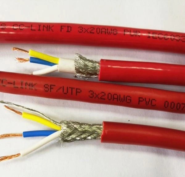
In the field of industrial automation, reliable data transmission and stable equipment connection are core guarantees for production efficiency. As a key supporting component of the CC-Link (Control & Communication Link) series—an important standard for industrial Ethernet and fieldbus technology—CC-Link industrial cable assemblies stand out for their strong anti-interference ability, high transmission stability, and wide environmental adaptability. They are widely applied in multiple industrial scenarios that demand strict communication performance, effectively bridging the information exchange between control systems, sensors, actuators, and other devices. 1. Smart Manufacturing Workshops Smart manufacturing relies on real-time data interaction between production line equipment to achieve automated scheduling and precision control, and CC-Link industrial cable assemblies are critical to this process. They connect programmable logic controllers (PLCs), human-machine interfaces (HMIs), and intelligent processing equipment (such as CNC machine tools and robotic arms) in workshops, ensuring real-time transmission of control signals and production data with a delay as low as milliseconds. In flexible production lines that require frequent equipment adjustments, the plug-and-play design of CC-Link cable assemblies reduces the time for equipment reconfiguration, while their resistance to mechanical wear adapts to the high-frequency movement of robotic arms and conveyor belts. 2. Automotive Manufacturing Industry The automotive manufacturing environment is characterized by high humidity, oil pollution, and strong electromagnetic interference (from welding equipment), which places strict demands on the durability and anti-interference performance of cable assemblies—requirements that CC-Link industrial cable assemblies fully meet. In welding workshops, they transmit data between welding robots, position sensors, and central control systems, with their flame-retardant and oil-resistant outer jackets preventing damage from splashed welding slag and machine oil. In final assembly lines, they connect vehicle detection equipment (such as laser alignment tools and pressure sensors) to the production management system, ensuring accurate collection of vehicle assembly data and supporting quality traceability. 3. Energy and Power Industry In energy sectors such as thermal power, wind power, and photovoltaic power generation, equipment operates in harsh environments (high temperature, high voltage, or outdoor exposure), and CC-Link industrial cable assemblies provide stable communication support for monitoring and control systems. In thermal power plants, they connect boiler pressure sensors, turbine speed detectors, and distributed control systems (DCS), enabling real-time monitoring of key parameters and ensuring safe operation of units. In wind farms, their weather-resistant (UV-proof, waterproof) and anti-corrosion properties adapt to outdoor environments, connecting wind turbine controllers to the central monitoring platform to transmit power generation data and fault signals. 4. Logistics and Material Handling Systems Automated logistics systems (such as automated warehouses, conveyor lines, and AGV robots) require seamless coordination between multiple devices, and CC-Link industrial cable assemblies ensure efficient data transmission in such scenarios. In automated warehouses, they connect stacker cranes, cargo position sensors, and warehouse management systems (WMS), enabling precise positioning of goods and automated inbound/outbound operations. For AGV robot fleets in factories, they support real-time communication between AGVs and the scheduling system, ensuring collision avoidance, path optimization, and smooth material transportation. 5. Food and Beverage Processing Industry The food and beverage industry has strict hygiene standards and requires frequent equipment cleaning, making CC-Link industrial cable assemblies with special material designs an ideal choice. Their food-grade, dust-proof, and washdown-resistant outer jackets (compliant with IP67/IP68 protection levels) can withstand high-pressure water washing and chemical cleaning agents, avoiding contamination risks. They connect filling machines, temperature controllers, and production line monitoring systems, ensuring accurate control of filling volumes and sterilization temperatures, and meeting food safety standards. In summary, CC-Link industrial cable assemblies are widely used in smart manufacturing, automotive, energy, logistics, and food industries due to their stability, environmental adaptability, and compatibility with CC-Link communication protocols. As industrial digitization accelerates, their role in ensuring reliable equipment communication and improving production efficiency will become even more prominent. If you need to expand the content for a specific industry (such as adding technical parameters of CC-Link cable assemblies in wind power scenarios), I can help you create a detailed industry-specific application sub-article to further enhance the article’s professionalism and targeted search traffic.

More

Voltage drop in industrial cables is a critical factor that directly impacts the performance, safety, and efficiency of electrical systems. Even small, unaccounted voltage drops can lead to equipment malfunctions, reduced motor lifespan, or increased energy consumption—making accurate calculation an essential skill for electrical engineers, technicians, and plant operators. This guide breaks down the calculation process step-by-step, using industry-standard formulas and real-world examples to ensure clarity and reliability. Why Voltage Drop Matters in Industrial Settings Before diving into calculations, understanding the importance of voltage drop helps prioritize accuracy. In industrial environments: Equipment Performance: Motors, sensors, and automated machinery require a stable voltage supply. A voltage drop exceeding 3% (the industry-recommended limit for most industrial circuits) can cause motors to run hotter, lose torque, or trip overload protectors. Safety Compliance: Standards like the IEC 60364 (International Electrotechnical Commission) and NEC 210 (National Electrical Code) mandate voltage drop limits to prevent fire hazards from overheated cables. Cost Efficiency: Undersized cables (a common cause of excessive voltage drop) force systems to draw more current, increasing energy bills and maintenance costs over time. Key Parameters Needed for Calculation To calculate voltage drop, you first need to gather 4 core parameters. These values are typically available in equipment manuals, cable datasheets, or electrical system designs: Load Current (I): The electrical current drawn by the connected equipment, measured in amps (A). For 3-phase systems, use the phase current (not line current) for accurate results. Cable Length (L): The one-way length of the cable from the power source to the load, measured in meters (m) or feet (ft). Do not use round-trip length unless specified by the formula. Cable Resistance (R): The electrical resistance of the cable per unit length, measured in ohms per meter (Ω/m) or ohms per 1000 feet (Ω/kft). This value depends on cable material (copper vs. aluminum) and cross-sectional area (e.g., 10 mm², 4 AWG). Power Factor (PF): For AC circuits only, the power factor represents the phase difference between voltage and current. Industrial loads (e.g., motors, transformers) typically have a PF between 0.7 (inductive, uncompensated) and 0.95 (compensated). Use 1.0 for DC circuits. Step-by-Step Calculation Methods The formula for voltage drop varies slightly between DC and AC circuits. Below are the industry-standard methods for both, along with simplified versions for quick estimates. 1. DC Circuit Voltage Drop DC circuits (e.g., battery-powered systems, DC motors) have no phase difference, so the calculation is straightforward. Formula: Voltage Drop (Vₙ) = 2 × I × L × R The “2” accounts for the current traveling to the load and returning to the source (round-trip resistance). Example: A 24V DC motor draws 15A. The cable is 50m long, with a resistance of 0.01 Ω/m.Vₙ = 2 × 15A × 50m × 0.01 Ω/m = 15VNote: A 15V drop in a 24V system is 62.5%—well above the safe limit. A larger cable (lower resistance) is required. 2. AC Circuit Voltage Drop AC circuits (the most common in industrial settings) require accounting for both resistance and reactance. For simplicity, most engineers use the simplified AC formula (valid for cables under 100m/300ft, where reactance is minimal). Simplified AC Formula (Single-Phase) Voltage Drop (Vₙ) = 2 × I × L × R × PF Example: A single-phase 230V pump draws 20A, with a PF of 0.8. The cable is 40m long, with a resistance of 0.008 Ω/m.Vₙ = 2 × 20A × 40m × 0.008 Ω/m × 0.8 = 10.24VVoltage Drop Percentage = (10.24V / 230V) × 100 = 4.45%Action: This exceeds the 3% limit—upgrade to a cable with lower resistance (e.g., 0.005 Ω/m). 3-Phase AC Formula (Balanced Loads) Most industrial systems (e.g., 3-phase motors, HVAC) use balanced 3-phase circuits. The formula accounts for the phase-to-phase voltage: Formula: Voltage Drop (Vₙ) = √3 × I × L × R × PF The “√3” (≈1.732) is the factor for 3-phase power distribution. Example: A 400V 3-phase motor draws 35A, with a PF of 0.9. The cable is 60m long, with a resistance of 0.006 Ω/m.Vₙ = 1.732 × 35A × 60m × 0.006 Ω/m × 0.9 ≈ 19.8VVoltage Drop Percentage = (19.8V / 400V) × 100 = 4.95%Action: Reduce length, increase cable size, or add power factor correction to lower the drop. Common Mistakes to Avoid Even with the right formula, errors in parameter selection can lead to incorrect results. Avoid these pitfalls: Using Round-Trip Length for DC/AC Formulas: Most standard formulas (including those above) already include a “2” (DC) or “√3” (3-phase) to account for return current. Double-counting length will inflate the voltage drop. Ignoring Temperature Effects: Cable resistance increases with temperature (e.g., copper resistance rises by ~0.4% per °C). For high-temperature environments (e.g., factories, outdoor cabinets), use the “corrected resistance” value from the cable datasheet. Overlooking Cable Material: Aluminum cables have 56% more resistance than copper cables of the same cross-sectional area. Always use the resistance value matching the cable material (copper is preferred for industrial applications due to lower resistance). Tools to Simplify Calculations For large-scale or complex systems, manual calculations can be time-consuming. Use these industry-trusted tools to streamline the process: Cable Datasheets: Manufacturers (e.g., Prysmian, Southwire) provide pre-calculated voltage drop values for their cables, sorted by current and length. Online Calculators: Tools like the NEC Voltage Drop Calculator or IEC 60364 Cable Calculator automate parameter input and formula application. Electrical Design Software: Programs like AutoCAD Electrical or ETAP integrate voltage drop calculations into full-system designs, ensuring compliance with global standards. Final Checks for Compliance After calculating the voltage drop, verify two critical factors to meet industrial standards: Voltage Drop Percentage: Ensure it stays below 3% for general industrial circuits and 5% for temporary installations (per NEC and IEC guidelines). Cable Ampacity: Confirm the cable’s ampacity (maximum safe current) exceeds the load current. A cable with sufficient ampacity reduces resistance and minimizes voltage drop over time. By following these steps, you can accurately calculate voltage drop in industrial cables, ensuring your electrical systems run safely, efficiently, and in compliance with global standards. Whether designing a new system or troubleshooting an existing one, this method provides a reliable framework for decision-making. If you need further customization, I can create a custom voltage drop calculation spreadsheet tailored to your specific industrial equipment (e.g., 3-phase motors, high-voltage cables) or regional standards (NEC, IEC, AS/NZS). Would you like me to prepare that?

More

In industrial environments—from factory automation and automotive manufacturing to heavy machinery and smart logistics—CAN (Controller Area Network) bus systems serve as the “nervous system” for real-time data transmission between sensors, controllers, and actuators. However, the performance of a CAN bus network hinges entirely on its industrial cable assemblies. Unlike standard cables, these assemblies are engineered to address the unique challenges of industrial settings, ensuring stable signal transmission, resistance to harsh conditions, and long-term durability. Below is a detailed breakdown of their critical attributes, selection criteria, and maintenance tips to maximize network efficiency. 1. Core Characteristics of High-Performance CAN Bus Cable Assemblies Industrial environments demand cable assemblies that go beyond basic signal transmission. The following features are non-negotiable for reliable CAN bus operation: Signal Integrity Optimization: CAN bus systems (e.g., CAN 2.0A/B, CAN FD) require precise impedance matching—typically 120Ω—to minimize signal reflection and attenuation. High-quality assemblies use twisted-pair conductors (24–22 AWG) to reduce crosstalk, while consistent conductor spacing and insulation materials (e.g., XLPE, PP) ensure stable impedance across temperature fluctuations (-40°C to 105°C or higher). Robust EMI/RFI Shielding: Industrial floors are filled with electromagnetic interference (EMI) from motors, inverters, and power tools, and radio-frequency interference (RFI) from wireless devices. Effective shielding is critical: most industrial CAN assemblies use a combination of aluminum foil (for full coverage) and tinned copper braid (for mechanical strength), with a drain wire for secure grounding. This design blocks external interference and prevents the cable itself from emitting noise that disrupts other systems. Mechanical & Environmental Durability: Cables in industrial settings face constant stress—vibration, abrasion, oil exposure, and chemical splashes. Premium assemblies use outer jackets made of PUR (Polyurethane) or TPU (Thermoplastic Polyurethane) for superior flexibility and resistance to oils, greases, and solvents. For harsh outdoor or washdown applications (e.g., food processing), jackets may also be rated IP67/IP68 for water and dust protection. 2. Key Selection Criteria for Industrial CAN Bus Cable Assemblies Choosing the right assembly requires aligning its specifications with your application’s unique needs. Avoid one-size-fits-all solutions by focusing on these factors: Match to Application Environment: For automotive or heavy machinery: Prioritize oil resistance (PUR jackets) and vibration tolerance. For food/pharmaceutical facilities: Select FDA-compliant, easy-to-clean jackets (e.g., smooth PVC or PUR) to meet hygiene standards. For extreme temperatures: Opt for high-temperature insulation (e.g., PTFE) for operations above 125°C, or low-temperature-rated materials for cold storage. Align with CAN Bus Protocol Requirements:CAN FD (Flexible Data Rate) systems, which support higher speeds (up to 8 Mbps) and larger data frames, require cables with tighter impedance control and lower capacitance than standard CAN 2.0. Ensure the assembly is labeled as “CAN FD-compatible” to avoid performance bottlenecks. Verify Connector Compatibility & Quality:The connector is often the weakest link in a cable assembly. Industrial CAN systems commonly use M12 connectors (male/female, 3-pin or 5-pin) for ruggedness, or DB9 connectors for legacy equipment. Look for connectors with gold-plated contacts (to resist corrosion) and IP-rated housings (IP65/IP67) for dust/water protection. Ensure the assembly’s connector pinout matches your device (e.g., CAN_H, CAN_L, GND). Check Industry Certifications:Compliance with global standards guarantees safety and interoperability. Look for assemblies certified to: UL/CSA: For North American electrical safety. CE: For European EMC (Electromagnetic Compatibility) and low-voltage directives. RoHS: To ensure no hazardous substances (e.g., lead, mercury) are used, critical for environmental compliance. 3. Installation & Maintenance Best Practices Even the highest-quality cable assembly will underperform without proper installation and care. Follow these guidelines to extend its lifespan and prevent network downtime: Avoid Excessive Bending or Tension: Respect the assembly’s minimum bend radius (typically 5–10x the cable diameter). Bending beyond this limit can damage the shield or conductors, leading to signal loss. Also, avoid pulling the cable by the connector—use the jacket for handling. Ensure Proper Shield Grounding: Only ground the shield on one end (e.g., at the controller) to prevent ground loops, which cause noise in the CAN bus. Use a dedicated ground terminal (not shared with power grounds) for optimal results. Conduct Regular Inspections: Schedule monthly checks for: Jacket damage (cracks, cuts, or oil swelling). Loose or corroded connectors. Shield continuity (use a multimeter to test resistance between the drain wire and connector shell).Replace assemblies at the first sign of wear to avoid unexpected system failures. Trust FRS for Your Industrial CAN Bus Cable Assembly Needs When reliability, performance, and durability matter, FRS’s industrial cable assembly factory delivers solutions tailored to your CAN bus requirements. With decades of expertise in industrial connectivity, FRS uses only premium materials—from twisted-pair conductors and EMI-resistant shielding to oil- and chemical-proof jackets—to ensure consistent signal transmission in the harshest environments. FRS offers full customization: whether you need CAN FD-compatible assemblies with M12 connectors for factory automation, FDA-approved options for food processing, or high-temperature designs for heavy machinery, our team works with you to meet exact specifications. Every assembly undergoes strict quality testing (including impedance verification and shielding effectiveness checks) and complies with UL, CE, and RoHS standards, ensuring seamless integration and long-term reliability. For industrial CAN bus cable assemblies that minimize downtime and maximize productivity, choose FRS—your partner in robust industrial connectivity.

More

Industrial cables are the lifeline of modern manufacturing, construction, and infrastructure projects—powering machinery, transmitting data, and ensuring operational safety. For businesses and procurement teams, finding wholesale sources that balance top-tier quality with competitive pricing is critical to controlling costs without compromising project reliability. The challenge lies not just in locating suppliers, but in identifying partners that meet strict industry standards and deliver consistent value. Below is a practical guide to reliable channels, key selection criteria, and how to avoid common pitfalls. Key Considerations Before Buying Wholesale Industrial Cable Before exploring channels, clarify your core requirements to narrow down options and avoid costly mistakes. These factors directly impact the suitability of a supplier: Quality Certifications: Prioritize cables certified by global standards like UL (U.S.), CE (EU), ISO 9001, or GB (China). These certifications verify compliance with safety, durability, and performance benchmarks—essential for industrial environments where cable failure can cause downtime or hazards. Customization Capabilities: Industrial projects often require cables with specific lengths, insulation materials (e.g., PVC, Teflon), or voltage ratings. Choose suppliers that offer tailored solutions to avoid wasting money on off-the-shelf products that don’t fit. Inventory & Lead Times: Wholesale buyers typically need bulk orders quickly. Confirm the supplier has sufficient stock or can deliver within your project timeline—delays in cable supply can hold up entire operations. After-Sales Support: Look for suppliers that provide technical assistance (e.g., installation guidance) and warranty coverage. If a batch of cables has defects, reliable after-sales service ensures you can resolve issues without extra costs. Reliable Channels to Buy High-Quality Industrial Cable Wholesale 1. Specialized Industrial Cable Wholesalers These suppliers focus exclusively on industrial cables, making them experts in the field. They often partner with multiple manufacturers, offering a wide range of products (e.g., power cables, control cables, data cables) to suit different industries (automotive, energy, construction). Advantages: Broad product selection, in-depth technical knowledge, and flexible order quantities (from small bulk to large-scale shipments). Many also provide value-added services like cable cutting or labeling. How to Choose: Check their track record—look for customer reviews, case studies, or references from businesses in your industry. Verify that their products carry the necessary certifications and ask for sample tests before placing large orders. 2. Direct Purchasing from Manufacturing Factories Buying directly from factories eliminates middlemen, which often translates to lower wholesale prices and more control over product quality. Factories are also better equipped to handle custom orders, as they can adjust production processes to meet your exact specifications. Advantages: Lower costs, direct communication with production teams (for customization), and transparency in quality control. You can also visit the factory (in-person or virtually) to inspect manufacturing processes. How to Choose: Ensure the factory has a proven production capacity (e.g., annual output, advanced equipment) and meets international quality standards. Confirm their minimum order quantity (MOQ)—some factories require larger batches, so align this with your needs. 3. B2B E-Commerce Platforms Reputable B2B platforms connect buyers with verified industrial cable suppliers (wholesalers or factories) worldwide. These platforms simplify comparison shopping, allowing you to evaluate prices, certifications, and supplier ratings in one place. Popular Options: Alibaba, Thomasnet, or IndustryNet. Many platforms offer trade assurance services, which protect your payment until you confirm the order meets your requirements. How to Choose: Prioritize suppliers with “verified” badges (indicating the platform has checked their business credentials). Request product samples and clarify shipping costs (critical for international orders) before finalizing a deal. Avoid suppliers with vague product descriptions or no certification documentation. How to Avoid Wholesale Purchasing Risks Even with reliable channels, risks like receiving substandard cables or delayed shipments exist. Mitigate these by: Testing Samples: Always request 1-2 sample cables to test for durability, conductivity, and compliance with your project’s requirements. Verifying Certifications: Ask suppliers to provide original certification documents (not just photos) and cross-check them with official databases (e.g., UL’s Online Certifications Directory). Signing Detailed Contracts: Include clauses for quality standards, delivery timelines, payment terms, and defect resolution. This ensures both parties are accountable. Why Choose FRS Factory for Wholesale Industrial Cable When it comes to sourcing high-quality industrial cable at wholesale prices, FRS Factory stands out as a trusted direct manufacturer. With over a decade of experience serving global clients in energy, manufacturing, and construction, FRS delivers on both quality and value. All FRS industrial cables are certified by UL, CE, and ISO 9001, ensuring they withstand harsh industrial conditions—from high temperatures to chemical exposure. We offer flexible customization (length, insulation, voltage) with no excessive MOQs, making us ideal for both small-batch and large-scale wholesale orders. Our in-house inventory ensures fast delivery (typically 7-15 days for standard products), and our technical team provides 24/7 after-sales support to resolve any issues. For businesses looking to cut costs without sacrificing reliability, FRS Factory is your one-stop solution for wholesale industrial cable. Contact us today to get a tailored quote and sample test.

More

High-humidity warehouses—such as those for food processing, pharmaceutical storage, or coastal logistics—pose unique risks to industrial cables, including insulation degradation, conductor corrosion, and short circuits. Selecting the right cable is not just about ensuring operational continuity; it also prevents costly downtime and safety hazards. Below is a practical, step-by-step guide to help you make an informed choice, along with key factors to prioritize and pitfalls to avoid. 1. Key Performance Factors to Prioritize Not all industrial cables are designed for moisture resistance. Focus on these four non-negotiable attributes to ensure durability in high-humidity environments: Insulation Material: Opt for materials with strong moisture barrier properties. Cross-linked polyethylene (XLPE) and ethylene propylene diene monomer (EPDM) are top choices—XLPE resists water absorption and maintains electrical insulation even when exposed to condensation, while EPDM offers excellent resistance to humidity, aging, and mild chemicals (common in food or pharmaceutical warehouses). Avoid standard PVC insulation, as it can become brittle and leak current over time in persistent moisture. Protective Sheathing: The outer sheath acts as the first line of defense against moisture and physical damage. Choose waterproof sheaths made of chlorinated polyethylene (CPE) or thermoplastic polyurethane (TPU); these materials repel water, resist mold growth, and withstand abrasion from warehouse equipment (e.g., forklifts). For extra protection in damp, dusty areas, select sheaths with anti-microbial additives to prevent fungus buildup. Conductor Material & Coating: Bare copper conductors are prone to corrosion in high humidity. Instead, use tinned copper conductors—the tin coating creates a barrier against moisture and oxidation, extending the cable’s lifespan. For heavy-duty applications (e.g., powering large refrigeration units), consider stranded conductors over solid ones; they are more flexible and less likely to crack under temperature fluctuations (a common issue in humid spaces with cooling systems). Industry Certifications: Verify that the cable meets global standards for moisture resistance. Look for certifications like UL 1581 (for electrical performance in wet conditions), IEC 60502 (for power cables in harsh environments), or NFPA 70 (National Electrical Code) compliance for fire safety—critical in warehouses where moisture can increase fire risks from electrical faults. 2. A Practical 4-Step Selection Process To avoid overcomplicating the choice, follow this straightforward process tailored to high-humidity warehouses: Assess Your Environment First: Document key conditions to narrow down options. Note the average humidity level (e.g., 75%+ for tropical warehouses vs. 60-70% for refrigerated spaces), temperature range (e.g., 0°C to 30°C), and presence of contaminants (e.g., water splashes, chemical vapors, or dust). For example, a seafood warehouse with frequent water exposure will need a cable with a more robust waterproof sheath than a dry-goods warehouse with just high ambient humidity. Define the Cable’s Purpose: Clarify if the cable is for power transmission (e.g., connecting motors), control signals (e.g., monitoring inventory systems), or data transfer (e.g., IoT sensors). Power cables need thicker insulation and higher current ratings, while control/data cables require shielded designs to prevent moisture from disrupting signals. Cross-Check with Installation Requirements: Consider how and where the cable will be installed. If it will be buried in damp concrete or run along wet floors, choose a cable with armor protection (e.g., steel tape or wire armor) to resist physical damage and water seepage. For overhead installation, select a lightweight, UV-resistant sheath (if exposed to natural light) to avoid degradation. Evaluate Long-Term Maintenance: Opt for cables that are easy to inspect and maintain. For example, cables with transparent or color-coded sheaths let you spot early signs of moisture damage (e.g., discoloration or swelling) without stripping the insulation. Avoid cables with complex, hard-to-repair designs—this reduces maintenance time and costs over the cable’s lifecycle. 3. Common Pitfalls to Avoid Even with careful planning, many buyers make mistakes that compromise cable performance: Ignoring temperature-humidity interaction: High humidity combined with extreme temperatures (e.g., cold refrigerators or hot machinery) can 加速 insulation breakdown. Always choose cables rated for the full temperature range of your warehouse, not just humidity. Prioritizing cost over quality: Cheap, non-moisture-resistant cables may save money upfront, but they often fail within 1-2 years in high-humidity settings—leading to expensive replacements and downtime. Investing in a quality cable can extend lifespan to 5-10 years. Overlooking shielding for control/data cables: Moisture can interfere with electrical signals, causing errors in inventory tracking or equipment control. Always use shielded cables (e.g., foil or braided shielding) for control and data applications in damp environments. Conclusion Choosing industrial cables for high-humidity warehouses requires balancing moisture resistance, durability, and application needs. By focusing on insulation, sheathing, conductor quality, and certifications—and following a structured selection process—you can minimize risks and ensure long-term reliability. For businesses seeking cables tailored to high-humidity challenges, FRS brand factory delivers solutions engineered for these exact conditions. FRS industrial cables use premium XLPE/EPDM insulation, tinned copper conductors, and waterproof CPE/TPU sheaths, all certified to UL 1581 and IEC 60502 standards. Whether you need power cables for refrigerated warehouses or shielded control cables for coastal facilities, FRS offers customized designs to match your environment and application—backed by technical support to help you select the right product and avoid costly mistakes. Trust FRS to keep your high-humidity warehouse operations running smoothly, safely, and efficiently.

More

Industrial cables are critical components in sectors like oil & gas, power transmission, and railways, where fire incidents can trigger catastrophic losses. Fire resistance testing ensures these cables maintain electrical continuity and prevent flame spread during a fire, safeguarding both equipment and human life. Below is a step-by-step breakdown of the standardized testing process, aligned with global norms such as IEC (International Electrotechnical Commission) and UL (Underwriters Laboratories). 1. Pre-Test Preparation: Lay the Groundwork for Accuracy Before testing begins, meticulous preparation is essential to ensure results are reliable and comparable. Sample Selection: Choose representative cable samples that match the actual product specifications (e.g., conductor size, insulation material, sheath type). Most standards require 3–5 samples, each 1.5–3 meters long, to account for manufacturing variability. Environment Calibration: Adjust the test chamber to controlled conditions—typically 23±5°C temperature and 45–75% relative humidity. This eliminates environmental factors that could skew results, such as moisture affecting insulation flammability. Standard Confirmation: Define the applicable standard based on the cable’s end-use. For example, IEC 60332-3-24 applies to vertical flame testing of power cables, while UL 1685 focuses on fire performance of communication cables in vertical shafts. 2. Core Testing Procedures: Evaluate Fire Resistance Performance This phase focuses on two key metrics: flame spread prevention and electrical continuity maintenance—the two pillars of fire-resistant cable performance. 2.1 Vertical Flame Test (Most Common for Industrial Cables) This test simulates a fire originating below the cable (e.g., from a nearby equipment fire) and assesses if flames spread upward. Mount the cable sample vertically in a test chamber, with a propane burner (producing a 125mm blue flame at 815±10°C) positioned 50mm below the sample’s lower end. Apply the flame continuously for 90 minutes (per IEC standards) or 60 minutes (per UL standards). Monitor two criteria: Flame spread: The flame front must not reach 1.5 meters above the burner. Electrical continuity: The cable must maintain power transmission (tested via a 110V circuit with a light indicator) throughout the test—interruption means failure. 2.2 Smoke Density and Toxic Gas Testing Modern standards go beyond flame resistance to address post-fire safety, as thick smoke and toxic fumes hinder evacuation and damage equipment. Smoke Density: Use a NBS (National Bureau of Standards) smoke chamber to measure light transmittance through smoke generated by the burning cable. A transmittance value above 60% (after 4 minutes of burning) is typically required to pass. Toxic Gas Emission: Analyze gas samples (via gas chromatography) for harmful compounds like carbon monoxide (CO), hydrogen chloride (HCl), and sulfur dioxide (SO₂). Limits vary by standard—for example, IEC 61034 caps HCl emission at 5mg/g of cable material. 2.3 Horizontal Flame Test (for Specific Applications) Used for cables installed in horizontal runs (e.g., under floors), this test places the sample horizontally on a fire-resistant support. A burner is applied to the sample’s midpoint for 30 minutes, with the pass criteria being no flame spread beyond 500mm from the burner and no dripping of flaming material that ignites a cotton pad below. 3. Data Recording & Analysis: Validate Compliance During testing, record real-time data to quantify performance and verify compliance: Key parameters: Flame application time, flame spread distance, electrical continuity status, smoke density values, and toxic gas concentrations. Compliance check: Compare results against the pre-defined standard. For example, if a cable’s smoke density drops to 45% (below the 60% threshold), it fails the smoke density requirement. Repeat testing: If initial results are inconsistent, retest with new samples to rule out human error or sample defects. 4. Test Report Compilation: Document Results for Stakeholders A comprehensive report is the final output, serving as proof of compliance for customers, regulators, and certification bodies. It must include: Cable details: Model number, material composition, and dimensions. Test conditions: Standard used, chamber temperature/humidity, and burner specifications. Results: Quantitative data (e.g., “Flame spread limited to 800mm”) and a clear pass/fail conclusion. Sign-off: Certification from an accredited testing body (e.g., ISO 17025) to validate the test’s credibility. Why This Process Matters Fire resistance testing is not just a regulatory requirement—it is a critical step in mitigating fire risks in industrial settings. A cable that passes these tests ensures emergency systems (e.g., fire alarms, exit lights) remain functional during a fire, buying time for evacuation and minimizing property damage. At FRS, we treat fire resistance testing as a non-negotiable part of our industrial cable production. Our in-house labs are equipped with ISO 17025-accredited equipment, capable of conducting all core tests (vertical flame, smoke density, toxic gas) to IEC, UL, and GB standards. Our team of engineers oversees every step—from sample selection to report validation—to ensure each FRS cable delivers consistent, reliable fire performance. Whether you need cables for oil rigs, high-speed railways, or data centers, FRS has the tested solution to keep your operations safe.

More

Industrial cables serve as the “nerve system” for critical infrastructure—power transmission, manufacturing lines, renewable energy farms, and outdoor industrial zones all rely on their stable performance. However, when deployed in outdoor or semi-outdoor environments (such as rooftop solar installations, overhead power lines, or open-air factories), these cables face a persistent and destructive threat: ultraviolet (UV) radiation from sunlight. Unlike residential cables, industrial-grade cables carry higher voltages, endure heavier mechanical loads, and must operate continuously for years or even decades. Without adequate UV protection, their lifespan and safety are severely compromised—making UV resistance a non-negotiable requirement for industrial cable design. 1. UV radiation damages core cable materials The outer insulation and sheathing of industrial cables are typically made of polymers like PVC, polyethylene (PE), or cross-linked polyethylene (XLPE). UV rays break down the chemical bonds in these polymers through a process called photo-oxidation, leading to irreversible material degradation: Insulation hardening and cracking: Over time, UV exposure makes the insulation layer brittle. Small cracks form on the surface, then spread inward—exposing the metal conductors inside to moisture, dust, and corrosive substances. Loss of flexibility: Industrial cables often need to withstand bending or vibration (e.g., cables in conveyor belts or construction machinery). UV-damaged sheathing loses its elasticity, making it prone to tearing during routine maintenance or operational movement. Color fading and material erosion: The outer sheath may fade from black to gray, a visible sign of polymer breakdown. In extreme cases, the sheath can flake off, leaving the cable’s internal structure unprotected. 2. UV damage risks electrical safety and operational failure Industrial systems demand zero tolerance for cable malfunctions, as even a single faulty cable can cause production halts, equipment damage, or safety hazards. UV-induced degradation directly undermines electrical performance: Reduced insulation resistance: Cracks in the insulation layer allow moisture to seep in, lowering the cable’s ability to resist electrical leakage. This increases the risk of short circuits, ground faults, or even electrical fires—especially in high-voltage industrial applications. Signal interference (for data cables): Many industrial cables (e.g., those used in automation or IoT systems) transmit critical data. UV damage can disrupt the cable’s shielding, leading to signal loss or interference that compromises process control and monitoring. Premature cable failure: Unprotected industrial cables exposed to UV may fail in 2–5 years, far shorter than their intended 10–20-year lifespan. Replacing cables in hard-to-reach areas (e.g., tall utility poles or underground industrial trenches) adds significant maintenance costs and downtime. 3. UV interacts with other environmental factors to amplify harm Industrial environments rarely expose cables to UV alone—UV radiation often acts in tandem with other stressors, accelerating damage: High temperatures: Outdoor industrial areas (e.g., steel mills, desert solar farms) experience extreme heat. UV radiation absorbs into the cable sheath, raising its internal temperature and speeding up polymer oxidation. Moisture and chemicals: Rain, humidity, or industrial pollutants (e.g., oils, solvents) seep through UV-induced cracks, causing corrosion of the metal conductors and further weakening the insulation. Ozone exposure: Industrial processes (e.g., welding, chemical manufacturing) generate ozone, which reacts with UV-damaged polymers to break down their molecular structure even faster. Key UV protection measures for industrial cables To mitigate these risks, manufacturers integrate targeted UV protection into industrial cable design: Use UV-resistant base materials: Premium polymers like ethylene propylene diene monomer (EPDM), chlorosulfonated polyethylene (CSPE), or fluoropolymers (e.g., PTFE) are inherently resistant to UV degradation, replacing standard PVC in outdoor applications. Add UV stabilizers and antioxidants: During production, additives like hindered amine light stabilizers (HALS) or benzophenone derivatives are mixed into the polymer. These compounds absorb or scatter UV rays, preventing photo-oxidation. Implement robust outer sheathing: Thick, weather-resistant sheaths (often black, as dark colors absorb less UV than light ones) or dual-layer designs (a UV-resistant outer layer plus an inner insulation layer) provide extra protection. Apply protective coatings: For specialized applications (e.g., marine industrial cables), a thin layer of UV-blocking resin is applied to the sheath to enhance resistance to saltwater and UV. Trust FRS for industrial cables with reliable UV protection When industrial operations depend on cables that withstand harsh outdoor conditions, FRS brand factory delivers solutions engineered for durability. We prioritize UV resistance at every stage of production: using high-grade UV-resistant polymers (EPDM, CSPE), integrating industrial-grade HALS stabilizers, and subjecting each cable to 1,000+ hours of accelerated UV testing (simulating 10 years of outdoor exposure) to ensure no degradation. Whether for solar power plants, outdoor manufacturing lines, or overhead power transmission, FRS industrial cables maintain electrical stability, mechanical flexibility, and long lifespan—even under intense UV and environmental stress. Choose FRS, and let your industrial systems run safely, continuously, and cost-effectively.

More

In modern industrial settings—from automated assembly lines to robotic arms and conveyor systems—cables are not just passive transmitters of power or signals. They operate in constant motion, bending, twisting, and flexing hundreds or thousands of times daily. Standard industrial cables often fail quickly under such stress, leading to unplanned downtime, costly repairs, and compromised productivity. High-flex industrial cables, however, are engineered to thrive in dynamic environments, delivering a range of practical benefits that directly address the pain points of industrial operations. 1. Exceptional Durability & Longer Service Life The core advantage of high-flex industrial cables lies in their resistance to flex fatigue. Unlike standard cables, which use rigid conductors and thin insulation that crack or break after repeated bending, high-flex cables are built with specialized materials: Stranded conductors: Fine, multiple strands of copper (instead of single solid wires) allow the cable to bend without stretching or snapping, even under high-frequency motion. Reinforced insulation: Materials like TPE (thermoplastic elastomer) or PUR (polyurethane) provide flexibility while resisting abrasion, tearing, and wear from constant movement.This design drastically extends service life—high-flex cables can withstand 10 million or more flex cycles, compared to just 100,000 cycles for standard cables. For factories running 24/7, this means fewer cable replacements and less disruption to production. 2. Uninterrupted Signal & Power Integrity In precision-driven industries (e.g., electronics manufacturing, automotive assembly), even minor signal loss or power fluctuations can ruin products or trigger equipment malfunctions. High-flex cables maintain consistent performance under motion: Their stranded conductors and low-capacitance insulation minimize signal distortion, ensuring reliable data transmission for sensors, encoders, and control systems. For power cables, the flexible design prevents voltage drops caused by conductor damage, keeping motors and machinery running at optimal efficiency. 3. Adaptability to Harsh Industrial Environments Industrial sites are rarely gentle—cables face exposure to oils, coolants, chemicals, extreme temperatures (-40°C to 125°C), and even mechanical impact. High-flex cables are engineered to withstand these conditions: Chemical resistance: PUR or TPE insulation repels oils, solvents, and cleaning agents that degrade standard PVC cables. Temperature stability: They remain flexible in freezing cold or high-heat areas (e.g., near furnaces or refrigeration units), avoiding brittleness or melting. Moisture protection: Many high-flex cables include water-resistant jackets, making them suitable for washdown areas (e.g., food processing plants) or outdoor installations. 4. Reduced Maintenance Costs & Downtime Unplanned downtime is one of the biggest costs for manufacturers—each hour of halted production can cost thousands of dollars. High-flex cables cut this risk by: Minimizing cable failures: Their durability means fewer unexpected breakdowns that force lines to stop. Simplifying replacements: When replacements are needed, high-flex cables are often lighter and more flexible, making them easier to install in tight spaces (e.g., inside robotic arms) and reducing maintenance time.Over time, these savings far outweigh the initial higher cost of high-flex cables compared to standard options. 5. Enhanced Operational Safety Safety is non-negotiable in industrial settings, and cable failures can pose serious risks (e.g., short circuits, electrical fires, or equipment collisions). High-flex cables improve safety by: Maintaining insulation integrity: Even after repeated flexing, their insulation rarely cracks, preventing exposed conductors that cause shocks or fires. Meeting industry standards: Most high-flex cables comply with global safety certifications (e.g., UL, CE, IEC), ensuring they meet strict requirements for flame resistance and electrical safety. When it comes to choosing high-flex industrial cables that deliver these benefits consistently, FRS brand factory stands out as a trusted partner for manufacturers worldwide. With over a decade of experience in engineering industrial cables, FRS focuses on precision: every high-flex cable is made with high-grade stranded copper conductors and industrial-grade insulation, undergo 100% flex cycle testing, and are tailored to meet specific industry needs—whether for robotics, automation, or harsh-environment applications. FRS doesn’t just supply cables; it provides reliable solutions that reduce downtime, lower maintenance costs, and keep your operations running smoothly. For industrial cables that combine durability, performance, and safety, FRS is the choice that powers productivity.

More

The entertainment industry is a symphony of technology and creativity, where every dazzling light, crisp sound, and seamless mechanical movement relies on an unsung hero: industrial cable. Unlike standard cables designed for residential or office use, industrial cables are engineered to withstand the entertainment sector’s unique challenges—frequent movement, extreme temperatures, electromagnetic interference (EMI), and constant setup/teardown. From film sets to concert stages, theme parks to esports arenas, these cables form the invisible backbone that turns creative concepts into immersive experiences. Below is a detailed breakdown of how industrial cables power and enable key segments of the entertainment industry. 1. Industrial Cables in Film and Television Production Film and TV production demands precision, reliability, and adaptability—whether shooting on a soundstage, a remote mountain location, or a bustling city street. Industrial cables address these needs by ensuring uninterrupted power and signal flow for critical equipment, preventing costly delays and preserving creative vision. 1.1 Powering Camera and Audio Equipment Professional film cameras, high-definition (HD) monitors, and audio recorders require stable power to capture crisp visuals and clear sound. Industrial power cables, built with reinforced conductors and abrasion-resistant insulation, are ideal for this task. Unlike residential cables that fray under repeated handling, industrial variants withstand the rigors of on-set use—crew members can drag them across concrete, dirt, or water without damaging the core. For example, a documentary crew filming in a rainforest might use waterproof industrial power cables to keep cameras running during downpours, while a studio shoot could rely on flexible industrial cables to power cameras mounted on moving gimbals or cranes. 1.2 Supporting Complex Lighting Rigs Lighting is the backbone of visual storytelling in film and TV, and industrial cables are essential for powering and controlling complex lighting setups. High-wattage spotlights, LED panels, and DMX controllers (used to sync lighting effects) require cables that handle high current loads without overheating. Heat-resistant industrial cables—rated to withstand temperatures up to 180°C—are used here, ensuring lights stay operational even when placed near hot fixtures. Additionally, shielded industrial cables connect DMX controllers to lighting units, blocking EMI from nearby power sources. This prevents flickering or signal loss, ensuring the lighting matches the director’s exact vision—whether it’s a warm sunset scene or a dramatic action sequence. 1.3 Enabling Seamless Post-Production Post-production facilities—where editors, colorists, and sound designers refine footage—depend on industrial cables for fast, error-free data and power transmission. Editing suites house servers, workstations, and storage devices that transfer large 4K/8K video files in real time. Industrial Ethernet cables (with high bandwidth and low latency) connect these devices, eliminating buffering and ensuring files are not corrupted during transfer. Power distribution units (PDUs) in these facilities also use industrial power cables, which provide stable voltage to sensitive equipment. This protects against power surges that could erase hours of work, keeping post-production timelines on track. 2. Industrial Cables in Live Entertainment: Concerts and Theater Live entertainment—from sold-out arena concerts to intimate theater productions—relies on industrial cables to deliver dynamic, glitch-free experiences. These cables must handle constant movement (e.g., moving stages, hanging speakers) and perform flawlessly in high-pressure environments where even a single second of downtime can ruin a show. 2.1 Controlling Stage Machinery Modern concerts and theater productions feature elaborate stage setups: moving platforms, elevating curtains, pyrotechnic systems, and rotating props. All these rely on industrial control cables—equipped with multiple conductors—to connect machinery to its control system. These cables are flexible enough to bend with moving parts (e.g., a rising stage platform) and durable enough to withstand hundreds of setup/teardown cycles. For example, a pop star’s world tour might use industrial control cables to power a hydraulic stage that lifts the artist above the audience. The cables’ resistance to wear ensures the stage moves smoothly night after night, regardless of venue conditions. 2.2 Delivering Crystal-Clear Audio Sound quality is make-or-break for live events, and industrial cables are key to transmitting clean audio. Concert sound systems use industrial-grade audio cables (e.g., shielded XLR cables) to connect microphones, instruments, and mixers to speakers. The shielding in these cables blocks interference from nearby power cables or radio signals, preventing static, hum, or dropouts. For large festivals with multiple stages, long-length industrial audio cables maintain signal integrity over distances of 100+ meters, ensuring every audience member—whether in the front row or the back—hears the music as intended. Theaters also use these cables for their sound systems, ensuring dialogue and music are clear even in acoustically challenging spaces. 2.3 Syncing Lighting and Visual Effects Live shows often combine lighting with visual effects like projection mapping or laser displays—requiring synchronized power and signal transmission. Industrial composite cables (which carry both power and data) simplify installations by reducing cable clutter. For example, a Broadway musical might use projection mapping to turn a static set into a rotating forest. Industrial composite cables supply power to the projectors while transmitting HD video signals, ensuring the visuals align perfectly with the music and acting. Laser systems—sensitive to EMI—also use shielded industrial cables to prevent glitches, keeping the show’s timing precise. 3. Industrial Cables in Theme Parks and Amusement Venues Theme parks are designed to immerse guests in magical worlds, and industrial cables are critical to powering rides, 特效 (special effects), and infrastructure. These cables must withstand harsh outdoor conditions (rain, UV radiation, extreme temperatures) and ensure safety—non-negotiable for rides that carry thousands of guests daily. 3.1 Ensuring Safe Ride Operation Roller coasters, spinning rides, and dark rides depend on industrial cables for power and safety. Heavy-duty industrial power cables supply electricity to ride motors, brakes, and safety sensors, with designs that resist vibration and wear. For example, a roller coaster’s lift hill motor requires a cable that handles high torque loads and remains intact even when exposed to rain or snow. Industrial control cables also connect ride sensors to central monitoring systems, sending real-time data (speed, pressure, position) to operators. This ensures rides stay within safe parameters, preventing accidents and keeping guests secure. 3.2 Powering Immersive Effects Modern theme parks use 特效 like water sprays, fire effects, and animatronics to create engaging experiences—and industrial cables make these possible. Waterproof industrial cables are used in water rides (e.g., log flumes) to power underwater lighting, sprayers, and audio systems. These cables are sealed to prevent water damage, even when submerged. Animatronic attractions—like a pirate ship with moving figures—use industrial control cables to sync movements (e.g., a pirate’s wave) with sound effects. The cables’ flexibility allows animatronics to move naturally, while their durability ensures the attraction runs reliably for years. 3.3 Supporting Park Infrastructure Beyond rides, theme park infrastructure—lighting, security, and food service—relies on industrial cables. Outdoor parking lots and walkways use weather-resistant industrial cables for lighting, which withstand UV radiation and extreme temperatures without deteriorating. Security cameras (spread across the park) use industrial Ethernet cables to transmit HD video to a central monitoring station, helping staff monitor safety. Even food stalls depend on industrial power cables to run refrigerators, grills, and cash registers—these cables handle the high power demands of commercial kitchen equipment, ensuring stalls stay operational during peak hours. 4. Industrial Cables in Esports and Live Streaming The esports and live streaming industries have exploded in popularity, with tournaments drawing millions of viewers online and in-person. These sectors require cables that deliver ultra-low latency and 24/7 reliability—any lag or downtime can cost teams victories or streamers viewers. 4.1 Powering Gaming Setups Esports tournaments (e.g., Dota 2’s The International) feature professional gamers using high-performance PCs, monitors, and peripherals. These setups need industrial power cables to ensure consistent voltage—fluctuations can cause PCs to crash, ruining a player’s performance. Industrial USB and HDMI cables connect keyboards, mice, and monitors, with low-latency designs that register every input instantly (critical for fast-paced games like Valorant). For in-person events, cables are also designed to be easy to route under tables and around equipment, keeping gaming areas organized and safe. 4.2 Enabling High-Quality Live Streaming Live streaming of esports, concerts, or award shows requires cables that transmit large amounts of data without buffering. Streaming setups (cameras, microphones, encoders, servers) use industrial Ethernet cables to send video and audio to platforms like Twitch or YouTube. These cables handle high bandwidth, ensuring 1080p/4K streams reach viewers without quality loss. Backup industrial pow.

More

In industrial settings—from manufacturing plants and power distribution networks to renewable energy facilities and heavy machinery operations—industrial cables are the lifelines of electrical systems. They transmit power and signals that keep critical equipment running, and their performance directly impacts operational efficiency, safety, and downtime. One of the most critical specifications of an industrial cable is its current carrying capacity (often called ampacity), which refers to the maximum electric current a cable can safely conduct without overheating or degrading. While factors like conductor material (copper vs. aluminum), insulation type, and environmental conditions (temperature, humidity, and installation method) influence ampacity, industrial cable thickness stands out as a foundational factor. This article breaks down why thickness matters, how it interacts with electrical principles to shape performance, and why choosing the right thickness is non-negotiable for industrial applications. 1. The Basics: What Is Current Carrying Capacity, and Why Does It Matter? Before diving into thickness, it’s essential to clarify what current carrying capacity means for industrial operations. Ampacity is not an arbitrary number; it’s defined by international standards (such as IEC 60287, NEC 310 in the U.S., and BS 7671 in the UK) to ensure cables operate within safe thermal limits. When a cable carries current, it generates heat—a byproduct of electrical resistance. If the current exceeds the cable’s ampacity, the heat buildup becomes excessive, leading to: Degradation of insulation materials, which can crack, melt, or lose dielectric strength (increasing the risk of short circuits or electric shocks). Premature cable failure, which causes unplanned downtime—costly for industries where even minutes of stoppage can result in thousands of dollars in losses. Fire hazards, as overheated cables can ignite nearby flammable materials (a major safety risk in oil refineries, chemical plants, or warehouses). For industrial users—whether they’re specifying cables for a new assembly line, upgrading a power grid, or replacing worn wiring—understanding how thickness affects ampacity is key to avoiding these risks and ensuring long-term system reliability. 2. The Science: Cable Thickness, Resistance, and Heat Generation The link between industrial cable thickness and current carrying capacity starts with a fundamental law of physics: Ohm’s Law, which describes the relationship between current (I), voltage (V), and resistance (R) (V = IR). For cables, resistance is not fixed—it depends heavily on the conductor’s cross-sectional area (i.e., thickness). 2.1 Cross-Sectional Area and Electrical Resistance Industrial cable thickness is typically measured by the cross-sectional area of its conductor, expressed in square millimeters (mm²) or American Wire Gauge (AWG). The AWG system is inverse: smaller AWG numbers mean thicker cables (e.g., 4 AWG is thicker than 12 AWG). The resistance of a conductor is calculated using the formula: R = ρL/A Where: R = Resistance (ohms, Ω) ρ = Resistivity (a material-specific constant; copper has lower resistivity than aluminum, making it a better conductor) L = Length of the conductor (meters, m) A = Cross-sectional area (mm² or m²) This formula makes it clear: resistance is inversely proportional to cross-sectional area. In other words, a thicker cable (larger A) has lower resistance (R) than a thinner cable of the same material and length. Why does lower resistance matter for ampacity? Because heat generation in a cable follows Joule’s Law, which states that the heat (Q) produced is: Q = I²Rt Where t = time (seconds, s). For a given current (I) and time (t), a cable with lower resistance (R) generates less heat. This means thicker cables can handle higher currents without exceeding safe temperature limits—directly increasing their current carrying capacity. 2.2 Example: Thickness vs. Resistance in Industrial Cables To put this into perspective, consider two copper industrial cables of the same length (10 meters) but different thicknesses: A 2.5 mm² cable (14 AWG) has a resistance of approximately 0.68 Ω/10m. A 10 mm² cable (8 AWG) has a resistance of approximately 0.17 Ω/10m. At a current of 20 amps (A), the 2.5 mm² cable generates Q = (20)² × 0.68 × 60 = 16,320 joules (J) of heat per minute. The 10 mm² cable, by contrast, generates Q = (20)² × 0.17 × 60 = 4,080 J per minute—four times less heat. This means the 10 mm² cable could safely carry a much higher current (e.g., 40 A) while still generating less heat than the 2.5 mm² cable at 20 A. 3. Heat Dissipation: Thicker Cables Manage Thermal Load More Effectively Beyond reducing heat generation, industrial cable thickness also improves heat dissipation—the ability to transfer excess heat away from the conductor and into the surrounding environment. This is critical for industrial applications where cables are often installed in harsh conditions (e.g., tight enclosures, underground trenches, or high-temperature areas like foundries). 3.1 Surface Area and Heat Transfer Thicker cables have a larger outer surface area relative to their conductor volume (a key metric for heat dissipation). Heat naturally flows from hotter areas (the conductor) to cooler areas (the environment), and a larger surface area provides more “space” for this heat to escape. For example: A 4 mm² (12 AWG) copper cable has an outer diameter of ~5 mm and a surface area of ~15.7 mm² per meter. A 25 mm² (4 AWG) copper cable has an outer diameter of ~10 mm and a surface area of ~31.4 mm² per meter—double the surface area of the 4 mm² cable. This larger surface area allows the thicker cable to dissipate heat faster, even if it’s carrying a higher current. In enclosed spaces (e.g., control panels with limited airflow), this difference is even more pronounced: a thin cable may overheat quickly, while a thick cable maintains safe temperatures. 3.2 Thermal Mass: Thicker Cables Resist Temperature Spikes Thicker cables also have greater thermal mass—the amount of heat required to raise their temperature by a given amount. This means they can absorb temporary current surges (common in industrial machinery like motors or pumps) without experiencing sudden, dangerous temperature spikes. For example, when a motor starts, it draws a “inrush current” that can be 5–10 times its normal operating current. A thin cable may overheat during this surge, but a thick cable’s thermal mass acts as a buffer, keeping temperatures within safe limits until the current stabilizes. 4. Industrial Applications: The Cost of Ignoring Cable Thickness In industrial settings, choosing a cable that’s too thin for the required current is not just a safety risk—it’s a financial one. Below are real-world scenarios where cable thickness directly impacts performance and cost: 4.1 Heavy Machinery and Manufacturing Manufacturing plants rely on large motors (e.g., for conveyor belts, robotic arms, or presses) that draw high currents. A thin cable powering a 50 HP motor may overheat, causing the motor to shut down or the cable to fail. Downtime in a car assembly plant, for example, can cost $50,000–$100,000 per hour. A properly sized thick cable avoids these disruptions and extends the lifespan of both the cable and the motor. 4.2 Renewable Energy (Solar and Wind) Solar farms and wind turbines generate high-voltage, high-current DC power that must be transmitted to inverters or the grid. Cables in these applications are often exposed to extreme temperatures (from -40°C in cold climates to 60°C in direct sunlight). A thin cable would struggle to dissipate heat in hot weather, reducing power transmission efficiency and increasing energy losses. Thicker cables, by contrast, maintain low resistance and efficient heat dissipation, ensuring maximum energy output. 4.3 Oil and Gas Industry In oil refineries or offshore platforms, cables are exposed to corrosive environments, high pressure, and flammable gases. A thin cable that overheats is a catastrophic fire risk. Regulatory standards (such as API 5C1 for offshore cables) mandate minimum thicknesses to ensure ampacity and safety. Thicker cables not only meet these standards but also resist physical damage (e.g., from heavy equipment), reducing maintenance costs. 5. FRS: Engineering Industrial Cables for Optimal Thickness and Performance At FRS, we understand that industrial cable thickness is not a “one-size-fits-all” specification—it’s a critical engineering decision tailored to your application’s unique current demands, environmental conditions, and safety requirements. For over a decade, our state-of-the-art manufacturing facilities have produced high-performance industrial cables that prioritize thickness optimization, ensuring reliable ampacity and long-term durability. 5.1 Customized Thickness for Every Industry We don’t just offer standard cable sizes—we work with you to design cables with the exact cross-sectional area needed for your operations. Whether you need a 1.5 mm² cable for low-current sensor wiring or a 120 mm² cable for high-power industrial generators, our team of electrical engineers uses advanced software (including IEC 60287-compliant ampacity calculators) to determine the optimal thickness. This customization eliminates overspecifying (which wastes cost) or underspecifying (which risks failure). 5.2 Premium Materials for Low Resistance Thickness alone isn’t enough—conductor material quality directly impacts resistance and ampacity. FRS uses high-purity electrolytic copper (99.95% pure) and high-grade aluminum for our conductors, ensuring lower resistivity than generic cables. When combined with our precision-engineered thicknesses, this means our cables carry more current while genera.

More

In modern infrastructure, cables serve as the “nervous system” that connects equipment, transmits power, and relays data. However, not all cables are created equal—industrial cables and coaxial cables, for instance, are designed for distinct purposes, with unique structures and performance capabilities that make them irreplaceable in their respective fields. For businesses seeking reliable wiring solutions, understanding these differences is critical to avoiding costly mismatches and ensuring operational efficiency. This is where a professional industrial cable factory plays a pivotal role: by producing cables tailored to industrial demands, it bridges the gap between general cable technologies and the rigorous needs of industrial environments. Below, we break down the core distinctions between industrial cables and coaxial cables, from their design principles to real-world applications, helping you make informed decisions for your projects. 1. Core Definitions: What Are Industrial Cables and Coaxial Cables? Before diving into differences, it is essential to clarify the fundamental purpose of each cable type—this foundation reveals why their designs and functions diverge so sharply. Industrial Cables Industrial cables are a broad category of cables engineered specifically for industrial environments, where they must withstand harsh conditions while delivering consistent power or signal transmission. Unlike general-purpose cables (e.g., household wiring), industrial cables are built to resist extreme temperatures, moisture, chemical corrosion, mechanical stress (such as vibration or impact), and electromagnetic interference (EMI). A reputable industrial cable factory will prioritize these durability features during production, using materials like flame-retardant PVC, cross-linked polyethylene (XLPE), or stainless steel armor to enhance resilience. The primary roles of industrial cables include: Transmitting high-voltage power to heavy machinery (e.g., in manufacturing plants). Relaying control signals between industrial automation systems (e.g., in smart factories). Connecting sensors and detectors in harsh settings (e.g., oil refineries, mining sites, or outdoor power grids). Coaxial Cables Coaxial cables (often called “coax cables”) are specialized for high-fidelity signal transmission, particularly for radio frequency (RF) signals, audio, and video data. Their design is centered on minimizing signal loss and interference, making them ideal for applications where signal quality is non-negotiable. Unlike industrial cables, which prioritize ruggedness, coaxial cables focus on electromagnetic shielding and impedance control. The classic structure of a coaxial cable includes four key layers (from inner to outer): A conductive core (usually copper or aluminum) that carries the signal. An insulating layer (e.g., Teflon or foam polyethylene) that separates the core from the shield. A metallic shield (braided copper or aluminum foil) that blocks external EMI and prevents signal leakage. An outer jacket (PVC or polyethylene) that provides basic protection against wear and moisture. Common uses of coaxial cables include: Cable TV (CATV) networks for transmitting video signals to households. Internet connections (e.g., DOCSIS 3.1 standards for high-speed broadband). Radio communication systems (e.g., amateur radio, cell phone towers). Security camera systems for transmitting high-definition video footage. 2. Key Differences Between Industrial Cables and Coaxial Cables The disparities between these two cable types extend beyond their purposes—they differ in structure, transmission capabilities, application environments, and performance requirements. Below is a detailed comparison to highlight their unique traits. 2.1 Structural Design Structural design is the most visible difference, as each cable is engineered to address its core challenge (durability for industrial cables, signal integrity for coaxial cables). Industrial Cables: Prioritize mechanical and environmental protection over signal precision. May include multiple conductive cores (for power or multi-signal transmission) bundled together. Feature thick, robust outer jackets made of materials like neoprene or polyurethane, which resist oil, chemicals, and UV radiation. Often include additional layers such as steel tape armor or braided shielding (for EMI protection in industrial automation). Example: A power industrial cable from a industrial cable factory might have a XLPE insulation layer (for high-temperature resistance) and a galvanized steel armor (to withstand impact from heavy equipment). Coaxial Cables: Focus on signal isolation and impedance matching (typically 50 ohms for RF applications or 75 ohms for audio/video). Have a single central conductor (not multiple cores) to avoid signal crosstalk. The insulating layer (dielectric) is precisely calibrated to maintain consistent impedance—any variation can cause signal loss. The metallic shield is mandatory (unlike some basic industrial cables) to block external interference from sources like power lines or motors. Example: A coaxial cable for satellite TV has a foam dielectric (to reduce signal attenuation) and a double shield (braided copper + aluminum foil) for maximum EMI protection. 2.2 Transmission Medium and Performance What a cable transmits (power vs. signals) and how well it does so are defining factors that separate industrial and coaxial cables. Industrial Cables: Transmit power, control signals, or low-frequency data (e.g., 4-20 mA current signals for sensors). Performance is measured by parameters like voltage rating (e.g., 600V, 1000V), current-carrying capacity (amps), and temperature range (e.g., -40°C to +125°C for extreme environments). Signal loss is less critical than reliability—even minor power fluctuations can damage industrial machinery, so industrial cable factory products undergo strict testing for voltage stability. May support full-duplex communication (simultaneous sending and receiving) in industrial Ethernet applications (e.g., PROFINET or Modbus protocols). Coaxial Cables: Transmit high-frequency signals (RF, audio, video) ranging from a few MHz to several GHz. Performance is measured by signal attenuation (loss over distance), return loss (signal reflection), and shielding effectiveness (dB rating). Signal loss increases with frequency and distance—for example, a coaxial cable for 5G towers must have ultra-low attenuation to maintain signal strength over long distances. Power transmission is limited to low levels (e.g., powering small devices like security cameras), not heavy machinery. 2.3 Application Environments The environments in which these cables operate are drastically different, dictating their design choices and durability requirements. Industrial Cables: Used in harsh, unpredictable settings where cables are exposed to physical and chemical stress. Common environments include: Manufacturing plants (exposed to oil, grease, and mechanical vibration). Mining sites (dust, moisture, and extreme temperatures). Renewable energy facilities (solar farms, wind turbines—UV radiation and outdoor weather). Marine applications (saltwater corrosion and constant movement). A industrial cable factory will test its products under these conditions to ensure they meet industry standards (e.g., IEC 60228 for conductor size, IEC 60332 for flame resistance). Coaxial Cables: Used in controlled, low-stress environments where signal quality is the top priority. Common environments include: Indoor spaces (residential homes for cable TV, office buildings for internet). Telecommunication facilities (data centers, cell phone towers—climate-controlled rooms). Automotive systems (in-car entertainment, GPS—moderate vibration but no extreme chemicals). While some coaxial cables are rated for outdoor use (e.g., satellite dish cables), they are not designed to withstand the same abuse as industrial cables. 2.4 Installation and Maintenance Installation and maintenance requirements also differ, reflecting the cables’ intended use cases. Industrial Cables: Require heavy-duty installation due to their thickness and armor. Often installed in cable trays, underground conduits, or directly alongside machinery. Maintenance focuses on checking for physical damage (e.g., cracked jackets, broken armor) and ensuring connections are secure—failures can lead to production downtime. Industrial cable factory often provides custom lengths and termination services to simplify installation in large industrial projects. Coaxial Cables: Easy to install due to their flexibility and lightweight design. Typically run along walls, ceilings, or through small conduits. Maintenance focuses on checking for signal loss (e.g., loose connectors, damaged shields) rather than physical wear. Replacement is simple and low-cost, making them ideal for residential and small-scale commercial use. 3. Why Choosing the Right Cable Matters (And How a Industrial Cable Factory Helps) Selecting the wrong cable for a project can have severe consequences: using a coaxial cable in an industrial setting, for example, would lead to rapid failure (due to lack of armor and chemical resistance), causing machinery downtime and costly repairs. Conversely, using an industrial cable for a cable TV system would be overkill—its thick jacket and armor would increase installation costs without improving signal quality. This is where a trusted industrial cable factory becomes an invaluable partner. A professional factory understands the unique needs of industrial applications and produces cables that: Meet strict industry standards for durability and performance. Are customizab.

More

In the fast-paced world of industrial automation and smart manufacturing, DeviceNe has emerged as a critical component, enabling seamless data exchange, precise control, and efficient operation of industrial equipment. At the heart of DeviceNe’s performance lies a often-overlooked yet indispensable element: industrial cable assemblies. These specialized cable solutions are not just simple connectors—they are engineered to meet the unique demands of DeviceNe systems, ensuring stable signal transmission, resistance to harsh industrial environments, and long-term reliability. For businesses relying on DeviceNe to drive their production lines, choosing the right industrial cable assemblies is not an afterthought but a strategic decision that directly impacts operational efficiency, downtime, and overall productivity. 1. Core Characteristics of Industrial Cable Assemblies for DeviceNe Industrial cable assemblies designed for DeviceNe are built to address the specific challenges of industrial settings, where factors like temperature fluctuations, mechanical stress, electromagnetic interference (EMI), and chemical exposure can compromise standard cables. Below are the key characteristics that define high-quality industrial cable assemblies for DeviceNe: 1.1 Customized Design for DeviceNe Compatibility DeviceNe systems vary widely in terms of interface types, power requirements, and installation spaces. Leading industrial cable assemblies for DeviceNe are not one-size-fits-all—they are tailored to match the exact specifications of different DeviceNe models. This includes: Precision-machined connectors that align with DeviceNe’s proprietary or industry-standard interfaces (e.g., Ethernet-based, serial, or fieldbus connectors), ensuring a secure, low-resistance fit. Cable length optimization to avoid excess slack (which can lead to tangling or damage) or insufficient length (which limits installation flexibility), based on the layout of DeviceNe-powered equipment. Wire gauge customization to handle DeviceNe’s power draw and signal transmission needs, preventing voltage drops or signal degradation during operation. 1.2 Robust Materials for Harsh Industrial Environments Industrial facilities expose cables to extreme conditions that would quickly degrade consumer-grade cables. Industrial cable assemblies for DeviceNe use durable materials to withstand these challenges: Insulation and Jacketing: Materials like PVC, PUR (polyurethane), or TPE (thermoplastic elastomer) are commonly used. PUR, in particular, offers excellent resistance to oil, chemicals, abrasion, and UV radiation—critical for DeviceNe systems installed in automotive plants, oil refineries, or outdoor industrial sites. Conductors: High-purity copper conductors (or tinned copper for corrosion resistance) ensure efficient signal and power transmission. Stranded conductors are preferred over solid conductors for DeviceNe applications, as they offer greater flexibility, reducing the risk of breakage when cables are bent or moved during equipment maintenance. Shielding: To protect DeviceNe’s sensitive data signals from EMI (a common issue in factories with heavy machinery), industrial cable assemblies feature multi-layer shielding. Options include foil shielding (for lightweight protection), braided shielding (for high EMI environments), or a combination of both, ensuring uninterrupted data flow between DeviceNe components. 1.3 High Performance for Continuous Operation DeviceNe systems often run 24/7 in critical industrial processes, so their cable assemblies must deliver consistent performance without failure. Key performance features include: Temperature Resistance: Industrial cable assemblies for DeviceNe typically operate within a wide temperature range, from -40°C (for cold storage or outdoor applications) to 105°C (for high-heat environments like foundries or plastic molding plants), ensuring stable performance regardless of ambient conditions. Signal Integrity: Low capacitance and impedance values are engineered into the cables to minimize signal loss, even over long distances. This is essential for DeviceNe systems that rely on real-time data (e.g., sensor readings, machine control signals) to make split-second decisions. Mechanical Durability: The assemblies undergo rigorous testing for flex life (e.g., 10,000+ bending cycles), vibration resistance (compliant with IEC or NEMA standards), and impact resistance, ensuring they can withstand the daily wear and tear of industrial operations. 2. Why Industrial Cable Assemblies Are Critical for DeviceNe’s Success DeviceNe’s value lies in its ability to connect, monitor, and control industrial equipment efficiently—but this functionality is only as good as the cables that power and connect it. Poor-quality or ill-suited cable assemblies can undermine DeviceNe’s performance in several ways, while high-quality ones enhance it: 2.1 Minimizing Downtime Downtime in industrial settings costs businesses thousands of dollars per hour. A faulty cable assembly (e.g., a damaged connector or a shield failure) can disrupt DeviceNe’s communication with other equipment, leading to unplanned shutdowns. Industrial cable assemblies for DeviceNe are designed for reliability, with components that have a long service life (often 5+ years in typical industrial use) and resistance to common failure points. This reduces the frequency of cable replacements and the associated downtime. 2.2 Ensuring Data Accuracy DeviceNe systems rely on accurate data to optimize processes—for example, a DeviceNe-connected sensor monitoring temperature in a chemical reactor must transmit precise readings to avoid product defects or safety hazards. Low-quality cables can introduce signal noise or interference, leading to inaccurate data. Industrial cable assemblies for DeviceNe, with their advanced shielding and low signal loss design, ensure that data is transmitted exactly as collected, enabling DeviceNe to make accurate, reliable decisions. 2.3 Enhancing Safety Industrial safety is non-negotiable, and cable assemblies play a key role in protecting both equipment and workers. Industrial cable assemblies for DeviceNe comply with strict safety standards (e.g., UL, CE, or CSA) that regulate factors like flame resistance, voltage rating, and insulation integrity. For example, flame-retardant jacketing prevents cables from spreading fires in case of a malfunction, while properly rated insulation avoids electrical leaks that could pose shock hazards. This compliance not only keeps workers safe but also helps businesses meet regulatory requirements. 3. Applications of Industrial Cable Assemblies for DeviceNe DeviceNe is used across a wide range of industries, and its industrial cable assemblies are adapted to meet the unique needs of each sector. Below are some of the most common applications: 3.1 Manufacturing and Automation In automotive, electronics, or consumer goods manufacturing, DeviceNe powers robotic arms, conveyor belts, and quality control systems. Industrial cable assemblies for DeviceNe in these settings are designed for high flexibility (to accommodate robotic movement) and resistance to oil and coolant (common in automotive plants). For example, a DeviceNe-connected robot on an assembly line relies on a flexible, oil-resistant cable assembly to transmit control signals and power, ensuring smooth, precise movements. 3.2 Energy and Utilities In power plants, wind farms, or water treatment facilities, DeviceNe is used to monitor and control critical infrastructure (e.g., turbines, pumps, or electrical grids). Cable assemblies here must withstand extreme temperatures (from freezing wind turbine nacelles to hot power plant interiors) and exposure to moisture or chemicals. They also often feature ruggedized connectors to prevent water ingress, ensuring uninterrupted operation of DeviceNe systems that manage energy distribution or water treatment processes. 3.3 Aerospace and Defense In aerospace manufacturing or defense applications, DeviceNe is used in aircraft components, military vehicles, or surveillance systems. Industrial cable assemblies for DeviceNe in these sectors meet strict aerospace standards (e.g., MIL-SPEC) for weight, durability, and resistance to radiation or high altitude. They are often lightweight (to reduce aircraft weight) and feature high-strength materials to withstand the vibrations of flight or military operations. 3.4 Food and Beverage Processing In food and beverage plants, DeviceNe powers mixing machines, packaging equipment, and temperature control systems. Cable assemblies here must be food-safe (compliant with FDA standards) and resistant to washdowns (using high-pressure water or chemicals to maintain hygiene). They often feature smooth, non-porous jacketing that prevents bacterial growth and can be easily cleaned, ensuring DeviceNe systems operate safely in food processing environments. 4. Quality Assurance: Testing and Certification for Industrial Cable Assemblies for DeviceNe To ensure that industrial cable assemblies meet the high standards required for DeviceNe, reputable manufacturers subject their products to rigorous testing and certification processes. These steps guarantee that the cables will perform as expected in industrial settings: 4.1 In-House Testing Before leaving the factory, each cable assembly undergoes a series of tests to check for defects or performance issues: Continuity Testing: Ensures that electrical current flows properly through the conductors, with no breaks or short circuits. Insulation Resistance Testing: Measures the resistance of the insulation to prevent electrical leaks, which could cause shocks or equipment damage. EMI Shielding Testing: Verifies that the shielding effectively blocks external interference, ensuring signal integrity for DeviceNe systems. Environmental Testing: Simulates ha.

More

Human-Machine Interface (HMI) systems serve as the critical bridge between operators and industrial machinery, enabling real-time monitoring, control, and data exchange in factories, manufacturing plants, and process facilities. At the heart of this connectivity lies industrial cable assemblies—components that do more than just “connect wires”; they guarantee stable signal transmission, resist harsh industrial conditions, and maintain the responsiveness of HMI interfaces. For operators and engineers searching for solutions to minimize downtime or optimize HMI performance, understanding the role and requirements of these cable assemblies is essential. Core Functional Requirements for HMI Cable Assemblies HMI interfaces rely on consistent data flow to display operational metrics (e.g., temperature, pressure) and execute control commands (e.g., starting/stopping a machine). Industrial cable assemblies must meet three non-negotiable functional standards to support this: Uninterrupted Signal IntegrityHMI systems demand low-latency, error-free data transmission—even over long distances (up to 100 meters in many industrial setups). High-quality cable assemblies use twisted-pair conductors or shielded designs to reduce signal attenuation, ensuring that real-time data (such as sensor readings) reaches the HMI without delays or distortion. Robust Anti-Interference CapabilitiesIndustrial environments are filled with electromagnetic interference (EMI) from motors, transformers, and other heavy equipment. HMI cable assemblies must include EMI shielding (e.g., tinned copper braid or aluminum foil) to block external interference, preventing false readings or unresponsive HMI controls that could lead to operational errors. Durability Against Harsh ConditionsUnlike commercial cables, industrial HMI cable assemblies must withstand extreme temperatures (-40°C to 85°C, in most cases), moisture, oil, chemical exposure, and mechanical vibration. Materials like PVC, PUR (polyurethane), or TPE (thermoplastic elastomer) for cable jackets ensure resistance to wear and tear, extending the cable’s lifespan and reducing maintenance frequency. Key Selection Factors for HMI Cable Assemblies Choosing the right cable assembly directly impacts HMI reliability. Engineers and procurement teams should focus on these critical factors: Interface CompatibilityHMI systems use various communication protocols, each requiring specific cable types. For example: RS232/RS485 cables for legacy HMI systems; Ethernet cables (Cat5e/Cat6) for modern HMI setups using PROFINET or EtherCAT; USB cables for compact HMI panels in small-scale machinery.Mismatched cables can cause connection failures or limited data transfer speeds, so verifying protocol compatibility is the first step. Environmental Protection RatingsLook for IP (Ingress Protection) ratings to ensure the cable assembly suits the installation environment. IP67-rated cables are ideal for wet or dusty areas (e.g., food processing plants), while IP68 ratings are necessary for submersion or high-pressure washdowns (e.g., automotive manufacturing). Customization for Space ConstraintsIndustrial facilities often have limited space for wiring (e.g., tight machine enclosures or overhead cable trays). Customizable cable lengths, connector orientations (right-angle vs. straight), and harness designs help fit the cable assembly into narrow spaces without forcing sharp bends that could damage conductors. Best Practices for Installation and Maintenance Even high-quality cable assemblies will underperform without proper installation and upkeep. Follow these guidelines to maximize HMI connectivity: Avoid EMI Sources During RoutingRoute cable assemblies away from high-voltage lines, motors, or generators to minimize interference. If crossing EMI sources is unavoidable, use shielded cables and ground the shield at both ends to divert interference. Secure Connections to Prevent Vibration DamageUse locking connectors (e.g., M12, D-Sub with screws) to secure cable-to-HMI and cable-to-machinery connections. Vibration in industrial settings can loosen unfastened connectors, leading to intermittent HMI disconnections. Regular InspectionsSchedule quarterly checks to inspect cable jackets for cracks, connector pins for corrosion, and shielding for damage. Replace cables immediately if signs of wear are found—delayed replacement can lead to sudden HMI failures and unplanned downtime. FRS: Your Trusted Partner for HMI Cable Assemblies When reliability and performance matter for your HMI systems, FRS brand factory delivers industrial cable assemblies engineered for precision. We specialize in custom and standard solutions tailored to HMI protocols (RS485, Ethernet, USB) and harsh industrial environments, with cable jackets made from PUR or TPE for maximum durability and EMI shielding to ensure uninterrupted signal flow. Our strict quality control—from raw material testing to final assembly inspection—guarantees cables that meet IP67/IP68 ratings and temperature resistance standards. Whether you need a compact cable for a small HMI panel or a long-distance Ethernet cable for a factory-wide HMI network, FRS provides consistent quality, on-time delivery, and technical support to keep your HMI systems running smoothly. Choose FRS, and turn connectivity into a competitive advantage for your industrial operations.

More

In industrial environments—from manufacturing plants to automation hubs—industrial monitors serve as critical interfaces for real-time data visualization, process control, and equipment monitoring. Yet, the reliability of these monitors hinges largely on a often-overlooked component: industrial cable assemblies. Unlike standard consumer-grade cables, those designed for industrial monitors must withstand harsh conditions while ensuring unbroken signal transmission. This article breaks down their core requirements, selection criteria, application-specific needs, and maintenance tips to help professionals make informed decisions. 1. Core Functional Requirements for Industrial Cable Assemblies Industrial monitors operate in environments far more demanding than office or home settings, so their cable assemblies must meet three non-negotiable functional standards: Signal Integrity: Industrial monitors often transmit high-resolution video (e.g., 4K for precision manufacturing) or real-time data (e.g., from sensors to HMI screens). Cables must minimize signal loss, electromagnetic interference (EMI), and crosstalk. Shielded designs—such as twisted-pair cables with foil or braided shielding—are essential to block interference from nearby machinery, motors, or power lines. Environmental Tolerance: Dust, moisture, extreme temperatures (-40°C to 85°C is common), and chemical exposure (e.g., oils, solvents in factories) can degrade standard cables. Industrial-grade assemblies use durable jackets (e.g., PVC, PUR, or TPE) that resist abrasion, oil, and water, while IP-rated connectors (IP67/IP68) prevent liquid or debris ingress. Mechanical Durability: Constant vibration (from production lines), frequent bending (during equipment reconfiguration), or accidental impacts require cables with reinforced conductors and flexible yet robust insulation. For example, cables with stranded copper conductors handle bending better than solid conductors, reducing the risk of breakage over time. 2. Key Selection Factors for Industrial Monitor Cable Assemblies Choosing the right cable assembly goes beyond matching connectors—it requires aligning the product with the monitor’s use case and environment: Interface Compatibility: Industrial monitors use specialized interfaces based on their function. Common options include: HDMI 2.1: For high-resolution video (4K/8K) in quality control stations. DVI-D: For stable digital signals in older automation systems. VGA: Still used in legacy monitors for basic data display. USB-C: Emerging for multi-functional monitors that transmit data and power.Ensure the cable assembly matches both the monitor’s output and the connected device (e.g., PLC, server) to avoid signal bottlenecks. Length and Customization: Standard cable lengths (1m, 3m, 5m) work for most fixed setups, but custom lengths are necessary for large facilities (e.g., 10m cables for overhead monitors in warehouses). Some providers also offer pre-terminated assemblies with specific connector combinations (e.g., HDMI to DisplayPort) to save on-site installation time. Compliance with Industry Standards: Look for certifications that validate safety and performance: UL 2556: Ensures flame resistance for cables in enclosed industrial spaces. CE Marking: Confirms compliance with EU safety and EMC (electromagnetic compatibility) rules. RoHS: Guarantees the absence of hazardous substances (e.g., lead, mercury) for eco-friendly operations. 3. Application-Specific Use Cases Industrial cable assemblies are not one-size-fits-all—their design must adapt to the monitor’s operating context: Manufacturing Floors: Monitors here face heavy vibration and oil exposure. Cables with PUR jackets (oil-resistant) and strain relief connectors (to absorb vibration) are ideal for machine-mounted HMI monitors. Outdoor Industrial Sites: Monitors in construction yards or solar farms need UV-resistant cables and IP68 connectors to withstand rain, sunlight, and temperature fluctuations. Food and Beverage Plants: Hygiene is critical, so cables must have smooth, easy-to-clean jackets (e.g., FDA-approved TPE) that resist water and chemical sanitizers. 4. Maintenance Tips to Extend Lifespan Proper maintenance of cable assemblies reduces downtime and replacement costs: Inspect connectors monthly for signs of corrosion or looseness—tighten loose connections and replace corroded parts immediately. Avoid excessive bending or pulling; use cable management tools (e.g., cable ties, raceways) to route cables away from moving parts. Clean cables and connectors with a dry cloth (for dust) or mild detergent (for grease) to prevent debris buildup that can disrupt signals. Choose FRS: Your Trusted Partner for Industrial Cable Assemblies When reliability and performance matter for your industrial monitors, FRS brand factory delivers cable assemblies engineered for industrial rigor. Every FRS product meets the core requirements outlined here: shielded designs for uncompromised signal integrity, durable jackets (PUR/PVC/TPE) for harsh environments, and compliance with UL, CE, and RoHS standards. Whether you need standard HDMI assemblies for quality control monitors or custom-length, oil-resistant cables for manufacturing floors, FRS offers fast customization, strict quality testing, and global delivery to keep your operations running smoothly. For industrial cable assemblies that match your monitors’ needs—and your budget—FRS is the choice for professionals worldwide.

More

Industrial printers, widely used in manufacturing, logistics, and packaging sectors, rely heavily on high-performance cable assemblies to ensure stable data transmission, reliable power supply, and consistent operational efficiency. The right cable assembly 型号 (model) directly impacts a printer’s speed, accuracy, and durability—especially in harsh industrial environments with dust, vibration, or temperature fluctuations. Below is a detailed breakdown of common cable assembly models for industrial printers, along with their core functions and application scenarios. 1. USB-Based Cable Assemblies USB (Universal Serial Bus) cable assemblies are the most common choice for short-range data transmission between industrial printers and host devices (e.g., computers, controllers). They are divided into multiple models based on generation and industrial-grade enhancements: USB 2.0 Industrial Cable Assemblies: Support data transfer speeds up to 480 Mbps, suitable for low-to-moderate resolution printers (e.g., label printers for basic barcode printing). They often feature reinforced jackets (e.g., PVC or TPE) to resist oil and abrasion. USB 3.0/3.1 Industrial Cable Assemblies: Offer speeds up to 5 Gbps (USB 3.0) or 10 Gbps (USB 3.1), ideal for high-resolution industrial printers (e.g., thermal printers for product packaging with detailed graphics). Many include shielded twisted pairs (STP) to reduce electromagnetic interference (EMI). USB Type-C Industrial Cable Assemblies: With reversible connectors and support for both data and power transmission (up to 100W), they are increasingly used in modern compact industrial printers, enabling simplified wiring and faster setup. 2. Ethernet Cable Assemblies For industrial printers connected to factory networks (e.g., for remote monitoring or batch printing), Ethernet cable assemblies are essential. Key models include: Cat5e Industrial Ethernet Cables: Support 10/100/1000 Mbps speeds and a maximum transmission distance of 100 meters. They are cost-effective for small-scale industrial setups (e.g., in-house logistics printers) and often have flame-retardant jackets (compliant with UL 94 V-0). Cat6/Cat6a Industrial Ethernet Cables: Provide higher bandwidth (up to 250 MHz for Cat6, 500 MHz for Cat6a) and better EMI resistance via stricter twist ratios. Cat6a supports 10 Gbps speeds over 100 meters, making it suitable for large-scale factories with high-volume printing demands (e.g., automotive part labeling lines). Industrial PoE (Power over Ethernet) Cables: Combine data and power transmission in one cable (e.g., Cat5e/Cat6 with PoE+ support, delivering up to 30W). They eliminate the need for separate power cords, reducing clutter in busy printing stations (e.g., warehouse shipping label printers). 3. Serial Interface Cable Assemblies Serial cables remain relevant for legacy industrial printers or devices requiring long-distance, low-speed communication. The main models are: RS-232 Cable Assemblies: Designed for point-to-point communication (up to 15 meters) at speeds up to 115.2 kbps. They are commonly used with older dot-matrix industrial printers in manufacturing plants where equipment upgrades are gradual. RS-485 Cable Assemblies: Support multi-drop networks (connecting up to 32 devices) and transmission distances up to 1200 meters at lower speeds (up to 10 Mbps). They are ideal for distributed printing systems (e.g., multiple label printers along a production line in a food processing factory) and feature differential signaling to resist noise. 4. Power Cable Assemblies Industrial printers require stable power to handle continuous operation, and power cable assemblies are tailored to their voltage and environmental needs: AC Power Cable Assemblies: Compliant with international standards (e.g., IEC 60320 for connectors), they come in models like C13-C14 (for 10A/250V) or C19-C20 (for 16A/250V). Heavy-duty versions use rubber jackets for resistance to extreme temperatures (-40°C to 80°C), suitable for outdoor or high-heat printing environments (e.g., metal part marking printers). DC Power Cable Assemblies: Used for low-voltage industrial printers (e.g., portable thermal printers). Common models include 2-pin or 4-pin connectors (e.g., M12 connectors) with tinned copper conductors for corrosion resistance, ensuring reliable power supply in humid or dusty settings. 5. Customized Industrial Printer Cable Assemblies Many industrial scenarios demand non-standard cable solutions, such as: Hybrid Cable Assemblies: Integrate data (e.g., Ethernet) and power (e.g., DC) lines in one jacket, reducing wiring complexity for compact printers (e.g., desktop industrial label printers). High-Temperature Resistant Cables: Using materials like PTFE or silicone, these cables withstand temperatures up to 200°C, suitable for printers used in aerospace or automotive painting lines. Waterproof/Dustproof Cables: Rated IP67 or IP68, they are used in outdoor or wet environments (e.g., agricultural product packaging printers in greenhouses). When selecting cable assemblies for industrial printers, compatibility with the printer’s interface, environmental resistance, and compliance with industry standards (e.g., CE, UL) are critical. For businesses seeking reliable, tailored solutions, FRS Brand Factory stands out as a trusted partner. FRS manufactures the full range of industrial printer cable assemblies mentioned above—from USB 3.1 and Cat6a Ethernet cables to RS-485 and high-temperature power cables. All FRS products undergo rigorous testing (including EMI, temperature, and durability checks) to meet industrial-grade requirements, ensuring seamless integration with your printers. Whether you need standard models or customized solutions for harsh environments, FRS delivers consistent quality and on-time delivery to keep your industrial printing operations running smoothly.

More

In industrial environments, electrical surges pose a significant threat to industrial cables. These sudden, brief spikes in voltage can originate from various sources—such as lightning strikes, power grid fluctuations, or the startup and shutdown of high-power equipment like motors or transformers. When surges travel through industrial cables, they can damage the cable insulation, disrupt signal transmission, and even lead to costly downtime of connected machinery. Protecting industrial cables from surges is not just about preserving the cables themselves; it is a critical step in ensuring the overall reliability and safety of industrial operations. Below are practical, actionable strategies to achieve this protection. 1. Establish a Robust Grounding System A proper grounding system is the first line of defense against electrical surges. It provides a low-resistance path for surge currents to dissipate into the ground, preventing them from flowing through industrial cables and damaging equipment. Use dedicated grounding conductors: For industrial cables, especially those carrying high voltage or critical signals, pair them with dedicated grounding wires. These conductors should be made of high-conductivity materials (e.g., copper) and have a cross-sectional area matching the cable’s current capacity to handle surge currents effectively. Maintain low grounding resistance: Ensure the grounding system’s resistance is kept below 5 ohms (a common industry standard for industrial settings). Regularly test the grounding resistance using a clamp-on ground tester, and clean or repair corroded grounding connections to avoid resistance buildup. Adopt a star grounding topology: In areas with multiple cables or equipment, use a star (radial) grounding design. This design connects all cables and equipment to a single, central grounding point, preventing surge currents from “bouncing” between different grounding paths and damaging cables. 2. Install Suitable Surge Protective Devices (SPDs) SPDs are designed to divert excess surge current away from cables and equipment. Choosing and installing the right SPDs is key to effective surge protection. Select SPDs based on surge type and voltage rating: Industrial environments may face different surge types (e.g., lightning-induced surges, switching surges). For cables connected to power lines, use Type 1 SPDs (for lightning protection at the service entrance) and Type 2 SPDs (for secondary protection near equipment). For signal cables (e.g., Ethernet or control cables), use Type 3 SPDs, which are designed for low-voltage, high-frequency signals. Install SPDs close to cable entry points: Mount SPDs as close as possible to where cables enter the facility or equipment. This minimizes the length of cable exposed to surge currents before the SPD can divert them. For example, install SPDs at the main electrical panel for power cables, and near control boxes for signal cables. Regularly inspect and replace SPDs: SPDs degrade over time after absorbing surges. Check SPDs monthly for indicator lights (most have a “normal” or “fault” light) and replace any SPD that shows signs of damage (e.g., bulging, burnt marks) or has reached its service life (typically 3–5 years). 3. Choose Surge-Resistant Industrial Cables The type of cable used directly impacts its ability to withstand surges. Investing in surge-resistant cables reduces the risk of insulation breakdown and signal loss. Opt for cables with thick, durable insulation: Look for industrial cables with insulation made of materials like cross-linked polyethylene (XLPE) or ethylene propylene rubber (EPR). These materials have high dielectric strength, meaning they can withstand higher voltage spikes without breaking down. Select shielded cables for signal protection: For control or communication cables, use shielded cables (e.g., twisted pair with foil or braid shielding). The shield acts as a barrier, blocking external electromagnetic interference (EMI) that often accompanies surges and preventing it from disrupting signal transmission. Avoid undersized cables: Undersized cables generate more heat during normal operation, which weakens their insulation over time. A weakened insulation is more likely to fail during a surge. Always choose cables with a current-carrying capacity that exceeds the maximum current of the connected equipment. 4. Implement Routine Cable Maintenance and Monitoring Regular maintenance helps identify potential vulnerabilities before surges cause damage, ensuring cables remain protected long-term. Conduct visual inspections: Every 3–6 months, inspect industrial cables for signs of wear, such as cracked insulation, loose connections, or exposure to harsh elements (e.g., water, chemicals). Replace any damaged cables immediately, as compromised insulation is far more susceptible to surge damage. Monitor cable temperature and current: Use IoT-based sensors (e.g., thermal sensors, current transformers) to monitor the real-time temperature and current of critical cables. Abnormal temperature spikes or current fluctuations can indicate insulation degradation or impending surge risks, allowing for proactive repairs. Keep cables away from surge-prone areas: Route industrial cables away from high-risk zones, such as near lightning rods, power transformers, or large motors. If routing near these areas is unavoidable, use cable trays with metal shielding to add an extra layer of protection. Conclusion Protecting industrial cables from surges requires a combination of proactive design, quality components, and regular maintenance. By establishing a strong grounding system, installing appropriate SPDs, selecting surge-resistant cables, and implementing routine checks, industrial facilities can significantly reduce the risk of cable damage, equipment failure, and production downtime. When it comes to safeguarding your industrial cables and operations against surges, FRS brand factory stands as a trusted partner. We specialize in providing comprehensive industrial cable protection solutions, including high-quality surge-resistant cables, industry-compliant SPDs, and custom grounding system components. Our products are engineered to meet the rigorous demands of industrial environments, ensuring long-lasting durability and reliable surge protection. Whether you need to upgrade existing cables, install SPDs, or design a full surge protection scheme, FRS works closely with you to deliver solutions tailored to your specific needs—keeping your operations running smoothly and securely.

More

In the era of Industry 4.0, industrial sensors have become the “nervous system” of automated production lines, monitoring critical parameters such as temperature, pressure, displacement, and flow in real time. However, the accuracy, stability, and longevity of sensor data transmission depend entirely on a often-overlooked component: industrial cables for sensor connections. These cables act as the “vascular network” between sensors and control systems, bridging the gap between on-site data collection and backend analysis. Choosing the right type of industrial cable is not just a matter of technical compatibility—it directly impacts production efficiency, maintenance costs, and the overall reliability of industrial operations. Below is a detailed breakdown of the most common types of industrial cables for sensor connections, along with their core characteristics, typical applications, and key advantages, to help engineers, procurement teams, and plant managers make informed decisions. 1. PVC Insulated Industrial Cables for Sensor Connections PVC (Polyvinyl Chloride) insulated cables are the most widely used basic type for sensor connections, thanks to their cost-effectiveness and balanced performance. Core Characteristics Insulation Performance: PVC provides excellent electrical insulation, preventing signal leakage and ensuring stable data transmission for low-to-medium voltage sensor signals (typically 300V-600V). Processing & Installation: The material is soft, easy to cut and strip, and compatible with standard connectors (such as M12, M8, or DIN connectors), reducing on-site installation time. Cost Advantage: Compared to specialty materials like PUR or TPE, PVC cables are more affordable, making them ideal for large-scale deployment in budget-sensitive projects. Typical Applications PVC insulated cables excel in indoor, dry, and low-mechanical-stress environments. Common use cases include: Temperature and pressure sensors in assembly lines for consumer electronics (e.g., smartphone manufacturing). Proximity sensors in material handling systems (e.g., conveyor belts in warehouses) where cables are fixed and not exposed to frequent movement or harsh chemicals. Level sensors in non-corrosive liquid storage tanks (e.g., water or mild detergent tanks in food processing auxiliaries). Limitations to Note PVC has poor resistance to oil, extreme temperatures, and UV radiation. It becomes brittle at temperatures below -15°C and may soften or deform above 70°C, so it is not suitable for outdoor, high-temperature, or oil-rich environments (e.g., engine bays or hydraulic systems). 2. PUR (Polyurethane) Industrial Cables for Sensor Connections PUR (Polyurethane) cables are the “workhorses” for harsh industrial environments, offering superior durability and versatility compared to PVC. Core Characteristics Exceptional Durability: PUR is highly resistant to abrasion, impact, and tearing—its surface can withstand repeated friction against metal or concrete without damage, making it ideal for mobile applications. Broad Environmental Resistance: It resists most industrial oils, greases, and chemicals (excluding strong acids/bases) and maintains flexibility across a wide temperature range (-40°C to 80°C, with high-temperature grades reaching 120°C). Flex Life: PUR cables have an excellent flex life (often exceeding 10 million bending cycles), far outperforming PVC in applications involving continuous movement. Typical Applications PUR cables are the top choice for mobile or harsh-environment sensors, such as: Robotic arm sensors: Cables routed along robotic joints (e.g., in automotive welding robots) that bend hundreds of times per hour. AGV (Automated Guided Vehicle) sensors: Cables on AGVs used in logistics warehouses or manufacturing plants, where cables are exposed to floor friction, oil spills, and temperature fluctuations. Offshore or outdoor sensors: Weather stations, marine equipment sensors, or solar panel monitoring sensors, where UV resistance and water resistance (IP67/IP68 ratings) are critical. Key Advantage PUR’s combination of flexibility, durability, and chemical resistance makes it a “one-size-fits-most” solution for demanding industrial scenarios, reducing the need for frequent cable replacements. 3. TPE (Thermoplastic Elastomer) Industrial Cables for Sensor Connections TPE (Thermoplastic Elastomer) cables blend the best properties of rubber and plastic, making them a popular choice for industries requiring environmental friendliness and moderate durability. Core Characteristics Eco-Friendly & Non-Toxic: TPE is free of heavy metals, phthalates, and other harmful substances, complying with global standards such as RoHS and REACH. Balanced Performance: It offers better flexibility than PVC (even at low temperatures, down to -30°C) and better chemical resistance than PVC, while being more cost-effective than PUR. Easy Recycling: Unlike cross-linked rubbers, TPE can be recycled, aligning with sustainable manufacturing goals. Typical Applications TPE cables are widely used in food, beverage, and pharmaceutical industries, where hygiene and environmental safety are paramount: Sanitary sensors in dairy processing lines: Cables near milk tanks or yogurt filling machines, where regular cleaning with water or mild detergents is required. Medical device sensors (industrial-grade): Non-implantable sensors in medical equipment manufacturing (e.g., MRI machine component testing sensors), where non-toxic materials are mandatory. Indoor HVAC sensors: Temperature and humidity sensors in office buildings or cleanrooms, where flexibility and low toxicity are preferred. 4. Shielded Industrial Cables for Sensor Connections Industrial environments are filled with electromagnetic interference (EMI) from motors, inverters, and power lines—shielded cables are designed to protect sensor signals from this interference, ensuring signal integrity. Common Shielding Types & Their Uses A. Twisted Pair Shielded (STP) Cables Design: Two or more conductors twisted together, wrapped in a metal foil (aluminum-polyester) or braided copper shield. Twisting reduces crosstalk between conductors, while the shield blocks external EMI. Best For: Analog sensors (e.g., strain gauges, thermocouples) and low-frequency digital sensors (e.g., RFID readers), where small signal fluctuations can lead to measurement errors. Applications: Automotive manufacturing plants (near welding machines or large motors) and metal processing facilities (near induction heaters). B. Coaxial Shielded Cables Design: A central conductor surrounded by a dielectric layer, a metal shield (braided or solid), and an outer jacket. The shield provides 90%+ EMI attenuation, making it ideal for high-frequency signals. Best For: High-precision sensors (e.g., laser distance sensors, vision sensors) and high-frequency data transmission (e.g., Ethernet-based sensors in Industry 4.0 systems). Applications: Semiconductor manufacturing (where nanoscale measurement accuracy is required) and automated optical inspection (AOI) systems in electronics production. Shielding Material Notes Copper Braids: Offer better flexibility and mechanical strength but slightly lower shielding efficiency (≈85-95%). Aluminum Foil: Provide higher shielding efficiency (≈98-99%) but are less durable and prone to tearing during installation. Dual Shields (Foil + Braid): The gold standard for critical applications (e.g., aerospace sensors), combining high EMI resistance and durability. 5. High/Low Temperature Resistant Industrial Cables for Sensor Connections Extreme temperatures (either high or low) can degrade cable insulation, break conductors, or disrupt signal transmission. Temperature-resistant cables are engineered to withstand these conditions. High-Temperature Resistant Cables Materials: Insulation and jackets made of silicone rubber, PTFE (Teflon), or ETFE (Ethylene Tetrafluoroethylene). These materials maintain stability at temperatures ranging from 150°C to 260°C (with PTFE reaching up to 260°C). Applications: Metallurgical industry: Sensors in blast furnaces or rolling mills (monitoring temperature and metal thickness). Power generation: Sensors in gas turbines or steam boilers (exposed to high heat and pressure). Automotive: Engine compartment sensors (e.g., exhaust gas temperature sensors) in electric or internal combustion engine vehicles. Low-Temperature Resistant Cables Materials: Modified PUR or TPE blends with plasticizers that prevent brittleness at low temperatures (down to -60°C). Applications: Cold chain logistics: Temperature sensors in frozen food warehouses or refrigerated trucks (-20°C to -40°C). Aerospace/Defense: Sensors in aircraft wings or polar research equipment (exposed to -50°C to -60°C). Pharmaceutical industry: Freezer storage sensors for vaccines or biological samples. 6. Oil-Resistant Industrial Cables for Sensor Connections Industrial environments such as mechanical workshops, automotive assembly lines, and hydraulic systems are filled with mineral oils, hydraulic fluids, and lubricants. Ordinary cables swell, crack, or lose insulation properties when exposed to these substances—oil-resistant cables solve this problem. Core Characteristics Materials: Jackets made of nitrile rubber (NBR), PUR, or EPDM (Ethylene Propylene Diene Monomer). These materials repel oil and maintain structural integrity even after long-term immersion. Testing Standards: Compliant with DIN EN 50363-12 (oil resistance for industrial cables) and ISO 6722 (automotive cable oil resistance). Applications: Hydraulic system sensors: Pressure sensors in construction machinery (e.g., excavators or cranes) where hydraulic oi.

More

In industrial automation, vision systems serve as the “eyes” of intelligent production, responsible for high-precision tasks such as defect detection, dimension measurement, and position positioning. Industrial cable assemblies, as the core transmission medium connecting cameras, image processors, and control units, directly determine the stability of signal transmission and the reliability of the entire system. Unlike ordinary commercial cables, these assemblies must adapt to harsh industrial environments while meeting the high-bandwidth and low-latency requirements of visual data. This article systematically decodes the common models and key specifications of industrial cable assemblies for vision systems to provide practical guidance for engineering selection. Common Models of Industrial Cable Assemblies for Vision Systems The model classification of vision system cable assemblies mainly depends on the interface protocol, application scenario, and structural characteristics. Each model corresponds to specific technical requirements and application scopes, which is the primary basis for selection. 1. Protocol-Based Core Transmission Cable Models Vision system data transmission relies on standardized interface protocols, and cable assemblies are customized for these protocols to ensure signal integrity. USB3 Vision Cable Assemblies: Designed for USB 3.1 Gen 1/2 vision cameras, typical models follow the naming convention of “Protocol + Flexibility Level + Connector Type + Length”, such as “USB3-VIS-HF-HRS6P-5M”. These assemblies adopt shielded twisted-pair structures, support data rates up to 10Gbps, and integrate Power-over-USB (PoUSB) functionality for simultaneous power and data transmission. The Hirose HR10A-7P-6S connector with threaded locking is commonly used to prevent accidental disconnection in vibrating environments . GigE Vision Cable Assemblies: Dominating mid-to-long distance transmission scenarios, models like “GIGE-VIS-CAT6-HF-30M” use Cat 5e/Cat 6 twisted-pair cables. They support Gigabit Ethernet transmission, with advanced models reaching 5-10Gbps. These assemblies feature ≥95% tinned copper braid shielding to resist industrial electromagnetic interference (EMI) and can transmit data up to 500 meters without repeaters . Compatibility with Power-over-Ethernet (PoE) allows direct camera power supply, simplifying system wiring. CoaXPress (CXP) Cable Assemblies: Targeting high-speed industrial inspection, models such as “CXP-VIS-COAX-10M” leverage coaxial cable structures to achieve 12.5Gbps per channel. They excel in high-resolution (8K+) image transmission and are widely used in semiconductor and PCB inspection. The rugged BNC or DIN 1.0/2.3 connectors ensure stable performance in high-vibration environments . Camera Link Cable Assemblies: Traditional high-speed options with models like “CAM-LINK-HD-HDB15-2M” (for Base configuration) and “CAM-LINK-FD-HDR26-5M” (for Full configuration). They use HDB15 or HDR26 connectors and double-shielded coaxial cables to support data rates up to 6.8Gbps, suitable for machine vision systems requiring low latency . 2. Functional Auxiliary Cable Models Beyond data transmission, vision systems require specialized cables for control and synchronization. GPIO/I/O Control Cable Assemblies: Typified by models like “VIS-IO-DB15-10M”, these connect vision systems to I/O modules via DB15 connectors. They transmit trigger signals and high-speed output commands, with core cross-sections of 0.14mm² (AWG 26) and wire resistance ≤142Ω/km to ensure signal timeliness . High-Flex Drag Chain Cable Assemblies: Models such as “VIS-DRAG-CAT6-20M” are engineered for moving parts like robotic arms. They feature multi-layer stranded conductors and thermoplastic elastomer (TPE) sheaths, supporting ≥10 million bending cycles with a minimum bending radius of 7× cable diameter . Key Specifications of Industrial Cable Assemblies for Vision Systems Specifications determine the performance limits of cable assemblies. Focusing on the following core parameters ensures alignment with system requirements and environmental conditions. 1. Electrical Performance Specifications These directly affect signal transmission quality and system stability. Transmission Performance: Including bandwidth (minimum 1Gbps for GigE, 10Gbps for USB3.1 Gen2), insertion loss (≤0.5dB/m at 1GHz), and crosstalk (≥40dB). For high-resolution systems, low insertion loss is critical to avoid image distortion . Shielding Effectiveness: Employing double-layer shielding (aluminum foil + braid) with coverage ≥95% to suppress EMI and radio frequency interference (RFI). This is indispensable in environments with variable frequency drives or welding equipment . Electrical Safety: Rated voltage (typically 300V AC/DC for signal cables), insulation resistance (≥100MΩ/km at 25℃), and dielectric strength (≥1.5kV AC for 1 minute) to prevent short circuits and leakage . 2. Mechanical and Environmental Specifications These ensure durability in harsh industrial settings. Mechanical Durability: Flex life (≥10 million cycles for drag chain cables), tensile strength (≥150N), and abrasion resistance (compliant with IEC 60811-201). The sheath material (PVC for general environments, TPE for high flex) dictates mechanical performance . Environmental Adaptability: Operating temperature range (-40℃ to 85℃ for industrial grade), moisture resistance (IP67 for connector areas), and chemical resistance (resistant to oil, coolant, and solvents). Special models offer flame retardancy (UL94 V-0) for hazardous locations . 3. Physical and Structural Specifications Conductor: Tinned copper (for corrosion resistance) with cross-sections ranging from 0.12mm² to 0.5mm², balancing conductivity and flexibility . Connectors: Industrial-grade options like Hirose HR10A, HDB15, and RJ45 with metal shells. Features include threaded locking, gold-plated contacts (contact resistance ≤10mΩ), and IP65/IP67 sealing . Cable Dimensions: Diameter (4.9mm to 8.0mm) and length (customizable from 1m to 100m). Longer lengths require signal boosters to maintain integrity . Specification Comparison of Typical Models ModelConnector TypeShieldingMax Transmission DistanceFlex LifeOperating TemperatureUSB3-VIS-HF-HRS6P-5MHirose HR10A-7P-6SDouble-layer (95%)5m5M cycles-20℃~70℃GIGE-VIS-CAT6-HF-30MShielded RJ45Braid + Foil (95%)100m (Cat6)10M cycles-40℃~85℃CXP-VIS-COAX-10MDIN 1.0/2.3Copper Braid (98%)10m3M cycles-30℃~80℃VIS-IO-DB15-10MDB15Foil (90%)15m1M cycles-10℃~60℃ Practical Selection Guidelines Match Protocol Requirements: Choose USB3 Vision for short-distance high-speed scenarios (e.g., electronic component inspection), GigE Vision for multi-camera networks (e.g., automotive assembly lines), and CoaXPress for ultra-high-resolution applications (e.g., semiconductor wafer inspection) . Prioritize Environmental Adaptability: Select drag chain cables for moving axes, oil-resistant sheathed cables for machining workshops, and low-temperature cables for cold storage environments. Adhere to International Standards: Ensure compliance with IPC/WHMA-A-620 (cable assembly quality) and EMVA 1288 (vision system performance) to guarantee interchangeability and reliability . Verify Customization Capabilities: For special requirements (e.g., ultra-long length, custom connectors), confirm the manufacturer’s ability to provide end-to-end solutions. When precision and reliability are non-negotiable, FRS brand factory stands as your trusted partner. With decades of expertise in industrial connectivity, FRS manufactures a full range of vision system cable assemblies covering USB3 Vision, GigE Vision, and CoaXPress protocols. Every FRS cable adheres to IPC/WHMA-A-620 standards, featuring ≥95% shielding coverage, industrial-grade connectors, and customizable lengths (1m-100m) to fit diverse scenarios. Undergoing 100% electrical performance and flex life testing, FRS products excel in harsh environments from -40℃ to 85℃. Whether for standard configurations or custom solutions, FRS delivers consistent quality to keep your vision systems sharp and reliable.

More

Modbus has long been a cornerstone of industrial automation, enabling seamless data exchange between controllers, sensors, and actuators in factories, power plants, and manufacturing facilities. While the protocol’s simplicity and compatibility are widely recognized, the performance of Modbus systems heavily depends on a often-overlooked component: industrial cable assemblies. These assemblies serve as the physical backbone of Modbus communication, and their design, quality, and compatibility directly impact signal integrity, transmission distance, and resistance to harsh industrial environments. For engineers, technicians, and procurement teams tasked with building or maintaining Modbus-based systems, understanding how to select and deploy the right cable assemblies is critical to minimizing downtime and ensuring consistent operation. 1. Core Characteristics of High-Performance Modbus Cable Assemblies Not all industrial cable assemblies are suitable for Modbus applications. The unique requirements of Modbus—especially for the widely used RS-485 physical layer (the most common standard for Modbus communication)—demand specific design features. Below are the non-negotiable characteristics to prioritize: Impedance Matching (120Ω): RS-485-based Modbus systems require cable assemblies with a characteristic impedance of 120 ohms. Mismatched impedance causes signal reflections at the cable’s endpoints, leading to data corruption, reduced transmission distances, or complete communication failure. High-quality Modbus assemblies are factory-tested to ensure precise impedance alignment. Robust EMI/RFI Shielding: Industrial environments are filled with electromagnetic interference (EMI) from motors, variable frequency drives (VFDs), and power lines, and radio frequency interference (RFI) from wireless devices. Modbus cable assemblies must include multi-layer shielding—typically a tinned copper braid combined with an aluminum foil—to block external interference and prevent the cable’s own signals from disrupting nearby equipment. Wide Environmental Resistance: Modbus systems often operate in extreme conditions, including temperature fluctuations (-40°C to 85°C for most industrial-grade cables), exposure to oils, chemicals, moisture, and mechanical abrasion. Look for assemblies with jackets made of durable materials like PVC, PUR (polyurethane), or PTFE, which resist degradation and ensure long-term reliability in harsh settings. 2. Practical Selection Guide for Modbus Cable Assemblies Selecting the right assembly goes beyond checking specifications—it requires aligning the cable with your specific application needs. Follow these steps to avoid costly mismatches: Match the Cable to Transmission Distance: Modbus over RS-485 can transmit up to 1,200 meters at lower baud rates (e.g., 9.6 kbps), but distance decreases with higher speeds. For short-range applications (≤100 meters), a standard twisted-pair assembly with basic shielding suffices. For long-range deployments (≥500 meters), opt for low-capacitance, heavy-gauge (22–18 AWG) cables to minimize signal attenuation. Choose Connectors for Compatibility & Durability: Modbus cable assemblies use connectors tailored to industrial use cases. The most common options include: DB9 connectors (for desktop controllers or legacy devices), Terminal blocks (for permanent, vibration-resistant connections in control panels), M12 connectors (for IP67/IP68-rated applications, such as outdoor sensors or wet environments).Ensure connectors are gold-plated or nickel-plated to prevent corrosion and maintain low contact resistance. Account for System Topology: Modbus networks use a daisy-chain topology (not star or ring). The cable assembly must support this by allowing easy daisy-chain connections without disrupting signal flow. Avoid using “Y-splitter” assemblies, as they create impedance mismatches and degrade performance. 3. Installation & Maintenance Tips to Maximize Lifespan Even the best Modbus cable assemblies will underperform if installed or maintained incorrectly. These practices will extend their lifespan and keep your Modbus system running smoothly: Minimize Interference During Routing: Run Modbus cable assemblies at least 30 cm away from power cables (110V/220V) and EMI sources like VFDs. If crossing power cables is unavoidable, do so at a 90° angle to reduce coupling. Terminate Properly: Install 120Ω terminating resistors at both ends of the Modbus bus (only at the first and last devices in the daisy chain). This eliminates signal reflections and is a common fix for intermittent communication issues. Conduct Regular Inspections: Check cable jackets for cracks or abrasion, especially in high-traffic areas. Inspect connectors for corrosion, loose pins, or bent contacts—these are leading causes of signal loss. Clean connectors with isopropyl alcohol periodically to remove dust or oil buildup. Trust FRS for Reliable Modbus Cable Assemblies When your Modbus system’s performance depends on robust, purpose-built cable assemblies, FRS stands as your trusted manufacturing partner. As a dedicated industrial cable assembly factory, FRS designs and produces Modbus cable assemblies that meet the strictest industry standards: every unit features 120Ω impedance matching, multi-layer EMI/RFI shielding, and durable jackets rated for -40°C to 85°C. We offer customizable options—from connector types (DB9, M12, terminal blocks) to cable lengths—to fit your exact Modbus topology and environmental needs. With rigorous factory testing and a focus on long-term reliability, FRS cable assemblies eliminate communication bottlenecks and reduce unplanned downtime. For Modbus systems you can count on, choose FRS.

More

When it comes to industrial operations, the performance and safety of every component matter—and industrial cables are no exception. One critical specification that directly impacts a cable’s reliability, lifespan, and ability to function in harsh environments is its maximum operating temperature. Simply put, the maximum operating temperature for an industrial cable is the highest ambient and internal temperature the cable can withstand continuously during normal use without suffering degradation to its insulation, sheathing, or conductive core. Exceeding this temperature not only shortens the cable’s service life but also increases the risk of insulation breakdown, electrical shorts, and even fires—hazards that can disrupt production, damage equipment, and threaten workplace safety. For businesses searching for “temperature for industrial cable,” the goal is rarely just a single number. Instead, it’s about understanding how temperature ratings align with their specific application needs, from high-heat manufacturing floors to outdoor installations exposed to extreme weather. This guide breaks down everything you need to know about industrial cable temperature ratings, including key influencing factors, common temperature ranges by cable type, and how to choose the right cable for your temperature demands—plus why FRS Factory stands out as a trusted partner for temperature-resistant industrial cables. 1. Key Factors That Define Industrial Cable Temperature Ratings The maximum operating temperature of an industrial cable is not a random figure; it’s determined by a combination of material science, design, and intended use. Three core factors have the biggest impact on how well a cable handles heat: 1.1 Insulation and Sheathing Materials The insulation (the layer surrounding the conductive core) and sheathing (the outer protective layer) are the primary barriers against heat damage. Different materials have inherently different heat-resistant properties, making this the most critical factor in temperature rating: PVC (Polyvinyl Chloride): A common, cost-effective option for general industrial use. PVC-insulated cables typically have a maximum operating temperature of -15°C to 70°C (-5°F to 158°F). They work well in moderate-temperature environments but can soften, melt, or release toxic fumes if exposed to temperatures above 70°C for extended periods. XLPE (Cross-Linked Polyethylene): A more heat-resistant alternative to PVC. XLPE’s cross-linked molecular structure enhances its thermal stability, allowing it to operate safely at -40°C to 90°C (-40°F to 194°F). It’s widely used in power transmission, motor leads, and industrial machinery where temperatures are slightly higher. Silicone Rubber: Designed for high-heat applications. Silicone rubber insulation can withstand continuous temperatures of -60°C to 180°C (-76°F to 356°F) and even short-term spikes up to 200°C (392°F). It’s ideal for industries like metallurgy, glass manufacturing, and aerospace, where cables are exposed to direct heat sources. PTFE (Polytetrafluoroethylene, or Teflon®): The gold standard for ultra-high-temperature resistance. PTFE-insulated cables have a maximum operating temperature of -200°C to 260°C (-328°F to 500°F) and resist chemical corrosion and flame spread. They’re used in extreme environments like chemical processing plants, high-temperature ovens, and oil and gas refineries. 1.2 Conductor Material While the conductor (usually copper or aluminum) doesn’t “fail” at typical industrial temperatures, its thermal conductivity affects how heat dissipates from the cable—indirectly influencing the maximum operating temperature: Copper: Has higher thermal conductivity than aluminum, meaning it dissipates heat more efficiently. This allows copper-core cables to handle slightly higher temperatures than aluminum-core cables with the same insulation, especially in high-current applications where internal heat generation is higher. Aluminum: Is lighter and more cost-effective than copper but has lower thermal conductivity. Aluminum-core cables may require a larger conductor size or more robust insulation to match the temperature performance of copper cables in the same environment. 1.3 Installation and Environmental Conditions Even a cable with a high temperature rating can underperform if installed incorrectly or exposed to additional stressors: Ambient Temperature: The temperature of the air or surrounding environment where the cable is installed. For example, a cable rated for 90°C in a cool control room may overheat if installed in a boiler room where ambient temperatures reach 60°C, as the combined internal and ambient heat pushes it closer to its limit. Mechanical Stress: Cables in moving parts (e.g., conveyor belts, robotic arms) generate friction heat. This additional heat must be accounted for when selecting a cable’s temperature rating. Chemical Exposure: Oils, solvents, and corrosive substances can break down insulation materials over time, reducing their heat resistance. A cable rated for 180°C in a clean environment may only handle 150°C in a chemical-rich setting. 2. Common Maximum Operating Temperatures by Industrial Cable Type Industrial cables are designed for specific tasks, and their temperature ratings reflect those use cases. Below are the most common cable types and their typical maximum operating temperatures, a key reference for anyone searching for “temperature for industrial cable”: 2.1 Power Cables Power cables transmit electrical energy to machinery, motors, and equipment. Their temperature ratings depend on insulation material and voltage: Low-Voltage (LV) Power Cables (≤1kV): PVC-insulated: 70°C (158°F) – Ideal for office buildings, light manufacturing, and indoor use. XLPE-insulated: 90°C (194°F) – Used in industrial plants, outdoor installations, and motor connections. Medium-Voltage (MV) Power Cables (1kV–36kV): XLPE-insulated: 90°C–105°C (194°F–221°F) – Common in power distribution systems, factories, and renewable energy (solar/wind) installations. EPR (Ethylene Propylene Rubber)-insulated: 105°C–125°C (221°F–257°F) – Resists moisture and heat, suitable for underground or wet environments. 2.2 Control Cables Control cables carry low-voltage signals to regulate machinery (e.g., starting/stopping motors, adjusting valves). They require flexibility and consistent signal transmission, even in warm conditions: PVC-insulated Control Cables: 70°C (158°F) – For general control systems in moderate temperatures. XLPE-insulated Control Cables: 90°C (194°F) – Used in high-temperature machinery like compressors or HVAC systems. Silicone-insulated Control Cables: 180°C (356°F) – Ideal for control circuits in metallurgical plants, glass furnaces, or high-temperature ovens. 2.3 Instrumentation Cables Instrumentation cables transmit precise signals from sensors (e.g., temperature, pressure, flow sensors) to control panels. They need high stability to avoid signal interference, even in hot environments: PTFE-insulated Instrumentation Cables: 260°C (500°F) – Used in chemical processing, oil refineries, and aerospace applications where precision and heat resistance are critical. FEP (Fluorinated Ethylene Propylene)-insulated Cables: 200°C (392°F) – A lighter alternative to PTFE, suitable for laboratory equipment and food processing plants. 2.4 Flexible and Portable Cables Flexible cables are used for moving equipment (e.g., cranes, forklifts, portable tools) and must withstand both heat and mechanical stress: Rubber-insulated Flexible Cables (NEOPRENE®): 80°C (176°F) – For portable tools, extension cords, and indoor/outdoor mobile equipment. Silicone Rubber Flexible Cables: 180°C (356°F) – Used in high-heat portable equipment like welding machines or industrial heaters. 3. How to Choose the Right Industrial Cable for Your Temperature Needs Selecting a cable with the correct maximum operating temperature isn’t just about matching the ambient temperature—it’s about accounting for all heat sources and long-term reliability. Follow these steps to make the right choice: 3.1 Step 1: Calculate the “Total Heat Load” Identify all heat sources that will affect the cable: Ambient temperature: Use the maximum expected temperature in the installation area (e.g., 50°C in a steel mill, 30°C in a warehouse). Internal heat generation: Cables carrying high currents generate heat (called “I²R loss”). Check the cable’s current rating (ampacity) to ensure it can handle the load without overheating. External heat sources: Note nearby heat-generating equipment (e.g., furnaces, motors, transformers) that may radiate heat onto the cable. 3.2 Step 2: Refer to Industry Standards Cable temperature ratings are standardized by organizations like the International Electrotechnical Commission (IEC), National Electrical Code (NEC), and British Standards (BS). These standards ensure consistency and safety: IEC 60228: Defines conductor sizes and current-carrying capacity (ampacity) based on temperature. NEC Article 310: Provides guidelines for cable selection in the U.S., including temperature correction factors for ambient heat. BS EN 50525: Covers European standards for industrial cables, including temperature ratings for different insulation materials. 3.3 Step 3: Prioritize Long-Term Durability Even if a cable’s maximum operating temperature matches your needs, consider its “temperature margin”—the gap between the maximum operating temperature and the actual temperature it will face. A larger margin (e.g., a 180°C cable used in a 120°C environment) extends the cable’s lifespan, reduces maintenance costs, and minimizes the risk of unexpected failures. 4. Risks of Exceeding Maximum Operating Temperature for Industrial Cables Ignoring a cable’s temperature rating can have severe consequences for safety and .

More

Industrial cables serve as the “nervous system” of modern industrial infrastructure, transmitting power, signals, and data across critical sectors such as manufacturing, energy, water treatment, and healthcare. While durability, temperature resistance, and electrical performance are often highlighted, resistance to fungi and bacteria remains an underdiscussed yet non-negotiable requirement for reliable operation. Fungi and bacteria, thriving in moist, warm, or nutrient-rich industrial environments, can silently degrade cable components, leading to costly downtime, safety hazards, and even system-wide failures. This article explores the core reasons for prioritizing antifungal and antibacterial properties in industrial cables, the risks of neglecting this feature, and how specialized solutions address these challenges—culminating in why FRS’s industrial cable manufacturing expertise stands out for businesses seeking long-term reliability. 1. Fungi and bacteria cause irreversible damage to cable components Industrial cables are composed of three key layers: the inner conductor (usually copper or aluminum) for power/signal transmission, the insulating layer (e.g., PVC, XLPE, or rubber) to prevent electrical leakage, and the outer sheath for mechanical protection. Fungi and bacteria target all three layers, breaking down materials at a molecular level and compromising functionality. Insulating layer degradation: Fungi secrete enzymes that digest organic components in insulation materials like PVC or rubber. Over time, this breaks down the insulation’s structure, reducing its electrical resistance. For example, in a food processing plant, mold growing on cable insulation can lower the material’s dielectric strength—leading to short circuits, power fluctuations, or even electrical fires. Bacteria, meanwhile, feed on residual oils or additives in insulation, creating microcracks that allow moisture ingress, further accelerating degradation. Conductor corrosion: Bacteria (such as Acidithiobacillus) metabolize organic matter in industrial environments to produce acidic byproducts (e.g., sulfuric acid). These acids corrode the copper or aluminum conductors, forming oxide layers on the surface. Corroded conductors increase contact resistance, leading to excessive heat generation. In a solar farm, for instance, corroded cables connecting solar panels can reduce energy transmission efficiency by 10–15% and even melt the conductor if overheating persists. Sheath failure: The outer sheath acts as the cable’s first line of defense against physical damage and environmental exposure. Fungi grow hyphae (thread-like structures) that penetrate the sheath, weakening its mechanical strength. In a wastewater treatment plant, where cables are exposed to high humidity and organic waste, bacterial colonization can make the sheath brittle—causing it to crack when subjected to minor vibrations or temperature changes. Once the sheath fails, water, dust, and contaminants enter the cable core, triggering a chain reaction of insulation breakdown and conductor corrosion. 2. Microbial growth leads to costly downtime and safety risks Industrial operations rely on continuous cable performance; even a single cable failure can halt production lines, disrupt critical services, or pose safety threats to workers and equipment. Fungi and bacteria-driven cable damage is often gradual and hidden, making it hard to detect until a catastrophic issue occurs—amplifying the impact. Unplanned downtime: In manufacturing facilities, a failed cable can stop assembly lines for hours or days. For example, a car factory’s robotic arm relies on signal cables to operate; if those cables are degraded by mold, the robot may malfunction, halting production and costing the business $10,000–$50,000 per hour in lost revenue. In water treatment plants, cables powering pumps and filtration systems are prone to bacterial corrosion. A pump failure due to corroded cables can lead to untreated water overflow, violating environmental regulations and requiring expensive cleanup. Electrical safety hazards: Degraded insulation increases the risk of electrical leakage, which can cause electric shocks to workers or spark fires. In oil refineries, where cables are exposed to flammable vapors, a short circuit from mold-damaged insulation could ignite an explosion. Similarly, in hospitals, electrical leakage from medical equipment cables (contaminated by bacteria) poses a risk to patients with compromised immune systems, as it may interfere with life-support devices. Compliance violations: Many industries are governed by strict safety and hygiene standards that mandate microbial resistance in cables. For example, the U.S. Food and Drug Administration (FDA) requires food processing facilities to use equipment (including cables) that resists mold and bacteria to prevent cross-contamination of food products. The European Union’s CE certification for medical devices mandates that cables used in hospitals meet antibacterial standards to avoid healthcare-associated infections (HAIs). Using non-microbial-resistant cables can lead to fines, license revocation, or legal liability if a contamination or safety incident occurs. 3. High-risk industrial environments accelerate microbial growth Certain industrial settings are hotbeds for fungi and bacteria, making microbial resistance not just a “nice-to-have” but a mandatory feature. These environments combine factors like high humidity, organic nutrients, and stable temperatures—ideal conditions for microbial colonization. Food and beverage industry: Facilities like breweries, dairy plants, and meat processing facilities use frequent water rinses to maintain hygiene, creating high-humidity environments (60–80% relative humidity). Spilled food residues (sugars, proteins) provide nutrients for mold (e.g., Aspergillus) and bacteria (e.g., E. coli). Cables in these areas—used for mixers, conveyors, and packaging machines—are constantly exposed to moisture and food particles, making microbial growth inevitable without proper protection. Water and wastewater treatment: Wastewater plants process organic-rich sewage, while water treatment facilities use filters and chemicals in damp conditions. Cables here are often buried underground, submerged in water, or exposed to damp concrete—all environments where fungi like Cladosporium and bacteria like Pseudomonas thrive. For example, cables powering submersible pumps in wastewater tanks are at high risk of bacterial corrosion, as the water contains high levels of organic matter. Healthcare facilities: Hospitals and laboratories have strict hygiene requirements, but their warm, humid environments (especially in operating rooms and intensive care units) encourage bacterial growth. Cables used in medical devices (e.g., MRI machines, ventilators) must resist bacteria like Staphylococcus aureus (a common cause of HAIs) to prevent cross-contamination. Even a small bacterial colony on a cable can spread to patients via contact. Outdoor and underground infrastructure: Cables used in solar farms, wind turbines, and underground tunnels are exposed to rain, dew, and soil moisture. Underground cables, in particular, are surrounded by soil fungi and bacteria that feed on organic matter in the earth. In tropical regions, high temperatures (25–35°C) and heavy rainfall create perfect conditions for mold growth on outdoor cables, leading to rapid sheath degradation. 4. Antifungal and antibacterial cables deliver long-term cost savings While microbial-resistant industrial cables may have a slightly higher upfront cost than standard cables, they deliver significant long-term savings by reducing maintenance, replacement, and downtime costs. Reduced maintenance and replacement: Standard cables in high-microbial environments may need replacement every 2–3 years due to degradation. Antifungal and antibacterial cables, by contrast, have a service life of 5–10 years. For a manufacturing plant with 100 cables, replacing standard cables every 3 years costs ~$50,000 (including labor and downtime). Using microbial-resistant cables cuts this cost by half over a decade. Lower downtime costs: As noted earlier, unplanned downtime from cable failure is expensive. A single downtime incident in a semiconductor factory can cost over $1 million per hour. Microbial-resistant cables minimize this risk by preventing hidden degradation, ensuring continuous operation and avoiding lost revenue. Compliance cost avoidance: Fines for non-compliance with industry standards can be substantial. For example, the FDA can fine food facilities up to $1.7 million for violations related to contaminated equipment (including cables). Antibacterial and antifungal cables help businesses meet these standards, avoiding fines and reputational damage. 5. How FRS industrial cables solve microbial resistance challenges At FRS, we understand that industrial cables are only as reliable as their ability to withstand the unique threats of each environment—including fungi and bacteria. For over a decade, our factory has specialized in manufacturing industrial cables with advanced microbial resistance, combining high-quality materials, innovative design, and rigorous testing to meet the needs of even the most demanding sectors. Premium antimicrobial materials: We use insulation and sheath materials infused with FDA-approved antimicrobial agents (e.g., silver ions, zinc oxide) that inhibit microbial growth at the source. These agents disrupt the cell membranes of fungi and bacteria, preventing colonization without leaching harmful chemicals into the environment. Our XLPE insulation, for example, maintains its antimicrobial properties for the entire cable lifecycle, even in high-humidity settings like water treatment plants. Environment-specific design: We tailor cables to the unique risks of each industry. For food .

More