Robotic welding cells are harsh masters. Intense heat, flying sparks, abrasive slag, constant movement, and powerful electromagnetic interference (EMI) demand cable assemblies built for survival. Getting the design wrong means costly downtime, damaged equipment, and production headaches. Here’s how to design cables that thrive in the heat and chaos:
1. Understand the Environment (The Enemy):
- Heat: Cables get blasted by weld arcs, hot workpieces, and radiant heat. Nearby conduits can be scorching.
- Physical Abuse: Sparks and molten spatter can burn through insulation. Sharp edges, pinch points, and abrasive surfaces cut and wear cables. Robotic movement induces constant flexing and twisting stress.
- Contaminants: Slag dust, metal shavings, cutting fluids, and coolant can infiltrate connectors and degrade materials.
- EMI: High-current welding arcs create intense electrical noise that can scramble signals in power, data, and control cables.
- Movement: Robotic arms move rapidly and repetitively, requiring cables to bend, twist, and flex reliably for millions of cycles.
2. Select the Right Components:
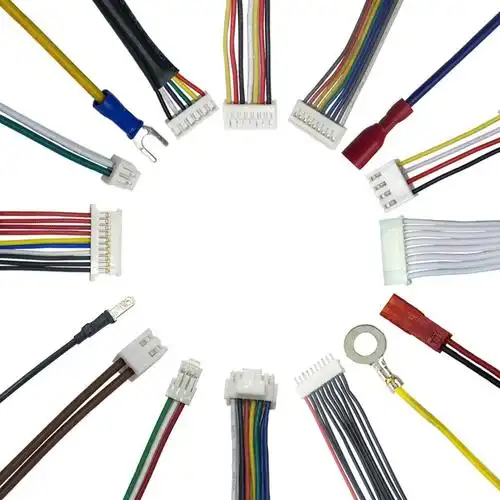
- Cables:
- Power (Welding Gun & Feeders): Opt for robust, high-flex welding cables with EPDM or similar heat-resistant insulation. Ensure adequate ampacity for the weld current and duty cycle.
- Control & Signals (I/O, Sensors, Encoders): Use highly flexible, shielded control cables with high strand counts for frequent bending. Shielded twisted pair (STP) or similar constructions are essential for noise immunity.
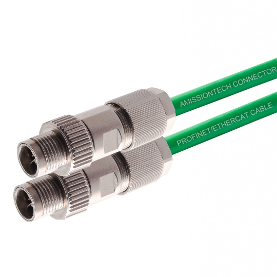
- Data (Ethernet, Fieldbus): Choose Industrial Ethernet (e.g., Cat6A) or ruggedized fieldbus cables with heavy braided shielding, PUR or TPE jacketing for oil/coolant resistance, and high flex-life ratings.
- Key Properties: Look for cables rated for continuous flexing, high temperature (often 90°C to 125°C+), oil/coolant resistance (e.g., PUR jacket), UV resistance, and verified EMI shielding effectiveness. Silicone insulation offers excellent heat resistance but is less abrasion-resistant.
- Connectors:
- Robustness: Metal-bodied connectors (e.g., M12, M8, Heavy Duty Industrial) are preferred over plastic. Ensure IP67/IP69K ratings for dust and water ingress protection, especially near the robot arm or gun.
- Locking: Positive locking mechanisms (screw, bayonet like M12, push-pull) are crucial to prevent vibration-induced disconnection.
- Shielding: Connectors must maintain cable shield continuity for EMI protection. Use connectors with integrated 360° shielding.
- Right-Angle Options: Often save space and reduce stress at connection points.
- Strain Reliefs/Bushings: Essential for protecting cable terminations from pulling and bending stresses. Use high-quality, clamp-style strain reliefs designed for the specific connector and cable diameter.
3. Design for Robustness and Longevity:
- Routing & Protection:
- Cable Carriers (Energy Chains): The cornerstone of robotic cable management. Choose the correct size, internal height, and type (open/closed) for the cable bundle. Ensure bend radius exceeds the cable/flexible carrier manufacturer’s minimum. Correct routing within the carrier is vital.
- Split Loom & Conduit: Use abrasion-resistant, flexible conduit (e.g., DR-25 double-walled) or high-temp split loom tubing to protect against sparks, slag, and sharp edges, especially outside cable carriers or in fixed runs.
- Avoid Pinch Points & Sharp Edges: Route cables away from moving parts and sharp features. Use protective edging on metal parts.
- Separation: Physically separate weld power cables from signal/data cables to minimize EMI coupling. Use different chambers within carriers or run them in separate paths when possible.
- Service Loops: Incorporate slack strategically at robot bases and fixed connection points to absorb movement without straining connections or exceeding bend radii. Ensure slack is neatly managed within carriers or loops.
- Heat Shielding: Utilize high-temperature sleeves or reflective tape in critical areas exposed to intense radiant heat.
4. Mitigating Electromagnetic Interference (EMI):
- Shielding is Mandatory: All cables carrying signals or data MUST have continuous, high-coverage shielding (braided > foil alone).
- 360° Shield Termination: Cable shields MUST connect cleanly and completely to connector bodies/shells. Use EMI backshells or proper shield termination techniques.
- Physical Separation: As mentioned in routing – maximize distance between weld power cables and sensitive cables. Cross at right angles if necessary.
- Ferrite Cores: Strategically placed snap-on ferrite chokes (especially near signal/drive ends) can help suppress high-frequency noise on communication lines or motor feeds.
5. Critical Considerations During Assembly & Installation:
- Professional Termination: Use proper crimping tools and techniques. Cold solder joints or poor crimps are failure points.
- Strain Relief: Correctly install strain reliefs to prevent pull forces on connector terminations.
- Secure Routing: Cable ties within carriers should be snug but not overtightened. Ensure cables move freely together without binding.
- Labeling: Clearly label cables and connectors at both ends for easy identification during maintenance.
- Testing: Conduct continuity checks, hi-pot testing (dielectric strength), and ideally signal integrity checks before installation into the cell.
6. Maintenance & Inspection Regime:
- Regular Visual Checks: Look for abrasion, burns, cracked insulation, damaged shielding, stressed connectors.
- Check Carrier Movement: Ensure carriers move freely without binding or dragging cables. Replace worn carriers.
- Monitor Cables in High-Wear Areas: Pay close attention to flex points, areas near the weld gun, and spots passing over edges.
- Preventative Replacement: Consider replacing critical cables proactively based on wear history or manufacturer flex-life ratings, before they fail catastrophically.
Conclusion:
Designing cable assemblies for robotic welding cells isn’t about finding the cheapest parts; it’s about selecting mission-specific components and implementing robust design strategies focused on protection, flexibility, EMI immunity, and reliability. Investing time and resources upfront in meticulous design, quality components, proper routing, and protective measures will result in cable assemblies that withstand the brutal environment, minimizing downtime and maximizing productivity over the long haul. Remember: The cable assembly is the lifeblood connecting your robot’s controls to its function – treat its design with the seriousness it deserves.