Military-Grade Coaxial Cable for Critical Applications
In applications where failure is not an option, such as military operations, aerospace systems, and certain industrial scenarios, military-grade coaxial cables are the go-to solution. These cables are engineered to meet the most demanding requirements, ensuring reliable performance in extreme conditions.
What Sets Military-Grade Coaxial Cables Apart?
Rugged Construction
Military-grade coaxial cables are built to withstand harsh environments. They have reinforced jackets that can resist physical damage from extreme temperatures, heavy moisture, and mechanical stress. For example, in military field operations, cables may be exposed to rough handling, temperature fluctuations from -65°C to +200°C, and wet conditions. The robust construction ensures the cable remains functional under these conditions.
Superior Shielding
Electromagnetic interference (EMI) and radio frequency interference (RFI) can disrupt signal transmission. Military-grade coaxial cables have multiple layers of shielding, such as braided wire and foil. This shielding protects the signals within the cable, maintaining stable communication even in high-noise environments like military bases with numerous electronic devices operating simultaneously.
High-Frequency Transmission
In military and aerospace applications, high-frequency signals are crucial for functions like radar systems and satellite communications. These cables are designed to handle high-frequency signals over long distances without significant signal degradation. They can maintain consistent signal integrity, with characteristics like precisely controlled impedance (usually 50Ω or 75Ω ± 0.5Ω across the operating frequency range) and low attenuation (often 50% lower than commercial equivalents at the same frequencies).
Compliance with Mil-Spec Standards
All military-grade coaxial cables must meet strict military specification (Mil-Spec) standards, such as Mil-C-17. These standards cover every aspect of the cable, from the materials used in conductors, dielectrics, shielding, and jacketing to construction techniques, dimensional tolerances, and rigorous testing methodologies. Meeting these standards ensures the cable can perform reliably in the challenging conditions of military use.
Common Types of Military-Grade Coaxial Cables
M17/75 – RG214
This widely used Mil-Spec coax cable offers excellent shielding and low signal loss. It is commonly found in radar systems, secure communication lines, and RF signal transmission. Its properties make it suitable for applications where a high level of signal integrity and protection against interference are required.
M17/60 – RG142
Known for its high resistance to environmental conditions, this cable effectively transmits signals at high frequencies. It is particularly useful in airborne systems and ground communication networks, where it can endure the vibrations, temperature changes, and other stresses associated with aircraft and field operations.
M17/128 – RG400
This cable is valued for its flexibility and resistance to harsh environments. It is frequently used in aircraft, ships, and other military vehicles for secure data transmission and maintaining signal integrity. Its flexibility allows for easier installation in the confined spaces of vehicles, while its durability ensures it can withstand the vibrations and mechanical stress experienced during transportation.
LMR – 400
Although not always Mil-Spec, LMR – 400 is a commonly used low – loss coaxial cable in military applications, especially for communication and signal relay in tactical settings. It offers a good balance of performance and cost – effectiveness, making it suitable for various field – based operations.
Choosing the Right Military – Grade Coaxial Cable
When selecting a military – grade coaxial cable for a critical application, several factors need to be considered:
- Application Requirements: Understand the specific needs of your application. For example, if it’s for a radar system, you need a cable that can handle high – frequency signals with low loss and good shielding. If it’s for a communication system in a vehicle, flexibility and ruggedness might be more important.
- Environmental Conditions: Consider the environment where the cable will be used. Extreme temperatures, humidity, vibration, and exposure to chemicals are all factors that can affect cable performance. Choose a cable with a construction and materials that can withstand these conditions.
- Connector Compatibility: Ensure that the cable you choose is compatible with the connectors used in your system. Mil – Spec connectors like N – type, SMA, or BNC are commonly used for their durability and shielding properties. Using the right connectors helps maintain signal integrity and prevent interference.
Installation and Maintenance
Proper installation and maintenance are crucial for the optimal performance of military – grade coaxial cables.
- Installation: In military vehicles, aircraft, and ships, cables should be routed to avoid vibration, temperature extremes, and mechanical wear. In military bases, the cabling infrastructure should be designed by electrical engineers to manage long – distance signal transmission for secure communications, radar systems, and surveillance. Cable routing, shielding, and grounding should be carefully planned to minimize interference and maximize reliability.
- Maintenance: Regular inspections should be carried out to check for any signs of damage, such as cuts in the jacket or loose connectors. Replace any damaged cables immediately to prevent signal degradation or failure. Additionally, keep the connectors clean and properly tightened to ensure good electrical contact.
Military – grade coaxial cables are essential for critical applications where reliable signal transmission is non – negotiable. By understanding their unique features, types, and how to select, install, and maintain them, you can ensure the success of your mission – critical systems.
What are the key factors in industrial cable performance?
Industrial cables are the “nerve system” of modern manufacturing, energy, and infrastructure—powering motors, transmitting control signals, and connecting critical equipment. Their performance directly impacts operational efficiency, safety, and downtime costs. For engineers, procurement teams, or facility managers searching to select or maintain industrial cables, understanding the core factors that define performance is essential to avoiding failures and optimizing system reliability. Below are the key elements that determine how well an industrial cable performs in real-world conditions.
1. Conductor Material and Design
The conductor is the backbone of any cable, responsible for carrying electrical current or signals. Its material and structure directly influence conductivity, current-carrying capacity, and long-term stability.
- Material Choice: Copper is the industry standard for most industrial applications due to its high electrical conductivity (97–100% IACS) and excellent ductility. Annealed copper (heat-treated to reduce brittleness) further enhances flexibility, making it ideal for cables that require frequent bending (e.g., robotic arms). Aluminum, while cheaper and lighter, has lower conductivity (61% IACS) and is prone to oxidation—requiring special coatings (e.g., tin-plating) for use in harsh environments.
- Stranding Design: Solid conductors (single, thick wire) offer low resistance but lack flexibility, suitable only for fixed installations (e.g., wall-mounted wiring). Stranded conductors (multiple thin wires twisted together) balance conductivity and flexibility; the number of strands (e.g., 7-strand, 19-strand) dictates how well the cable withstands repeated movement without breaking.
2. Insulation Layer Performance
Insulation acts as a barrier between the conductor and the environment, preventing electrical leakage, short circuits, and damage from external factors. Its performance is non-negotiable for safety and durability.
- Material Durability: Common insulation materials include PVC (polyvinyl chloride), XLPE (cross-linked polyethylene), and PTFE (polytetrafluoroethylene). PVC is cost-effective for general-purpose use but struggles at temperatures above 70℃. XLPE, with its cross-linked molecular structure, resists heat (-50℃ to 90℃), chemicals, and moisture—making it ideal for oil & gas or wastewater treatment plants. PTFE (Teflon) offers extreme temperature resistance (-200℃ to 260℃) for high-heat applications like industrial ovens.
- Thickness and Uniformity: Insulation thickness must meet industry standards (e.g., IEC, UL) to handle the cable’s rated voltage. Uneven insulation (a result of poor manufacturing) creates weak points where electrical breakdown or physical damage is likely to occur.
3. Shielding Effectiveness
Industrial environments are filled with electromagnetic interference (EMI) from motors, variable frequency drives (VFDs), and radio equipment. Unshielded cables pick up this interference, distorting signals or disrupting power delivery—critical issues for automation and control systems.
- Shielding Types: The most effective shielding options include:
- Braid Shielding: Woven copper or aluminum strands that block 85–95% of EMI. It is flexible, making it suitable for moving cables (e.g., conveyor systems).
- Foil Shielding: Thin aluminum-polyester tape that provides 100% coverage (ideal for low-frequency interference) but is less durable than braiding.
- Dual Shielding: A combination of foil and braid, offering maximum protection for sensitive applications (e.g., PLC control signals, medical equipment in industrial settings).
- Grounding: Proper grounding of the shield is required to channel intercepted EMI away from the cable—without it, the shield itself can become a source of interference.
4. Structural Integrity (Jacket and Reinforcement)
The outer jacket (or sheath) and additional reinforcement protect the cable from mechanical damage, abrasion, and environmental stress. This is especially critical for cables installed in high-traffic areas or outdoor settings.
- Jacket Material: Like insulation, jacket materials are chosen for their resilience. Polyurethane (PU) jackets resist oil, grease, and abrasion—perfect for factory floors with heavy machinery. Polyethylene (PE) jackets are UV-stabilized, making them suitable for outdoor use (e.g., solar farms, construction sites).
- Reinforcement: For cables exposed to extreme tension (e.g., overhead cranes) or crushing forces (e.g., under forklifts), reinforcement layers (e.g., steel wire armor, aramid fibers) add strength without sacrificing flexibility.
5. Environmental Resistance
Industrial cables operate in diverse, harsh conditions—from freezing warehouses to corrosive chemical plants. A cable’s ability to withstand these environments directly impacts its lifespan.
- Temperature Extremes: Cables rated for “low-temperature flexibility” use materials that remain pliable in cold conditions (e.g., -40℃ for outdoor winter applications), while high-temperature cables rely on heat-resistant insulation/jackets (as noted in Section 2).
- Moisture and Corrosion: Water or chemicals can degrade conductors and insulation over time. Cables with water-blocking tape (for moisture) or chemical-resistant jackets (e.g., EPDM rubber for acids) are essential for wet or corrosive environments.
- UV Exposure: Outdoor cables require UV-stabilized jackets to prevent brittleness and cracking from prolonged sun exposure.
Why These Factors Matter: Beyond “Working” Cables
A cable that merely “works” is not enough for industrial operations. Poorly performing cables lead to unplanned downtime (costing $50,000–$500,000 per hour for manufacturing plants), safety hazards (e.g., electrical fires), and increased maintenance costs. By prioritizing conductor quality, insulation durability, shielding, structural integrity, and environmental resistance, teams can select cables that match their specific application needs—ensuring long-term reliability.
When it comes to industrial cables built for performance, FRS brand factory stands out as a trusted partner. FRS integrates all the key performance factors into every product: using high-purity annealed copper for conductors, premium XLPE/PTFE for insulation, and dual shielding for EMI protection. Each cable undergoes rigorous testing—from voltage breakdown checks to temperature cycling—to ensure it withstands the harshest industrial environments. Whether you need cables for automation, oil & gas, or outdoor infrastructure, FRS delivers consistent quality that minimizes downtime and maximizes safety. Choose FRS for cables that don’t just perform—they endure.
Custom Industrial Ethernet Cable Assemblies Manufacturer (FRS)
FRS specializes in providing industrial-grade Ethernet cable assemblies for PLCs, robots, HMIs, and Industry 4.0 equipment. Our robust components merge standard Ethernet principles with durable connectors, making them ideal for automated control in harsh industrial environments.
Why Standard Ethernet Cables Fall Short
Standard office-grade Ethernet cables are not built for the realities of industrial automation. In a typical plant, cables face constant vibration, bending, abrasion, exposure to oils, coolants, and welding splatter, along with electromagnetic interference (EMI) from drives and motors.
Using the wrong cable can lead to:
- Intermittent Communication:Causing system faults and unplanned downtime.
- Data Corruption:Leading to inaccurate measurements and product defects.
- Signal Loss:Resulting in reduced network speed or complete failure.
- Frequent Replacements:Increasing long-term maintenance costs.
An industrial-grade solution is non-negotiable for stable plant-floor connectivity.
FRS as Your Industrial Ethernet Cable Assemblies Manufacturer
As a professional Industrial Ethernet Cable Assemblies Manufacturer, FRS delivers custom-engineered solutions. We combine standard Ethernet technology with industrial-grade materials and connectors to ensure reliable data transmission in demanding applications.
Our cables are designed to meet the mechanical, electrical, and environmental demands of industrial automation.
Key Applications
1. PLC to HMI / Control Cabinet Links
Stable communication between PLCs and HMIs is mission-critical. Downtime here can halt an entire production line.
- Cable Construction:Typically shielded twisted-pair (Cat5e/Cat6/Cat6A) with PUR, TPE, or LSZH jackets.
- Connector Options:RJ45, M12 (D-coded, X-coded), or M8 for tight spaces.
- FRS Advantage:We design assemblies for high-flex or drag-chain use, ensuring reliable performance in control cabinets, cable tracks, or along moving machine axes.
2. Robotics and Motion Control
Robotics involve high-speed, high-flex motion, making cable reliability a top priority.
- Challenges:Cables must withstand millions of bending cycles, torsion, and tight bend radii.
- FRS Advantage:We use high-flex stranded conductors, optimized shielding, and robust overmolding. Our assemblies are validated for continuous flex, torsion, and drag-chain tests, ensuring they last as long as the robot.
3. Industrial 4.0 and IIoT Gateways
IIoT environments require reliable data links for sensors, gateways, and edge devices.
- Protocol Support:Our cables are built to support EtherCAT, PROFINET, Modbus TCP, and standard TCP/IP.
- FRS Advantage:We provide assemblies that maintain signal integrity across multiple switches and long cable runs, ensuring your data is clean and timely for analytics and predictive maintenance.
Engineering & Customization
We believe one size does not fit all. Our engineering team works with you to create the optimal cable for your specific application.
- Connector:RJ45, M12 (D/X-coded), M8, ix Industrial, or custom metal shells.
- Cable Type:Cat5e, Cat6, Cat6A, or Single Pair Ethernet (SPE) based on speed and distance needs.
- Shielding:UTP, FTP, SF/UTP, or S/FTP, selected based on EMI levels.
- Jacket:PVC, PUR, TPE, or LSZH, chosen for environmental resistance and flexibility.
- Mechanical:We specify bend radius, flex life, and torsion resistance for dynamic applications.
- Environmental:We consider temperature, oil, UV, and chemical resistance.
- Compliance:We ensure our designs meet relevant standards like UL, CE, RoHS, and industry-specific ones (e.g., PROFINET).
Quality Assurance
Quality is not an afterthought; it’s our foundation. As a professional Industrial Ethernet Cable Assemblies Manufacturer, we implement rigorous quality control.
- Incoming Material Control:We audit and test all raw materials.
- In-Process Testing:We perform 100% electrical tests (continuity, hipot) and sample-based mechanical tests (flex, bend, torsion).
- Standards Compliance:We test to TIA/EIA and ISO/IEC standards, using tools like the Fluke DSX Series for certification.
- Documentation:We provide test reports and traceability for every batch.
Why Partner with FRS
Choosing the right Industrial Ethernet Cable Assemblies Manufactureris a strategic decision. Here’s why global automation companies choose FRS:
- Deep Application Knowledge:We understand the demands of industrial networks, from the shop floor to the cloud.
- Customization, Not Just Standard Products:We provide tailored solutions, not off-the-shelf compromises.
- Proven Reliability:Our cables are built to perform reliably for years, reducing your total cost of ownership.
- Responsive Support:We offer fast communication and engineering support to keep your projects on schedule.
- Scalable Manufacturing:Our robust production ensures consistent quality, whether you need a small prototype run or high-volume OEM orders.
Your Next Step
Stop risking your automation performance to inferior cables. Let our team at FRS be your trusted Industrial Ethernet Cable Assemblies Manufacturer.
Contact us todayto discuss your specifications or request a customized quotation. We will work with you to engineer a solution that ensures reliable connectivity and maximum uptime for your industrial systems.
Contact Us Right Now:
TEL&WECHAT: +86-1881-875-005 (Wechat)
E-MAIL: sales@custom-cable-assemblies.com
New Multi-layer Shielding Camera Link Cable Boosts Machine Vision System Stability
In high-precision machine vision applications, even a minor cable issue can lead to image artifacts, data loss, and costly downtime. As resolutions, frame rates, and system complexity increase, the Multi-layer shielding Camera Link cablehas become essential for ensuring stable, long-term operation. This article explores the critical role of advanced shielding, its impact on system stability, and how to select the right cable for your application.
🎯 Why Signal Stability is Non-Negotiable
Camera Link is a mature, high-bandwidth standard for industrial cameras, supporting data rates up to 5.44 Gbit/s in Base/Medium/Full configurations and 6.8 Gbit/s in Deca mode. It’s widely used in electronics inspection, automotive, and logistics. However, its high-speed differential signaling is highly sensitive to interference and impedance mismatches.
Common Field Issues:
- Intermittent Artifacts:Sparkling pixels or horizontal stripes, often linked to EMI/RFI or poor shielding.
- Frame Loss & Triggers:Dropped frames or missed triggers caused by signal jitter or skew.
- System Crashes:Image acquisition software freezes due to data corruption on the link.
These problems often trace back to the cable, especially in electrically noisy factory environments with motors, VFDs, and long cable runs.
🛡️ The Multi-Layer Shielding Architecture
A robust Multi-layer shielding Camera Link cableis designed to combat interference through a synergistic structure:
- Individual Pair Shielding:Each twinax pair is wrapped in its own aluminum foil, minimizing crosstalk and interference between pairs carrying high-speed video data.
- Overall Foil Shield:A second layer of aluminum foil encapsulates the entire bundle of pairs, providing a second barrier against external noise.
- Braided Shield:A tinned copper braid offers >80% coverage, acting as a low-impedance path to ground for high-frequency noise.
- Drain Wires:Integrated wires connect the inner and outer shields to the connector backshell, ensuring a controlled path for induced currents and preventing ground loops.
- Twisted Pair Geometry:Precise pair twisting maintains constant impedance and reduces susceptibility to magnetic fields.
This multi-layered defense is crucial for maintaining signal integrity in demanding industrial settings.
⚡ How Shielding Enhances System Stability
The benefits of multi-layer shielding translate directly into tangible performance improvements:
- Reduced EMI/RFI Susceptibility:Shielding protects image data from corruption by strong electromagnetic fields near motors or welders, ensuring clean images and reliable measurements.
- Lower Bit Error Rates (BER):By minimizing reflections and interference, multi-layer shielding reduces data errors, preventing frame drops and corrupted inspections.
- Consistent Signal Timing:Precise construction controls impedance and skew, which is vital for multi-camera systems requiring microsecond-level synchronization.
- Longer Cable Runs:High-quality shielding allows for stable operation at the upper limits of the Camera Link standard (e.g., 10–15m for Base/Medium/Full), reducing the need for costly repeaters or fiber conversions.
🔧 Key Cable Specifications to Evaluate
When selecting a Multi-layer shielding Camera Link cable, consider the following parameters:
- Conductor & AWG:Look for fine-stranded, tinned copper conductors (e.g., 28AWG) for flexibility and low resistance.
- Shielding Construction:Opt for cables specifying individual pair foil, overall foil, and braided shielding with high coverage (>80%).
- Impedance & Skew:Ensure the cable is specified for 100 Ω differential impedance and has controlled skew for your operating mode.
- Jacket & Environmental Rating:Choose an oil-resistant, flame-retardant jacket (e.g., PVC, PUR) with an operating temperature range that matches your environment (e.g., -20°C to +80°C).
- Connector & Locking:Use MDR/SDR connectors with thumbscrew locks for a secure, vibration-resistant connection. Right-angle options save space in tight enclosures.
- PoCL Compatibility:For Power-over-Camera Link (PoCL) applications, ensure the cable is specifically designed and certified for PoCL to handle the combined power and data load safely.
🏭 Matching Cables to Your Application
Different applications place different stresses on cables. Here’s a guide to common scenarios:
| Application Scenario | Key Challenges | Cable Features |
|---|---|---|
| Robotics & Motion | Constant flexing, vibration, tight spaces | High-flex conductors, durable jacket (PUR/TPE), right-angle connectors, robust shielding. |
| Electrically Noisy Factory Floors | High EMI/RFI from motors, VFDs | Maximum shielding (foil + braid), proper grounding, separation from power cables. |
| Multi-Camera & 3D Systems | Precise timing, long runs, cable management | Low skew, excellent shielding, length-matched cables, robust connectors. |
| Harsh Environments | Exposure to oil, coolant, dust, temperature extremes | Oil-resistant, chemical-resistant jacket, wide temperature range, IP-rated connectors. |
🏢 Why FRS is Your Trusted Partner for Camera Link Cables
For over 20 years, FRShas been a specialist in high-performance cable assemblies, including Camera Link. Our expertise ensures your vision systems are built on a solid foundation.
- Proven Manufacturing:We are a dedicated factory with extensive experience in producing LVDS, micro-coaxial, and Camera Link cables, ensuring top-tier quality.
- Rigorous Quality Control:Every cable undergoes a 100% electrical performance test, guaranteeing signal integrity and reliable operation from day one.
- Full Customization:We provide tailored solutions, from standard lengths to complex harnesses, with custom connectors, shielding, and labeling to meet your exact specifications.
- Global Certifications:Our products meet international standards like RoHS, CE, ISO9001, IATF16949, and UL, making them suitable for demanding global projects.
🚀 Ready to Upgrade Your Vision System?
Stop compromising on cable quality. A high-quality Multi-layer shielding Camera Link cableis a long-term investment in stability, yield, and reduced downtime.
Contact FRS todayto discuss your specific Camera Link cabling needs. Our engineering team is ready to provide a customized solution that ensures your machine vision system performs reliably in even the harshest industrial environments.
2026 New Release: High-flex Mini-change Industrial Cable Assemblies for Robotics Applications
As robotics and high-flex automation evolve, the need for reliable, high-flex Mini-change industrial cable assemblies has never been greater. This 2026 guide explores the essential features, applications, and selection criteria for Mini-change (7/8”) cable assemblies, with a focus on robotic systems.
Why Robotics Demands High-Flex Mini-Change Cable Assemblies
Modern robotics, from industrial robot arms and cobots to humanoid robots and AGVs, require cable assemblies that can withstand constant, multi-axis motion, tight bend radii, and exposure to oils, coolants, and dust. Standard cables in these dynamic environments often fail due to broken conductors, cracked jackets, or loose connectors, leading to downtime and maintenance costs.
High-flex Mini-change cable assemblies are purpose-built for these challenges. They combine the robust, industry-standard Mini-change (7/8”) connector familywith high-flex cablesengineered for millions of flex cycles. This results in:
- Enhanced Robot Performance: Smoother, more reliable movement in articulated arms, SCARA, and delta robots.
- Extended Service Life: Reduced cable fatigue and failure in cable chains and rotating joints.
- Simplified Integration: A robust and standardized interconnect solution for power and signal transmission.
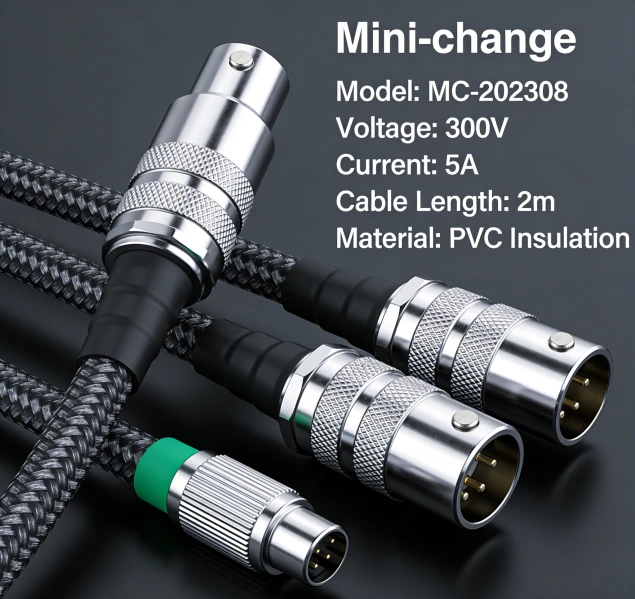
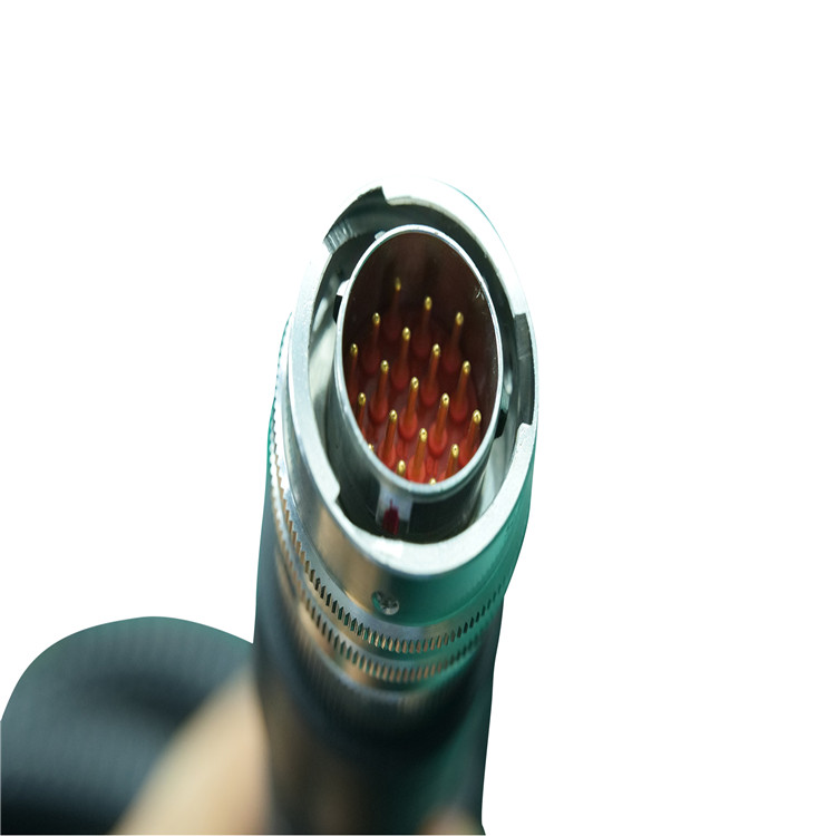
Understanding Mini-Change (7/8”) Connectors
Mini-change connectors, also known as 7/8” circular connectors, are a rugged, sealed solution for industrial power and signal transmission. Key characteristics include:
- Standardized & Interchangeable: The 7/8”-16UN thread and industry-standard codings ensure easy integration and replacement.
- Robust & Sealed: Typically rated at least IP67, with some versions reaching IP68/IP69K, they protect against dust and water ingress, even in high-pressure washdown environments.
- High Current & Voltage: Available in 2 to 19 poles, they support significant power delivery. For example, Molex Mini-Change cordsets can handle 8–13 A per contactand 300–600 V, depending on the series and cable.
Common Configurations
- Coding & Poles: Available in A, B, and other codings for power or signal. Pole options range from 2 to 19, with common configurations for 3, 4, 5, and 8-pin setups.
- Cable Materials: Choose from PVC, PUR, TPE, or WSORjackets, selected based on environmental needs like oil resistance, flex life, or high-temperature performance.
- Assembly Types: Offered as single-ended cordsets, double-ended extension cables, or field-wireable connectors for on-site termination.
Key Features of High-Flex Mini-Change Assemblies for Robotics
A high-flex Mini-change cable assembly integrates a flexible cable with robust Mini-change connectors, designed for dynamic robotic applications.
1. High-Flex Cable Construction
These cables are built to last, featuring design elements crucial for robotics:
- Fine-Stranded Conductors: Maximize flexibility and fatigue resistance.
- Optimized Twisting & Layering: Ensures stability and prevents tangling during constant motion.
- Dedicated Tensile Elements: A central support structure enhances flex life and protects against breakage.
- Durable Jacket Materials: PUR, TPE, or WSORjackets provide excellent oil, abrasion, and tear resistance, ideal for industrial settings.
2. Rugged Connectors & Strain Relief
The connection points are reinforced to handle stress:
- Robust Housings: Made from impact-resistant materials like zinc die-cast, with options for epoxy coating to prevent corrosion.
- High-Quality Contacts: Gold-plated brass or phosphor bronze contacts ensure low contact resistance and reliable connections.
- Effective Sealing: O-rings and precision-machined threads maintain the IP67/IP68 rating, even under vibration.
- Integrated Strain Relief: Molds or overmolding at the cable-entry point protects the conductor-crimp junction from bending forces.
3. Environmental & EMI Protection
Robotic systems demand robust protection:
- Mechanical Protection: Abrasion-resistant jackets and optional armored or stainless-steel braid protect against physical damage.
- Chemical & Temperature Resistance: Jackets are selected based on exposure to coolants, oils, and operating temperatures (e.g., -40°C to +90°C).
- EMI Shielding: Tinned copper braid or foil shields with high coverage (e.g., >80%) are used for signal and data cables to prevent electromagnetic interference.
4. Flex Life & Performance Validation
Reliable manufacturers validate performance through rigorous testing:
- Flex Life Testing: Cables are tested for millions of cycles in bending or torsion machines that simulate real-world robot motion.
- Environmental Stress Testing: Includes temperature cycling, oil immersion, and chemical exposure tests.
- Electrical Performance Verification: Ensures stable contact resistance and high-voltage isolation after mechanical stress.
Typical Robotics Applications
High-flex Mini-change assemblies are ideal for various robotic and automation systems:
- Industrial Robot Arms: Powering and signaling servo motors, encoders, and end-effectors.
- Collaborative Robot (Cobot) Joints: Connecting joints with compact, shielded power and signal cables.
- Humanoid & Mobile Robots: Used in legs, arms, and sensor arrays where space and weight are critical.
- Automated Guided Vehicles (AGVs): Connecting navigation, battery, and control systems in dynamic environments.
- Robotic Vision Systems: Transmitting power and high-speed data for 3D cameras and laser scanners.
How to Specify the Right Assembly
To choose the optimal high-flex Mini-change cable assembly, consider the following factors:
- Voltage & Current: Determine the voltage and current per contact to select the appropriate pole count and wire gauge (e.g., 18–16 AWG).
- Signal or Data Requirements: Choose shielded twisted pairs for data or bus systems (e.g., DeviceNet, CC-Link). For power, focus on ampacity and jacket robustness.
- Environmental Conditions: Consider exposure to coolants, oils, high-pressure washdown, and temperature extremes to select the right jacket material (PVC, PUR, TPE, WSOR) and IP rating.
- Mechanical Motion: Analyze the robot’s motion profile (bending radius, torsion, speed) to determine the necessary flex life and cable type.
- Connector Details: Specify the exact connector type (male/female, straight/angled), coding (A/B), and pole count.
- Cable Length & Routing: Account for bend radii and potential cable slack to prevent overstressing the assembly.
Your Trusted Partner: RFS – High-Flex Mini-Change Cable Assemblies
RFS is a specialist in high-flex Mini-change industrial cable assemblies, dedicated to robotics and automation. Our 2026 new release features enhanced designs for longer flex life, improved chemical resistance, and optimized shielding effectiveness.
We provide comprehensive, end-to-end solutions:
- Custom Design & Prototyping: Our engineers work with your CAD models and motion profiles to create optimized assemblies.
- Rigorous Testing & Validation: We offer testing for flex life, environmental resistance, and electrical performance, providing full documentation.
- Scalable Manufacturing: From prototypes to high-volume production, our ISO-quality manufacturing ensures consistent quality and fast turnaround times.
Contact RFS todayto discuss your robotics project and discover how our high-flex Mini-change cable assemblies can enhance your system’s reliability and performance.
Contact Us Right Now:
E-MAIL: sales@custom-cable-assemblies.com
Industrial Cable Assemblies | Automation & Control
In the high-stakes environment of modern industrial automation, the difference between seamless production and catastrophic downtime often comes down to a single component: the connection. While controllers, sensors, and actuators get most of the attention, Industrial Cable Assembliesare the nervous system that allows data and power to flow reliably. In automation and control systems, these are not merely wires; they are precision-engineered solutions designed to withstand extreme conditions while maintaining signal integrity.
This article moves beyond basic definitions to explore how advanced cable assemblies are solving today’s most complex challenges in factory automation, robotics, and process control.
The Hidden Cost of Standard Cables in Automation
Many engineers initially opt for standard off-the-shelf cables to save costs. However, in an industrial setting, this approach often backfires. Standard cables lack the robust shielding, strain relief, and environmental resistance required for long-term reliability.
An underperforming cable assembly can lead to:
- •Signal Degradation:Data errors in communication protocols like Ethernet/IP or Profinet.
- •Unplanned Downtime:Failures caused by constant flexing, abrasion, or chemical exposure.
- •Safety Hazards:Insulation breakdown in high-temperature or high-voltage environments.
For mission-critical applications, investing in purpose-built Industrial Cable Assembliesis not an expense—it is risk mitigation.
Key Applications in Automation & Control Systems
Understanding where and why specific assemblies are used is crucial for selecting the right solution.
1. Robotic Arm Connectivity (Continuous Flex)
Robotic arms in welding or assembly lines undergo millions of bend cycles. Standard cables will fail within weeks.
- •Requirement:High-flex (CF) cables with stranded, fine-wire conductors and torsionally balanced designs.
- •Solution:Assemblies with PUR (Polyurethane) jackets offer superior oil resistance and flexibility, preventing conductor fatigue.
2. Industrial Ethernet & Data Communication
The rise of IIoT (Industrial Internet of Things) demands flawless data transmission.
- •Requirement:Impedance control and EMI (Electromagnetic Interference) shielding.
- •Solution:Cat5e, Cat6A, or fiber optic assemblies with dual shielding (braid + foil) to protect against interference from high-voltage motor drives and variable frequency drives (VFDs).
3. Sensor and Actuator Integration
Connecting proximity sensors, limit switches, and pneumatic valves requires compact yet durable connections.
- •Requirement:Space-saving designs that resist coolants and cutting oils.
- •Solution:Valve connector cables (e.g., M8, M12, 7/8″) with overmolded connectors and robust PVC or TPE jackets.
Engineering Beyond the Basics: What Separates Premium Assemblies
To truly outperform competitors, one must look at the technical nuances that generic suppliers overlook.
Material Science Matters
The jacket material dictates performance. Choosing incorrectly is a common pitfall.
- •PVC:Cost-effective but stiff and prone to cracking in cold temperatures.
- •PUR (Polyurethane):Excellent abrasion, oil, and chemical resistance. Remains flexible in extreme cold.
- •TPE (Thermoplastic Elastomer):Combines the flexibility of rubber with the processing ease of plastic; ideal for drag chains.
Advanced Shielding Techniques
Not all shielding is created equal. For VFD applications, “100% shield coverage” is a myth. Effective shielding uses a combination of:
- •Aluminum Foil:For high-frequency noise rejection.
- •Tinned Copper Braid:For low-frequency noise and grounding continuity.A premium assembly will specify the percentage of braid coverage (e.g., 85%) rather than using vague marketing terms.
Overmolding vs. Traditional Assembly
Traditional assemblies use heat shrink or hand-applied strain relief, which can create failure points.
- •Overmolding:Injects molten plastic directly onto the connector and cable, creating a permanent, watertight bond. This eliminates ingress points for dust and moisture (achieving IP67 or IP68 ratings) and provides superior pull strength.
Selection Guide: Matching Cable Specs to Your Environment
When specifying Industrial Cable Assembliesfor automation, use this checklist:
| Environmental Factor | Required Specification | Why It Matters |
|---|---|---|
| Oil & Coolant Exposure | PUR Jacket, IP67 Rating | Prevents jacket swelling and insulation breakdown. |
| Continuous Motion | High-Flex Rated, Stranded Conductors | Prevents copper wire fatigue and internal breaks. |
| High EMI/VFD Noise | Dual-Shielded (Foil + Braid) | Maintains signal integrity for analog and data lines. |
| Extreme Temperatures | Silicone or PTFE Insulation | Ensures flexibility in freezers (-40°C) or near furnaces (+105°C). |
Future Trends: Smart Cables and Predictive Maintenance
The next evolution in Industrial Cable Assembliesis the integration of intelligence. We are seeing the emergence of “smart cables” with embedded micro-chips or diagnostic fibers. These allow for:
- •Real-time Monitoring:Tracking bend cycles, temperature, and signal quality.
- •Predictive Alerts:Notifying maintenance teams of impending failures before they cause line stops.
As automation systems become more complex, the demand for cables that can communicate their own health status will surge.
Conclusion
In the realm of automation and control, treating cable assemblies as an afterthought is a recipe for failure. By understanding the specific demands of your application—from robotic flex life to EMI shielding—you can select assemblies that enhance reliability and reduce total cost of ownership. High-quality Industrial Cable Assembliesare not just a component; they are the foundation of a resilient and efficient automated system.
Global Fire-Resistant Cable Standards Launched
Introduction
In a landmark move to enhance fire safety across industries, international regulatory bodies have introduced updated Global Fire-Resistant Cable Standards. These standards aim to minimize fire risks, improve electrical safety, and ensure uniformity in cable manufacturing and installation worldwide. With fires caused by faulty wiring accounting for [statistical data, e.g., “20% of commercial building fires”], this initiative addresses a critical gap in global infrastructure safety. Here’s an in-depth look at what the new standards entail and how they impact industries, businesses, and consumers.
Why Fire-Resistant Cables Matter
Fire-resistant cables are engineered to maintain circuit integrity during fires, allowing critical systems (e.g., emergency lighting, alarms, and ventilation) to function even under extreme heat. Traditional cables often fail under high temperatures, exacerbating fire-related disasters. The new global standards prioritize:
- Extended Circuit Integrity: Cables must withstand fire exposure for 90–120 minutes, up from previous 30–60-minute benchmarks.
- Low Smoke and Toxicity: Compliance with IEC 60754 and EN 50399 for reduced smoke emission and halogen-free materials, protecting human health during evacuations.
- Global Consistency: Harmonizing regional standards (e.g., NEC in the U.S., BS in the UK, and IEC internationally) to simplify compliance for multinational projects.
Key Features of the New Standards
- Enhanced Testing Protocols
- Cables must pass rigorous fire resistance, vertical flame spread, and water spray tests to simulate real-world fire scenarios.
- Mandatory third-party certification from bodies like UL Solutions, TÜV SÜD, or Intertek.
- Material Requirements
- Use of ceramic-forming compounds or mica-based insulation to withstand temperatures exceeding 1,000°C.
- Ban on PVC in high-risk environments due to toxic fumes.
- Application-Specific Guidelines
- Stricter rules for high-rise buildings, tunnels, oil and gas facilities, and public transport systems (e.g., metros and airports).
Impact on Industries
- Construction and Infrastructure
- Architects and contractors must specify compliant cables in new projects. Retrofitting older buildings may become mandatory in fire-prone regions.
- Cost implications: Fire-resistant cables cost 15–30% more than standard ones, but insurers may offer reduced premiums for compliant installations.
- Energy and Manufacturing
- Power plants, factories, and renewable energy sites (e.g., solar/wind farms) will need to upgrade cabling to avoid operational downtime during inspections.
- Consumer Electronics
- Appliances and EV charging stations must integrate certified cables to meet safety regulations.
Steps to Ensure Compliance
- Audit Existing Installations: Identify non-compliant cables in high-risk zones.
- Partner with Certified Suppliers: Source cables bearing IEC 60331, BS 6387, or NFPA 262 certifications.
- Train Workforce: Educate electricians and engineers on proper installation techniques for fire-resistant systems.
Future Outlook
The global fire-resistant cable market, valued at [e.g., “$2.1 billion in 2023”], is projected to grow at 8.5% CAGR as regulations tighten. Innovations like smart fire-resistant cables with embedded sensors for real-time hazard detection are already in development.
Engineers Predict 2025 Cable Trends
The cable industry, a backbone of modern technology, is poised for transformative changes by 2025. Engineers and industry experts are forecasting advancements driven by sustainability, digitalization, and evolving infrastructure demands. Below, we explore the top trends shaping the future of cable technology, designed to enhance SEO visibility and provide actionable insights for professionals.
1. Sustainable Materials and Eco-Friendly Design
- Key Drivers: Regulatory pressures (e.g., EU Green Deal) and consumer demand for circular economy practices.
- Trend: Biodegradable insulation, recycled copper, and low-carbon manufacturing processes will dominate R&D.
- SEO Keywords: “Eco-friendly cables,” “sustainable wire materials,” “green infrastructure.”
2. Smart Cable Integration with IoT and AI
- Innovation: Embedded sensors and real-time monitoring systems to detect faults, temperature fluctuations, and energy loss.
- Applications: Power grids, industrial machinery, and EV charging stations.
- SEO Keywords: “Smart cables IoT,” “AI-driven cable solutions,” “predictive maintenance.”
3. High-Temperature Superconducting (HTS) Cables
- Breakthrough: HTS cables transmit electricity with zero resistance, reducing energy waste.
- Use Cases: Urban power grids, renewable energy storage, and long-distance transmission.
- SEO Keywords: “HTS cables,” “superconducting technology,” “energy-efficient power lines.”
4. 5G/6G-Ready Infrastructure and High-Speed Data Cables
- Demand: 5G expansion and emerging 6G networks require ultra-low-latency, high-bandwidth cables.
- Trend: Fiber-optic cables with increased core density and lightweight designs.
- SEO Keywords: “5G cable infrastructure,” “6G-ready cables,” “data transmission innovation.”
5. Miniaturization and Flexible Cable Solutions
- Focus Areas: Medical devices, wearable tech, and robotics need bendable, durable cables.
- Materials: Liquid crystal polymers (LCPs) and graphene-enhanced coatings.
- SEO Keywords: “Flexible cables,” “miniaturized wiring,” “wearable technology cables.”
6. Space and Undersea Cable Advancements
- Space: Radiation-resistant cables for lunar/Mars habitats and satellite systems.
- Undersea: Robust cables for offshore wind farms and transoceanic internet links.
- SEO Keywords: “Space cables,” “undersea fiber optics,” “renewable energy infrastructure.”
7. Cybersecurity-Enhanced Cables
- Rising Threat: Physical cable hacking in critical infrastructure.
- Solution: Tamper-proof coatings, encrypted signal transmission, and self-healing materials.
- SEO Keywords: “Cable cybersecurity,” “secure data transmission,” “infrastructure protection.”
8. Cost Optimization Through Additive Manufacturing
- Trend: 3D-printed cable components to reduce production time and material waste.
- Impact: Customized designs for niche industries like aerospace and automotive.
- SEO Keywords: “3D-printed cables,” “additive manufacturing,” “cost-effective cable production.”
IoT-Compatible Cables Hit Mainstream
The Internet of Things (IoT) is no longer a futuristic concept—it’s reshaping industries, homes, and cities. From smart thermostats to industrial sensors, billions of IoT devices are now online. But as the IoT ecosystem grows, so does the demand for reliable infrastructure, particularly IoT-compatible cables. These specialized cables are now hitting the mainstream, addressing critical challenges in connectivity, power efficiency, and durability. In this article, we explore why IoT-compatible cables matter, their key features, and how to choose the right ones for your needs.
Why IoT-Compatible Cables Are Becoming Essential
The IoT landscape relies on seamless data transmission and uninterrupted power supply. Standard cables often fall short due to:
- Higher Data Bandwidth Requirements: IoT devices transmit vast amounts of data, especially in applications like 4K security cameras or real-time industrial monitoring.
- Power-over-Ethernet (PoE) Needs: Many IoT systems use PoE to simplify installations, requiring cables to deliver both power and data.
- Harsh Environmental Conditions: Outdoor or industrial IoT devices need cables resistant to moisture, temperature fluctuations, and EMI (electromagnetic interference).
According to a 2023 report by Grand View Research, the global IoT market is projected to grow at a 19.4% CAGR through 2030, driving demand for rugged, high-performance cables optimized for smart ecosystems.
Key Features of IoT-Compatible Cables
Not all cables are created equal. Here’s what sets IoT-compatible cables apart:
- Enhanced Shielding
- Shielded twisted-pair (STP) or foil-shielded designs minimize EMI/RFI interference, ensuring signal integrity in environments crowded with wireless devices.
- PoE Support
- Cables like Cat6a and Cat7 support higher wattage (up to 100W for PoE++), critical for powering devices like PTZ cameras or access points without additional wiring.
- Durability
- Industrial-grade IoT cables feature UV-resistant jackets, waterproofing (IP67 ratings), and corrosion-resistant materials for outdoor or factory use.
- Flexibility and Size
- Compact, lightweight designs (e.g., 28AWG cables) are ideal for tight spaces in smart homes, robotics, or automotive IoT installations.
- IoT-Specific Certifications
- Look for certifications like UL 444 for communications cables or IEC 61156 for data transmission performance.
Top Applications Driving Adoption
IoT-compatible cables are finding use across sectors:
- Smart Buildings: PoE cables power LED lighting, HVAC systems, and occupancy sensors.
- Industrial IoT (IIoT): Rugged Cat6a cables connect machinery sensors for predictive maintenance.
- Healthcare: Medical-grade cables ensure reliable connectivity for patient monitoring devices.
- Agriculture: Weatherproof cables link soil sensors and irrigation systems in smart farms.
How to Choose the Right IoT-Compatible Cable
- Assess Bandwidth Needs:
- Use Cat6 (250MHz) for basic IoT devices; upgrade to Cat6a (500MHz) or Cat7 (600MHz) for high-speed industrial applications.
- Check Power Requirements:
- For PoE devices, ensure cables meet IEEE 802.3bt (PoE++) standards for up to 100W power delivery.
- Prioritize Environmental Resistance:
- Opt for polyethylene jackets for outdoor use or plenum-rated cables for HVAC spaces.
- Future-Proofing:
- Invest in higher-tier cables (e.g., Cat7) to accommodate future IoT upgrades.
The Future of IoT Cabling
As IoT networks expand, next-gen innovations are emerging:
- Fiber Optic Integration: Hybrid cables combining copper and fiber for ultra-long-distance data transfer.
- Smart Cables: Embedded sensors to monitor cable health and predict failures.
- Standardization: Organizations like TIA and ISO are developing IoT-specific cabling standards to streamline adoption.
FAQs
Q: Can I use regular Ethernet cables for IoT devices?
A: Basic Cat5e cables work for low-power IoT devices, but PoE-heavy or high-bandwidth systems require Cat6a or higher.
Q: What’s the maximum distance for IoT-compatible cables?
A: Standard Ethernet runs up to 100 meters, but shielded cables can maintain performance in noisy environments.
Q: Are IoT cables more expensive?
A: Prices are 10–20% higher than standard cables, but the ROI comes from reliability and reduced maintenance.
Startups & Giants Develop IoT Cables
The New Generation of Connected Cables
Major manufacturers (Prysmian, Nexans) and startups (BondWire, NanoCable Tech) are embedding sensors directly into cable structures. These IoT-enabled cables continuously monitor:
- Real-time load capacity (detecting 5-10% overloads before failure)
- Insulation degradation (predicting maintenance needs with 92% accuracy)
- Environmental stress (temperature/humidity tracking every 15 seconds)
Breakthrough Applications
- Offshore Wind Farms
- Siemens Gamesa’s submarine cables now transmit power and structural health data
- Reduced inspection costs by €400k per turbine annually
- Smart City Infrastructure
- Mumbai’s underground cable network detects water leaks through impedance changes
- Prevented 12 electrical fires in 2024
- Autonomous Mining
- Rio Tinto’s AI-powered conveyor cables self-adjust tension based on ore weight
- 18% longer lifespan compared to traditional cables
Technical Milestones
- Nano-coating tech (by startup CableAI) enables data transmission without separate wiring
- 5G-enabled cables (Huawei/LS Cable) achieve 1.2Gbps data transfer alongside 380kV power
- Self-healing polymers (DuPont innovation) automatically repair minor insulation damage
Market Impact:
The global IoT cable market will reach $7.8B by 2027 (CAGR 19.3%), with industrial applications driving 68% of demand according to MarketsandMarkets.
Flexible Industrial Wire Assemblies
In the complex landscape of industrial manufacturing and automation, flexible industrial wire assemblies stand as a critical connectivity backbone, enabling seamless power transmission, signal communication, and data exchange across a wide range of industrial equipment and systems. Unlike rigid wire harnesses, these assemblies are designed with enhanced flexibility, allowing them to adapt to tight spaces, dynamic movements, and harsh operating environments, making them indispensable in modern industrial settings.
Key Characteristics of High-Quality Flexible Industrial Wire Assemblies
The effectiveness of flexible industrial wire assemblies lies in their carefully engineered characteristics, which ensure reliable performance even under demanding conditions. One of the primary features is their superior flexibility, achieved through the use of stranded conductors instead of solid ones. Stranded conductors consist of multiple thin wires twisted together, which allows the assembly to bend and flex repeatedly without breaking or losing conductivity. This flexibility is further enhanced by the choice of insulation and sheathing materials, such as PVC, TPE, or silicone, which offer excellent flexibility while maintaining resistance to abrasion, chemicals, and extreme temperatures.
Another crucial characteristic is durability. Industrial environments are often filled with vibrations, mechanical stress, and exposure to oils, solvents, and other corrosive substances. High-quality flexible wire assemblies are built to withstand these challenges, with robust insulation and sheathing that prevent damage to the conductors. Additionally, they may feature shielding, such as braided copper or foil, to protect against electromagnetic interference (EMI) and radio frequency interference (RFI), ensuring that signal transmission remains clear and accurate in environments with high electrical noise.
Customizability is also a key advantage of flexible industrial wire assemblies. Every industrial application has unique requirements in terms of wire gauge, conductor count, length, connector type, and environmental resistance. Manufacturers can tailor these assemblies to meet specific needs, whether it’s a short, multi-conductor assembly for a robotic arm or a long, shielded assembly for a conveyor system in a food processing plant. This customizability ensures that the wire assemblies integrate seamlessly with the equipment, optimizing performance and reducing the risk of compatibility issues.
Wide-Ranging Applications Across Industries
Flexible industrial wire assemblies find applications in almost every major industry, thanks to their versatility and reliability. In the automotive manufacturing sector, they are used in robotic welding arms, assembly line equipment, and vehicle testing systems, where they must withstand constant movement and exposure to welding sparks and oils. The flexibility of these assemblies allows robotic arms to move freely without tangling or damaging the wires, ensuring smooth and efficient production processes.
In the automation and robotics industry, flexible wire assemblies are the lifeline of robotic systems, connecting motors, sensors, and controllers. As robots perform precise and repetitive movements, the wire assemblies must flex and bend with each motion, providing consistent power and signal transmission. Their durability ensures that they can handle the high cycle counts of robotic operations without failure, minimizing downtime and maintenance costs.
The aerospace and defense sector also relies heavily on flexible industrial wire assemblies, where they are used in aircraft systems, military vehicles, and defense equipment. These assemblies must meet strict industry standards for performance and safety, including resistance to extreme temperatures (from -65°C to 200°C or higher), high pressure, and radiation. The shielding capabilities of these assemblies are particularly important in this sector, as they prevent EMI from interfering with critical communication and navigation systems.
Other industries that benefit from flexible industrial wire assemblies include food and beverage processing (where resistance to water and cleaning chemicals is essential), medical device manufacturing (requiring biocompatible materials and sterility), and energy production (withstanding high voltages and harsh environmental conditions in power plants and renewable energy systems).
Important Considerations for Selecting Flexible Industrial Wire Assemblies
When selecting flexible industrial wire assemblies for a specific application, several factors must be taken into account to ensure optimal performance and longevity. First, environmental conditions are a top priority. This includes the operating temperature range, exposure to chemicals, moisture, dust, and mechanical stress. Choosing an assembly with the appropriate insulation and sheathing materials for the environment will prevent premature failure.
Second, electrical requirements such as voltage rating, current capacity, and signal type (analog or digital) must be matched to the assembly’s specifications. Using an assembly with insufficient voltage or current rating can lead to overheating and equipment damage, while improper shielding can result in signal degradation.
Third, mechanical flexibility needs to be evaluated based on the application’s movement requirements. The assembly should have a minimum bend radius that is compatible with the equipment’s motion to avoid kinking or breaking the conductors. Additionally, the connector type should be chosen for ease of installation and reliability, ensuring a secure connection that can withstand vibration and environmental factors.
FRS: Your Trusted Partner for Flexible Industrial Wire Assemblies
When it comes to sourcing high-quality flexible industrial wire assemblies that meet the demands of your industrial applications, FRS brand factory stands out as a reliable and experienced partner. With years of expertise in designing and manufacturing custom wire assemblies, FRS is committed to delivering products that combine superior flexibility, durability, and performance.
FRS uses only premium materials, including high-grade stranded conductors, durable insulation, and effective shielding, to ensure that each wire assembly can withstand the harshest industrial environments. Our team of skilled engineers works closely with customers to understand their unique requirements, providing tailored solutions that optimize equipment performance and reduce downtime. From prototyping to mass production, FRS adheres to strict quality control standards, ensuring that every product meets or exceeds industry specifications.
Whether you need flexible wire assemblies for automotive manufacturing, robotics, aerospace, or any other industrial sector, FRS has the expertise and capabilities to deliver the perfect solution. Choose FRS for reliable, custom flexible industrial wire assemblies that keep your operations running smoothly.
ISO 9001-Certified Renewable Energy Industrial Cable Assemblies Now Available for Fast Turnaround
In today’s renewable energy sector, project timelines are tighter, budgets are under pressure, and reliability is non-negotiable. Whether you’re connecting solar arrays, wind turbines, or battery energy storage systems (BESS), the performance of your renewable energy industrial cable assembliescan make or break your project. That’s why we’re excited to announce the availability of ISO 9001-certified cable assemblies, engineered for performance and available with fast turnaround times to keep your projects on schedule.
💡 Why Renewable Energy Projects Need Specialized Cable Assemblies
Renewable energy systems operate in some of the harshest environments on earth. Solar farms are exposed to intense UV radiation, temperature swings, and moisture. Offshore and onshore wind turbines must endure constant vibration, salt spray, and wide temperature ranges. Battery energy storage facilities require high-current, low-loss cabling that can handle complex power routing and safety interlocks.
Unlike general-purpose wiring, renewable energy industrial cable assembliesare purpose-built to meet these challenges. They combine flexible, weather-resistant cables with robust connectors and terminations in a single, tested unit. This integration reduces field installation time, minimizes the risk of connection errors, and ensures long-term reliability.
🛡️ The Value of ISO 9001-Certification
When you choose ISO 9001-certified renewable energy industrial cable assemblies, you’re investing in a system built on consistent quality management. ISO 9001 is the world’s most recognized quality management standard, and it ensures that every stage of production—from raw material selection to final testing—is documented, repeatable, and continuously improved.
For engineering and procurement teams, this translates into:
- Reduced Risk: Every assembly is manufactured under controlled processes, lowering the likelihood of field failures.
- Full Traceability: Lot numbers, test records, and material data are maintained for compliance and troubleshooting.
- Consistent Performance: Standardized work instructions and inspections ensure each assembly performs to specification.
In mission-critical sectors like solar and wind, where unplanned downtime can cost thousands of dollars per hour, ISO 9001 certification isn’t just a checkbox—it’s a critical risk mitigation strategy.
⚡ Key Applications for Renewable Energy Industrial Cable Assemblies
Our assemblies are designed to support every stage of the renewable energy value chain:
1. Utility-Scale Solar Farms
- String and Combiner Box Harnesses: Custom-length cable assemblies that connect PV modules to combiner boxes with weather-resistant connectors.
- DC Feeder Cables: High-current cables that carry power from combiner boxes to inverters, built with UV-stable insulation and durable jacketing.
- Tracker and Monitoring Cables: Assemblies that provide power and communication to solar tracking systems and environmental sensors.
2. Wind Turbines
- Nacelle and Hub Internal Wiring: Flexible, oil-resistant cables that handle power and control signals inside the nacelle.
- Tower-to-Grid Cabling: Heavy-duty assemblies that connect the turbine’s transformer to the substation, built to withstand vibration and bending.
- Lightning and Grounding Assemblies: Custom cables that ensure proper grounding and surge protection for turbine blades and towers.
3. Battery Energy Storage Systems (BESS)
- Module-to-Inverter Harnesses: High-current cables that connect battery modules to power conversion systems.
- Inter-Tier and Rack-Level Cabling: Assemblies that manage complex power distribution within BESS enclosures.
- Fire Safety Cables: Fire-resistant assemblies that maintain circuit integrity during thermal events, critical for personnel and asset protection.
4. Balance of System (BOS) and Grid Integration
- Switchgear and Protection Wiring: Custom assemblies for protection relays, meters, and control panels.
- SCADA and Communication Cables: Shielded or twisted-pair assemblies for data and control signals between substations and control centers.
- Service Entrance and Metering Cables: Built to meet utility and code requirements for grid interconnection.
🚀 Fast Turnaround Without Compromising Quality
We understand that delays in cable assemblies can stall entire renewable energy projects. That’s why we’ve optimized our manufacturing processes to deliver ISO 9001-certified renewable energy industrial cable assemblieswith industry-leading lead times—without cutting corners on quality.
Here’s how we achieve fast turnaround:
- Modular Design Library: We maintain a library of pre-engineered designs for common solar and wind applications, reducing design time for standard projects.
- In-House Engineering Support: Our engineers work closely with your team to quickly adapt standard designs or develop custom solutions from scratch.
- Flexible Manufacturing: With multiple production lines and a focus on lean manufacturing, we can scale output to meet tight deadlines.
- Rigorous In-Process Testing: Every assembly undergoes electrical, mechanical, and environmental testing before it leaves our facility, ensuring reliability on the first try.
Whether you need a prototype for a new product or a full-scale production run for a utility project, we can deliver.
✅ Quality You Can Trust
Our renewable energy industrial cable assembliesare built to meet or exceed the most demanding industry standards, including:
- IEC 60502: Power cables with extruded insulation and sheaths for rated voltages up to 30 kV.
- UL 4703: Photovoltaic (PV) wire and cable for solar applications.
- UL 44 / UL 854: Thermoset-insulated cables for general-purpose and solar applications.
- ICEA S-94-649 / AEIC CS8: Standards for extruded dielectric shielded power cables.
- RoHS / REACH Compliance: Ensuring our products are free from hazardous substances and environmentally responsible.
In addition to ISO 9001 certification, we offer full material traceability, third-party testing reports, and customizable documentation packages to support your internal quality and compliance processes.
🤝 Partner with Us for Your Next Project
At [Your Company Name], we specialize in providing high-performance, ISO 9001-certified renewable energy industrial cable assemblieswith fast turnaround times. Our team is committed to helping you reduce installation time, lower total cost of ownership, and improve system reliability.
Let us help you power the future—efficiently, safely, and on time.
Contact us todayto discuss your project requirements or request a quote.
Custom Industrial Cable Assemblies – High Flex, Fast Delivery (3-7 Days) Factory Supply
In the world of industrial automation, downtime is the enemy. Whether you are running a high-speed pick-and-place system, a 6-axis robotic arm, or a complex CNC machine, a single cable failure can halt production, costing thousands of dollars per hour.
When your machine goes down, you cannot afford to wait 6 to 8 weeks for a replacement cable assembly. You need a solution that combines rugged reliabilitywith rapid response.
This guide breaks down exactly what defines a true “High-Flex” cable assembly, the technical specifications you need to verify before buying, common pitfalls to avoid, and how a fast-delivery manufacturing model works without sacrificing quality.
1. What Defines a “High-Flex” Industrial Cable Assembly?
Not all cables labeled “flexible” are created equal. In industrial jargon, “High-Flex” refers to a specific construction designed to withstand millions of bending cycles without failure.
The Anatomy of High-Flex Construction
To achieve a lifespan of 5 to 10 million cycles, the internal structure must be engineered differently than standard stationary cables:
- •Super-Fine Stranding:Standard cables might use 7 to 19 strands of copper. High-flex cables utilize ultra-fine strands (often 40 AWG or smaller), sometimes numbering 60 to 100+ strands. This prevents the conductor from snapping due to metal fatigue.
- •Specialized Shielding:Standard foil shielding tears under constant motion. High-flex cables use spiral (serve) shielding or special braided shields designed to stretch and compress as the cable bends.
- •Center Core Support:Many high-flex assemblies include a tension member (like aramid fibers) in the center to absorb pulling forces, ensuring the copper conductors are not bearing the weight of the cable drag.
Key Applications
If your application involves any of the following, you absolutely require high-flex assemblies:
- •Robotics:Multi-axis movement where cables are twisted and bent simultaneously.
- •Cable Carriers (Energy Chains):Continuous back-and-forth motion inside track systems.
- •Automated Guided Vehicles (AGVs):Cables connecting the body to lifting mechanisms.
2. Critical Technical Parameters You Must Specify
When requesting a quote for custom industrial cable assemblies, vague descriptions lead to incompatible parts. Use this checklist to ensure your supplier delivers exactly what your machine needs.
A. Mechanical Parameters
- •Minimum Bend Radius:This is the absolute minimum curvature the cable can handle without damaging the internal conductors.
- •Static:Usually 4x to 6x the cable diameter (OD).
- •Dynamic (Moving):Requires 7.5x to 10x the cable diameter.
- •Warning:If your cable carrier forces a bend tighter than this radius, the cable will fail prematurely.
- •Flex Life Cycle Rating:Ask for the tested cycle count (e.g., 3 million vs. 10 million cycles). Ensure the test conditions (bending angle, radius, travel speed) match your real-world application.
B. Electrical & Environmental Ratings
- •Voltage & Current:Ensure the gauge (AWG) matches the current load. For high-power servo motors, 18 AWG to 10 AWG is common.
- •Shielding Effectiveness:For data lines (Ethernet, CAN bus), specify shielding type to prevent Electromagnetic Interference (EMI).
- •Foil Shielding:Good for static applications.
- •Braid Shielding (85%+ coverage):Essential for high-noise industrial environments and continuous flexing.
- •Jacket Material:
- •PVC:Cheap, but poor flex life and oil resistance.
- •PUR (Polyurethane):The industry standard for high-flex. It resists abrasion, oils, and coolants.
- •TPE/TPU:Excellent flexibility and temperature resistance.
3. Common Pitfalls & “Gotchas” to Avoid
Buying industrial cables is fraught with potential errors that can lead to catastrophic machine failure. Here are the top mistakes B2B buyers make and how to avoid them.
Mistake #1: The “Standard” Cable Trap
Many suppliers sell standard flexible cables as “high-flex.”
- •The Symptom:Your cable fails after 50,000 cycles, even though the spec sheet said “flexible.”
- •The Fix:Look for the strand count. If the spec doesn’t mention “fine stranding” or “high-flex rated,” it is likely a standard cable. Always ask for a cross-section photoof the conductor.
Mistake #2: Ignoring the Bend Radius
- •The Symptom:The cable looks fine on the outside, but internal conductors snap, causing intermittent signal loss.
- •The Fix:Measure the smallest radius in your cable carrier or robotic path. Select a cable with a rated bend radius smallerthan your application requires (safety margin).
Mistake #3: Mismatched Connectors
- •The Symptom:The cable fits, but the connection is loose, leading to signal drops or arcing.
- •The Fix:Be precise. Don’t just say “M12 connector.” Specify the Coding(A-coded for sensors, D-coded for Ethernet, X-coded for high-speed data) and the Pin Count(3, 4, 5, 8 pins). Mismatched coding is a common cause of incompatibility.
Mistake #4: The “Cheap” Import Failure
- •The Symptom:A cable costs 50% less but fails within weeks.
- •The Fix:Verify certifications. For North America, look for ULor ETLlistings (e.g., UL 2464). For Europe, ensure CEand RoHScompliance. Cheap cables often skip the expensive tinned copper plating, leading to rapid corrosion in humid factories.
4. The Fast Delivery (3-7 Days) Advantage
Traditionally, custom cable assemblies meant waiting 4-6 weeks for tooling, crimping setup, and testing. However, modern manufacturing facilities equipped for rapid response have changed the game.
How 3-7 Day Turnaround Works
Speed does not mean cutting corners; it means optimizing the workflow:
- 1.Digital-First Prototyping:Instead of waiting days for a physical sample, reputable suppliers use CAD simulations to validate the bend radius and connector fit virtually within 24 hours.
- 2.Modular Tooling:Factories maintain stocks of common connector backshells and molds. They modify existing tooling rather than machining new ones from scratch.
- 3.Parallel Processing:While the cable is being cut and stripped, the connectors are being prepared. Assembly and rigorous testing (Continuity, Hipot, and Pull-Force) happen in a streamlined cell.
- 4.Express Logistics:Combining factory-direct pricing with DHL/FedEx priority air freight ensures the product arrives at your dock in days, not weeks.
When to Use Fast Delivery
- •Emergency Breakdowns:Replacing a failed critical link to get production running.
- •Prototype Validation:Testing a new machine design before committing to a 10,000-unit bulk order.
- •Just-In-Time (JIT) Inventory:Reducing warehouse storage costs by ordering cables closer to the production date.
5. Quality Control: Non-Negotiable Checks
Even with fast delivery, the final product must be bulletproof. Insist that your supplier performs the following 100% tests on every single assembly:
- •Continuity Test:Ensures every pin is connected to the correct terminal and there are no open circuits.
- •Hi-Pot (Dielectric Withstand) Test:Applies high voltage (usually 1,000V + 2x operating voltage) to ensure insulation won’t break down under stress.
- •Crimp Cross-Section Analysis:A destructive test done on the first article to ensure the wire strands are properly compressed within the terminal (preventing overheating and voltage drop).
Summary: Choosing the Right Partner
Selecting a supplier for Custom Industrial Cable Assembliesrequires balancing speed, price, and technical precision.
Don’t settle for a generic “flexible” cable that will fail in a high-motion environment. Demand high-flex specifications (fine stranding, PUR jackets), verify the bend radius against your application, and ensure the supplier can deliver within your timeline without skipping essential electrical safety tests.
By focusing on these technical details, you ensure that your “fast delivery” cable is not just a temporary fix, but a long-term solution for your industrial automation needs.
Technical Requirements for High-Voltage Cable Assemblies
High-voltage cable assemblies are critical components in industries like energy transmission, renewable energy, manufacturing, and infrastructure. Ensuring these cables meet stringent technical requirements is essential for safety, efficiency, and longevity. This guide breaks down the key technical requirements for high-voltage cable assemblies in simple, actionable terms, helping engineers, procurement teams, and project managers make informed decisions.
1. Voltage Rating and Insulation Integrity
High-voltage cables must withstand extreme electrical stress. The voltage rating (e.g., 11 kV, 33 kV, or 132 kV) determines the maximum voltage the cable can handle. To prevent electrical breakdown:
- Insulation Material: Cross-linked polyethylene (XLPE) is widely used for its high dielectric strength and thermal resistance.
- Thickness: Insulation thickness must align with international standards (e.g., IEC 60502) to avoid arcing or short circuits.
- Testing: Perform partial discharge (PD) and dielectric withstand tests to ensure insulation integrity.
2. Conductor Material and Size
The conductor is the backbone of the cable. Key considerations include:
- Copper vs. Aluminum: Copper offers higher conductivity and durability, while aluminum is lighter and cost-effective. Choose based on budget and application (e.g., overhead lines vs. underground installations).
- Cross-Sectional Area: Larger conductors reduce resistance and power loss. Use ampacity charts to match conductor size with load requirements.
3. Shielding and Earthing
High-voltage cables generate electromagnetic fields that can interfere with nearby equipment. Proper shielding is non-negotiable:
- Metallic Shielding: A copper or aluminum layer around the conductor neutralizes electric fields.
- Earthing: Ensure shields are grounded at both ends to prevent voltage buildup and ensure safety.
4. Temperature and Environmental Resistance
Cables must perform under harsh conditions:
- Operating Temperature: XLPE insulation typically handles up to 90°C. For extreme heat (e.g., near turbines), use silicone rubber or EPR (ethylene propylene rubber).
- UV and Moisture Resistance: Outdoor or underground cables require UV-stabilized jackets and water-blocking tapes.
- Chemical Resistance: In industrial settings, use cables with PVC or LSZH (low-smoke zero-halogen) sheaths to resist oils and corrosive substances.
5. Mechanical Strength and Flexibility
Cables face physical stress during installation and operation:
- Armoring: Steel wire armoring (SWA) protects against crushing and rodent damage.
- Bending Radius: Avoid sharp bends—high-voltage cables have minimum bending radii (e.g., 12x cable diameter) to prevent insulation damage.
6. Compliance with Safety Standards
Adherence to global standards is mandatory for compliance and insurance:
- IEC 60840: Covers cables rated above 30 kV.
- IEEE 386: Specifies separable insulated connectors for high-voltage systems.
- Local Regulations: Check country-specific codes (e.g., NEC in the U.S., BS in the UK).
7. Installation and Maintenance Best Practices
Even the best cables fail if installed incorrectly:
- Avoid Joints: Minimize splices to reduce failure points. Use pre-fabricated joints if necessary.
- Regular Inspections: Use thermal imaging to detect hotspots and partial discharge testing to identify insulation wear.
- Documentation: Keep records of test results and maintenance schedules for audits.
Applications of High-Voltage Cable Assemblies
- Renewable Energy: Connecting wind turbines and solar farms to the grid.
- Industrial Machinery: Powering heavy equipment in manufacturing plants.
- Urban Infrastructure: Underground cabling for cities and transportation networks.
FAQs About High-Voltage Cables
Q: How often should high-voltage cables be tested?
A: Annual testing is recommended, but frequency depends on environmental conditions and load cycles.
Q: Can aluminum cables replace copper for high-voltage applications?
A: Yes, but ensure proper sizing and corrosion protection.
Q: What’s the lifespan of a high-voltage cable?
A: Typically 30–40 years, assuming compliance with standards and regular maintenance.
2026 New Breakthrough: Graphene-Enhanced Shielded Industrial Cable Assemblies Boost Performance by 15%
In 2026, industrial systems are more complex and densely packed with electronics than ever. As a result, shielded industrial cable assembliesare no longer just passive links; they are critical system components that determine equipment reliability, EMC compliance, and total cost of ownership.
For design engineers and procurement teams, the challenge is finding a shielded industrial cable assemblies factorythat can deliver high performance, stable quality, and scalable manufacturing. This article explores the latest shielding technologies, material innovations like graphene, and how to select the right partner for your 2026 projects.
🛡️ Why Shielded Industrial Cable Assemblies Are Non-Negotiable
In environments with variable frequency drives (VFDs), servo motors, high-current switchgear, and dense control cabinets, electromagnetic interference (EMI)and radio-frequency interference (RFI)are constant threats. Shielded industrial cable assemblies are specifically engineered to:
- Block external noise from disrupting data and control signals.
- Contain internal signal energy to prevent EMI leakage that could affect other equipment.
- Ensure stable operation of safety systems, communication networks, and measurement circuits.
In a typical factory, noise levels can range from low (away from heavy machinery) to high (near large motors or power electronics). In high-noise zones, unshielded cables are prone to data errors, intermittent communication, and even equipment failures. Shielded assemblies are essential in these areas to maintain operational continuity and safety.
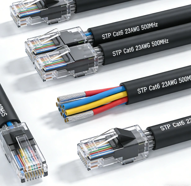
🔬 How Shielding Works: The “Invisible Armor”
A shielded cable assembly typically includes conductors, insulation, one or more shielding layers, a drain wire, and an outer jacket. The shielding layer’s job is to either reflect or absorb unwanted electromagnetic energy and safely channel it to ground.
The effectiveness of this shielding is measured in decibels (dB) and depends on several factors:
- Material conductivity and permeabilityof the shield.
- Shielding coverage and layer count(e.g., braid, foil, or a combination).
- The quality of the shield-to-connector termination.
- Proper grounding practices.
For instance, a braided copper shield offers excellent low-frequency performance and flexibility, while a foil shield provides near-100% coverage for high frequencies. Many high-performance industrial cables use a hybrid shielding structure(foil plus braid) to achieve optimal performance across a wide frequency range.
📊 Braided vs. Foil vs. Hybrid Shielding: 2026 Selection Guide
Choosing the right shielding type is a critical decision that impacts EMI performance, flexibility, cost, and manufacturability. Here’s a comparison based on 2026 industrial practices:
| Shielding Type | Typical Shielding Effectiveness | Key Strengths | Limitations | Best Applications |
|---|---|---|---|---|
| Braided Shield | 70–95% coverage | Excellent low-frequency EMI protection, superior mechanical strength, long flex life. | Gaps in coverage, heavier than foil. | Industrial robots, power cables, machinery with high vibration. |
| Foil Shield | ~100% coverage | Superior high-frequency EMI/RFI suppression, lightweight, cost-effective for high-volume runs. | Poor flex life, less effective at low frequencies. | Data cables, control cables in static installations, telecom. |
| Hybrid (Foil+Braid) | Up to 15–25 dB higher than single-layer | Combines high-frequency coverage of foil with mechanical durability of braid. | More complex to manufacture and terminate. | High-speed industrial Ethernet, servo motor cables, EV charging. |
🚀 The 2026 Game-Changer: Graphene-Enhanced Shielding
While traditional shielding materials like copper and aluminum remain foundational, graphene is emerging as a breakthrough additivefor next-generation industrial cables.
What is Graphene-Enhanced Shielding?
Graphene, a single layer of carbon atoms, boasts exceptional electrical conductivity, thermal conductivity, and mechanical strength. In cable design, it’s being integrated in two main ways:
- As a Conductive Filler:Nano-composite graphene is added to semi-conductive shielding layers in power cables. This improves conductivity, thermal stability, and breakdown strength, leading to more reliable high-voltage insulation.
- As a Noise-Reducing Layer:A thin graphene coating is applied to individual twisted pairs (e.g., in medical cables). This layer reduces triboelectric noise (cable-generated interference), significantly improving signal clarity.
Real-World Performance Gains
- ECG/EKG Lead Wires:A 28AWG, 24-core cable with a graphene layer, aluminum foil, and braided shield demonstrated ultra-low noise, making it suitable for sensitive medical and quantum research equipment.
- Industrial Cables:Factories testing graphene-enhanced cables have reported up to a 15% improvement in shielding effectiveness, along with better thermal stability and longer flex life under high-vibration conditions.
Engineering Considerations
Despite its promise, widespread industrial adoption in 2026 faces challenges:
- Dispersion & Consistency:Ensuring a uniform dispersion of graphene in polymers is complex and requires precise process control.
- Cost & Scalability:While costs are decreasing, graphene remains more expensive than traditional carbon black. Its use is most viable in high-performance, value-driven applications.
- Long-Term Reliability:Data on 10+ year performance in harsh industrial environments is still being gathered, though early results are promising.
🏭 Key Applications for 2026
- Industrial Automation & Robotics:Cables must withstand constant flexing, high EMI, and temperature swings. Hybrid shields with optional graphene are increasingly common.
- Electric Vehicles (EVs) & Charging:High-voltage cables require robust shielding to manage EMI and ensure safety. Graphene-enhanced materials are being explored for lighter, more efficient solutions.
- Renewable Energy:Cables in solar farms and wind turbines need shielding that can handle UV, moisture, and mechanical stress over decades.
- Medical & Test Equipment:Ultra-low-noise cables with graphene layers are critical for accurate data acquisition in medical imaging and scientific research.
🤝 How to Choose the Right Shielded Industrial Cable Assemblies Factory
Selecting a manufacturing partner involves evaluating their technical depth, quality systems, and engineering support.
- Engineering & Prototyping:A true partner offers design for manufacturability (DFM) support and can build functional prototypes for testing.
- Shielding Expertise:The factory should have data on different shielding structures and experience with advanced materials like graphene.
- Quality Management:Look for certifications like ISO 9001, IATF 16949, and UL, plus rigorous in-house testing (EMI, tensile, thermal cycling, etc.).
- Customization & Scalability:The best factories can handle both small, complex runs and high-volume production with consistent quality.
- Compliance & Documentation:Ensure the factory can provide full material traceability and test reports to meet global regulatory standards.
FRS: Your Strategic Partner for Advanced Cable Assemblies
At FRS, we combine deep engineering expertise with a vertically integrated manufacturing approach to deliver high-performance shielded industrial cable assembliestailored to your most demanding applications.
Our capabilities include:
- Advanced Shielding Design:Expertise in braid, foil, and hybrid shielding, with proven performance in EMI-intensive environments.
- Next-Gen Materials:We are actively developing and testing graphene-enhanced cables to provide superior noise immunity and thermal performance for 2026 and beyond.
- Comprehensive Manufacturing:From rapid prototyping to high-volume production, our ISO-certified facilities ensure quality and reliability at every stage.
- Global Support:We serve OEMs worldwide, providing localized support and fast response times to meet your project deadlines.
Whether you’re designing a new robotic system, upgrading to Industry 4.0, or developing the next generation of EVs, FRS is your partner for shielded cable assemblies that perform when it matters most.
Contact our engineering team today to discuss your project requirements and discover how FRS can help you achieve a 15% or greater performance boost.
Contact Us Right Now:
TEL&WECHAT: +86-1881-875-005 (Wechat)
E-MAIL: sales@custom-cable-assemblies.com
industrial cable installation services
In the complex infrastructure of industrial facilities, the role of industrial cable installation services cannot be overstated. These services form the backbone of reliable power distribution, data transmission, and communication within manufacturing plants, refineries, warehouses, and other industrial settings. A well-executed cable installation ensures seamless operations, minimizes downtime, and mitigates risks such as electrical hazards and equipment failure. For businesses, investing in professional industrial cable installation is not just a matter of compliance with safety standards but also a strategic move to enhance operational efficiency and long-term productivity.
Key Steps in Professional Industrial Cable Installation
Professional industrial cable installation follows a systematic process to guarantee quality and performance. The first step is site assessment and planning. Technicians conduct a thorough inspection of the industrial facility to understand the layout, power requirements, environmental conditions (such as temperature, humidity, and exposure to chemicals or mechanical stress), and compliance regulations. This assessment helps in determining the type, size, and routing of cables, as well as identifying potential obstacles or safety concerns.
The second step involves cable selection. Industrial cables come in various types, including power cables, control cables, instrumentation cables, and fiber optic cables, each designed for specific applications. Factors like current capacity, voltage rating, resistance to abrasion, and environmental durability are considered when choosing the right cables. For example, in high-temperature environments, heat-resistant cables with specialized insulation are selected to prevent degradation.
Next is the installation phase, which includes cable routing, pulling, and termination. Technicians use specialized tools and equipment to route cables through conduits, trays, or trenches, ensuring minimal bending and tension to avoid signal loss or cable damage. Proper termination is crucial to establish secure connections between cables and equipment, as loose or faulty terminations can lead to arcing, overheating, or data interference. After installation, a series of testing and verification procedures are conducted, such as insulation resistance testing, continuity testing, and performance testing, to confirm that the cables meet industry standards and operational requirements.
The final step is documentation and maintenance support. Professional service providers maintain detailed records of the cable installation, including cable layouts, termination points, and test results. This documentation is invaluable for future maintenance, troubleshooting, and upgrades. Additionally, they may offer ongoing maintenance services, such as regular inspections and cable condition monitoring, to ensure the longevity and reliability of the installation.
Why Choose Professional Industrial Cable Installation Services?
Opting for professional industrial cable installation services offers numerous advantages over DIY or unqualified installations. Firstly, compliance with safety standards is guaranteed. Industrial facilities are subject to strict regulations, such as those set by the Occupational Safety and Health Administration (OSHA) and the National Electrical Code (NEC). Professional technicians are well-versed in these standards and ensure that the installation adheres to all safety guidelines, reducing the risk of electrical accidents and legal penalties.
Secondly, expertise and experience play a vital role in handling complex industrial environments. Industrial cable installation often involves working with high-voltage systems, intricate machinery, and challenging spaces. Professional teams have the knowledge and experience to navigate these complexities, ensuring that the installation is done efficiently and correctly the first time.
Thirdly, reliability and durability are key benefits. Professional installations use high-quality materials and follow best practices, resulting in cables that can withstand the harsh conditions of industrial settings. This reduces the likelihood of cable failures, which can cause costly downtime and disrupt production schedules.
FRS: Your Trusted Partner for Industrial Cable Installation
When it comes to industrial cable installation services, FRS brand factory stands out as a reliable and professional partner. With years of experience in serving diverse industrial sectors, FRS boasts a team of highly skilled technicians who are trained in the latest installation techniques and safety standards. We prioritize quality at every step, from site assessment to final testing, using premium-grade cables and state-of-the-art equipment to ensure optimal performance.
FRS understands the unique needs of industrial businesses and offers customized installation solutions tailored to specific operational requirements. Whether you need a new cable installation for a greenfield project or an upgrade for an existing facility, we are committed to delivering efficient, safe, and durable results. Our after-sales support, including maintenance and troubleshooting services, ensures that your industrial cables continue to perform at their best for years to come. Choose FRS for industrial cable installation services that you can rely on to keep your operations running smoothly.
Study Exposes Hidden Costs of Cable Waste
The Invisible Crisis
While most consumers worry about plastic bottles and food packaging, discarded cables quietly become one of fastest-growing waste streams. A 2025 Global E-Waste Monitor report reveals that cable waste increased by 28% since 2020, with less than 20% being properly recycled.
Three Major Hidden Costs
- Resource Drain
- Copper mining for new cables consumes 85% more energy than recycling existing ones
- Each kilometer of discarded LAN cables contains ~25kg of reusable copper
- Environmental Impact
- PVC insulation takes 500+ years to decompose
- Burnt cables release toxic dioxins – 1kg cable waste pollutes 5m³ of soil
- Economic Loss
- $3.2 billion in recoverable metals landfilled annually
- Recycling creates 6x more jobs than landfilling
What You Can Do Today
- Repair before replacement (60% of discarded cables still functional)
- Recycle at certified e-waste facilities (check R2 or e-Stewards listings)
- Choose cables with recyclable labeling (look for TCO Certified or EPEAT badges)
The Silver Lining
New “cable buyback” programs now pay $0.50-$2/kg for old cables. Tech giants like Apple and Dell offer mail-in recycling with store credits. Municipalities in 14 countries provide free cable collection bins at electronics retailers.
“When we throw away cables, we’re literally burying money and poisoning our future,” warns Dr. Elena Torres, lead researcher of the MIT Waste Analytics Lab. “Smart handling of this waste could power 3 million homes annually through recovered materials.”
Industries That Commonly Use Cable Assemblies1
1.Telecommunications
Cable assemblies ensure high-speed data transfer and connectivity in:
Fiber optic networks: LC/SC/ST connectors and splice closures for telecom towers and data centers13.
5G infrastructure: RF coaxial cables and shielded assemblies for base stations and antennas4.
2. Industrial Automation
Used extensively in automated systems for:
Robotic arms: Flexible M12/M8 connectors and PUR-jacketed cables resistant to oil and abrasion14.
Control panels: D-Sub and RJ45 connectors for PLCs and sensor networks13.
3. Aerospace and Defense
High-reliability assemblies for:
Aircraft systems: MIL-SPEC circular connectors and PTFE-insulated cables for extreme temperatures14.
Military communications: EMI-shielded coaxial cables and ruggedized terminal blocks34.
4. Energy and Power
Critical in energy generation and distribution:
Renewable energy: UV-resistant LSZH-jacketed cables for solar farms and offshore wind turbines27.
High-voltage grids: XLPE-insulated power cables and armored joints for underground transmission27.
5. Automotive and Transportation
Essential for vehicle electrification and safety:
Electric vehicles (EVs): High-voltage connectors and shielded harnesses for battery management47.
Railways and ships: Fire-retardant LSZH assemblies for subways and marine environments23.
6. Healthcare and Medical Devices
Precision assemblies for:
Diagnostic equipment: Medical-grade TPE-jacketed cables for MRI machines and patient monitors56.
Surgical tools: Sterilizable fiber optic bundles for minimally invasive procedures46.
7. Broadcasting and Consumer Electronics
Supporting media and consumer tech:
Broadcast studios: Coaxial cables with EMI shielding for HD video and audio transmission34.
Smart devices: Micro-USB and HDMI assemblies for consumer electronics
EV Boom Ignites Cable Innovations: Powering the Future of Electric Mobility
The rapid growth of the electric vehicle (EV) industry is driving unprecedented advancements in cable technology. As automakers and charging infrastructure providers race to meet global demand, innovative cable designs and materials are emerging to address critical challenges in power delivery, safety, and sustainability. Here’s how the EV revolution is reshaping cable engineering.
1. High-Voltage Demands Push Cable Engineering Forward
Modern EVs require cables capable of handling higher voltages (up to 800V or more) to enable faster charging and longer ranges. Traditional copper cables, while conductive, face limitations in heat dissipation and weight. Engineers are now developing:
- Lightweight Aluminum Alloys: Reducing cable weight by up to 50% compared to copper, improving vehicle efficiency.
- Advanced Insulation Materials: Thermally resistant polymers like cross-linked polyethylene (XLPE) prevent overheating during ultra-fast DC charging.
- Compact Shielding: Multi-layer shielding minimizes electromagnetic interference (EMI), ensuring safe operation alongside onboard electronics.
2. Liquid-Cooled Charging Cables: A Game-Changer for Fast Charging
To support 350 kW+ charging stations, liquid-cooled cables have emerged as a breakthrough. These cables integrate cooling channels within their design, circulating a non-conductive fluid to manage extreme temperatures generated during rapid power transfer. Benefits include:
- Sustained high-power charging without degradation.
- Thinner, more flexible designs for easier handling.
- Extended lifespan in extreme climates.
Companies like Tesla and ChargePoint are already deploying liquid-cooled systems in next-gen Superchargers and public networks.
3. Sustainability-Driven Material Innovations
The EV industry’s focus on sustainability extends to cable production. Key developments include:
- Recyclable Thermoplastics: Replacing conventional PVC with eco-friendly materials that retain durability.
- Bio-Based Insulation: Plant-derived polymers reduce reliance on fossil fuels.
- Closed-Loop Manufacturing: Recycling copper and aluminum scrap during production cuts waste by 30%.
These innovations align with global regulations like the EU’s Circular Economy Action Plan.
4. Smart Cables with Embedded Diagnostics
Next-gen EV cables are becoming “smarter.” Integrated sensors and IoT-enabled connectors can:
- Monitor real-time temperature, voltage, and wear.
- Alert users to potential faults before they escalate.
- Sync data with vehicle software for predictive maintenance.
Such features enhance safety and reduce downtime, critical for commercial fleets and autonomous EVs.
5. Standardization Efforts Accelerate Adoption
Organizations like ISO, IEC, and SAE are updating standards to harmonize cable designs globally. Key focus areas include:
- Universal Connector Compatibility: Ensuring interoperability across CCS, NACS, and CHAdeMO systems.
- Safety Protocols: Certifying flame-retardant materials for battery-to-cable interfaces.
- High-Power Testing: Validating performance under 500A+ loads.
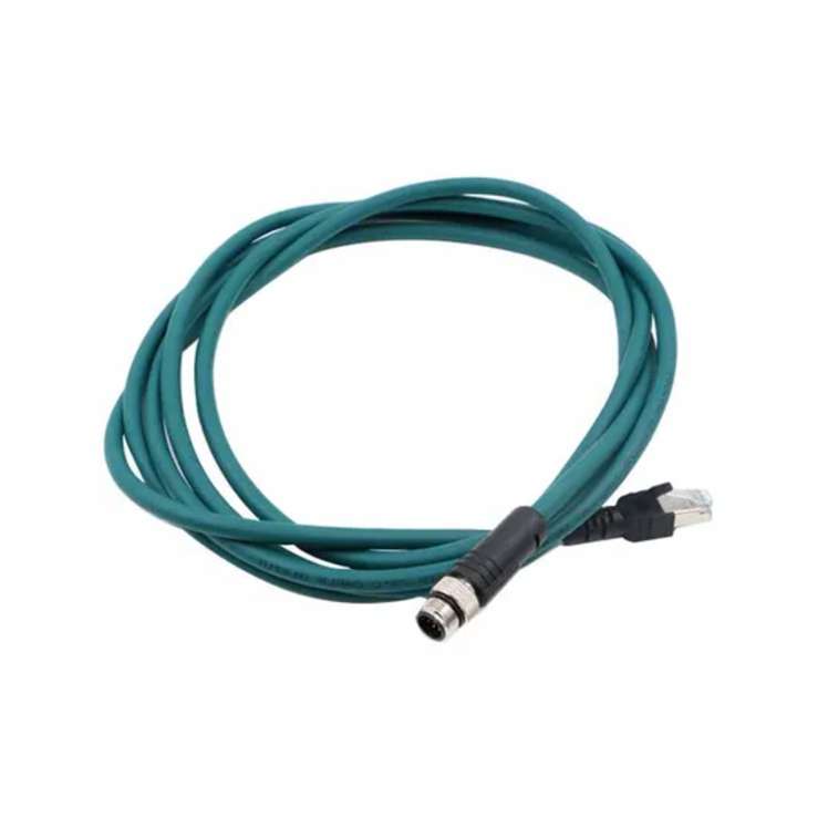
Industrial Cable Connectors: The Backbone of Reliable Industrial Operations
In the complex and demanding landscape of industrial operations, every component plays a critical role in ensuring seamless functionality, safety, and efficiency. Among these essential components, industrial cable connectors stand out as the unsung heroes that facilitate the transfer of power, data, and signals between various machinery, equipment, and systems. Without high-quality, reliable industrial cable connectors, even the most advanced industrial setups would falter, leading to costly downtime, reduced productivity, and potential safety hazards. This article delves into the world of industrial cable connectors, exploring their importance, types, key considerations for selection, installation best practices, maintenance tips, and future trends, providing a comprehensive guide for businesses and professionals seeking to optimize their industrial operations.
The Critical Importance of Industrial Cable Connectors in Industrial Settings
Industrial environments are characterized by harsh conditions such as extreme temperatures, moisture, dust, vibration, chemical exposure, and mechanical stress. In such settings, the performance and durability of industrial cable connectors are paramount. These connectors serve as the interface points that ensure a secure and stable connection between cables, which are responsible for transmitting vital power and data. A single faulty connector can disrupt the entire workflow, resulting in production halts that can cost businesses thousands of dollars per hour. For example, in a manufacturing plant, a damaged power connector could stop an assembly line, leading to missed deadlines and lost orders. In the energy sector, a faulty data connector in a power grid monitoring system could compromise the ability to detect and respond to potential outages, posing risks to public safety.
Moreover, industrial cable connectors play a crucial role in ensuring safety. They are designed to prevent electrical shocks, short circuits, and other electrical hazards that can occur in industrial environments. High-quality connectors are built with insulation materials that can withstand high voltages and temperatures, reducing the risk of electrical fires and accidents. Additionally, they provide protection against environmental contaminants such as water and dust, which can corrode electrical components and cause malfunctions. In industries such as oil and gas, where explosive atmospheres are a constant threat, specialized industrial cable connectors with explosion-proof ratings are essential to prevent ignition sources and ensure the safety of workers and equipment.
Common Types of Industrial Cable Connectors and Their Applications
Industrial cable connectors come in a wide variety of types, each designed to meet specific application requirements. Understanding the different types and their uses is crucial for selecting the right connector for a particular industrial setup. Below are some of the most common types of industrial cable connectors:
1. Circular Connectors
Circular connectors are one of the most widely used types of industrial cable connectors due to their robust design and versatility. They feature a circular shape that provides a secure, twist-lock connection, making them resistant to vibration and accidental disconnection. Circular connectors are available in various sizes, pin configurations, and materials, making them suitable for a range of applications. They are commonly used in machinery, robotics, aerospace, and defense industries. For instance, in robotics, circular connectors are used to connect motors, sensors, and controllers, ensuring reliable communication and power transfer between components. In aerospace applications, they are designed to withstand extreme temperatures, high pressures, and harsh environmental conditions.
2. Rectangular Connectors
Rectangular connectors are ideal for applications where space is limited, as their compact design allows for high-density packaging of pins. They are often used in industrial control systems, automation equipment, and data communication systems. Rectangular connectors feature a modular design, which allows for easy customization by adding or removing pins and modules. This flexibility makes them suitable for a wide range of applications, from simple signal transmission to complex power distribution. In industrial control panels, rectangular connectors are used to connect various control devices such as PLCs (Programmable Logic Controllers), HMIs (Human-Machine Interfaces), and sensors, providing a neat and organized connection solution.
3. Power Connectors
Power connectors are specifically designed to transmit high levels of electrical power. They are built with large contact surfaces and robust insulation materials to handle high currents and voltages. Power connectors are available in various types, including AC power connectors, DC power connectors, and high-power connectors for industrial machinery. They are commonly used in manufacturing plants, power generation facilities, and heavy equipment. For example, in a steel mill, high-power connectors are used to connect large motors and heating elements, ensuring a stable and efficient power supply. Power connectors are also designed with safety features such as locking mechanisms and insulation barriers to prevent electrical accidents.
4. Data Connectors
With the rise of Industry 4.0 and the increasing demand for data-driven industrial operations, data connectors have become essential components. These connectors are designed to transmit high-speed data signals between various devices such as sensors, cameras, and computers. Common types of data connectors used in industrial settings include Ethernet connectors (such as RJ45), USB connectors, and fiber optic connectors. Ethernet connectors are widely used in industrial networks to connect devices to the internet and local area networks (LANs), enabling real-time data transfer and remote monitoring. Fiber optic connectors, on the other hand, are used for high-speed, long-distance data transmission, as they offer low signal loss and immunity to electromagnetic interference (EMI).
5. Waterproof and Dustproof Connectors
In industrial environments where moisture, dust, and other contaminants are present, waterproof and dustproof connectors are essential. These connectors are rated according to the IP (Ingress Protection) standard, which indicates their level of protection against solid objects and liquids. For example, a connector with an IP67 rating is completely dust-tight and can withstand immersion in water up to 1 meter for 30 minutes. Waterproof and dustproof connectors are commonly used in outdoor applications, food and beverage processing plants, and wastewater treatment facilities. In the food and beverage industry, these connectors are used to connect equipment in washdown areas, where they are regularly exposed to water and cleaning chemicals.
Key Considerations for Selecting Industrial Cable Connectors
Selecting the right industrial cable connector is a critical decision that can impact the performance, reliability, and safety of an industrial system. There are several key factors that businesses and professionals should consider when choosing industrial cable connectors:
1. Environmental Conditions
The first and foremost consideration is the environmental conditions in which the connector will be used. Factors such as temperature range, humidity, exposure to dust, water, chemicals, and vibration must be taken into account. For example, if the connector will be used in a high-temperature environment such as a foundry, it should be made of materials that can withstand extreme heat. If it will be used in a wet environment such as a marine application, a waterproof connector with a high IP rating is essential.
2. Electrical Requirements
The electrical requirements of the application, including voltage, current, and signal type, are also important factors. Power connectors must be able to handle the maximum current and voltage of the system, while data connectors must support the required data transfer rate. It is crucial to select a connector that can meet or exceed the electrical specifications of the application to avoid overheating, signal loss, or electrical failures.
3. Mechanical Requirements
Mechanical requirements such as the number of pins, pin configuration, and mating style should also be considered. The connector must have the correct number of pins to accommodate all the cables and signals that need to be transmitted. The pin configuration should be compatible with the equipment and cables being used. Additionally, the mating style (such as twist-lock, push-pull, or bayonet) should be easy to use and provide a secure connection that is resistant to accidental disconnection.
4. Material Quality
The quality of the materials used in the connector is another important consideration. High-quality materials such as brass, stainless steel, and thermoplastics are commonly used in industrial cable connectors due to their durability, corrosion resistance, and mechanical strength. The contacts of the connector should be made of materials with good electrical conductivity, such as copper or gold-plated copper, to ensure low contact resistance and reliable signal transmission.
5. Safety Standards and Certifications
Industrial cable connectors must comply with relevant safety standards and certifications to ensure their safety and performance. For example, in the United States, connectors may need to be UL (Underwriters Laboratories) listed, while in Europe, they may need to be CE (Conformité Européenne) marked. Additionally, connectors used in hazardous environments may need to meet explosion-proof standards such as ATEX or IECEx.
Installation Best Practices for Industrial Cable Connectors
Proper installation of industrial cable connectors is essential to ensure their performance and reliability. Poor installation can lead to loose connections, signal loss, electrical hazards, and premature failure of the connector. Below are some best practices for installing industrial cable connectors:
1. Prepare the Cables
Before installing the connector, it is important to properly prepare the cables. This includes stripping the cable insulation to the correct length, ensuring that the conductors are clean and free of damage, and twisting the conductors (if necessary) to prevent fraying. It is also important to use the correct tools for stripping and preparing the cables to avoid damaging the conductors.
2. Follow the Manufacturer’s Instructions
Each type of industrial cable connector has specific installation instructions provided by the manufacturer. It is crucial to follow these instructions carefully to ensure proper installation. The instructions may include details on how to assemble the connector, how to terminate the cables, and how to mate the connector with the equipment.
3. Ensure a Secure Connection
The connector should be mated securely to the equipment to prevent accidental disconnection. This may involve using locking mechanisms such as twist-locks, screws, or clips. It is important to check that the connector is fully seated and locked in place before powering on the system.
4. Protect Against Environmental Contaminants
If the connector is being installed in a harsh environment, additional protection may be required. This can include using cable glands to seal the entry point of the cable into the connector, applying waterproof tape or sealant around the connector, or installing the connector in a protective enclosure.
5. Test the Connection
After installation, it is important to test the connection to ensure that it is working properly. This can include checking for continuity, measuring the voltage and current, and testing the data transfer rate (for data connectors). Any issues found during testing should be addressed immediately to avoid problems in the future.
Maintenance Tips for Industrial Cable Connectors
Regular maintenance of industrial cable connectors is essential to extend their lifespan and ensure their continued performance. Below are some maintenance tips for industrial cable connectors:
1. Inspect Regularly
Connectors should be inspected regularly for signs of damage, wear, or corrosion. This includes checking the contacts for discoloration or oxidation, the insulation for cracks or tears, and the locking mechanisms for proper operation. Inspections should be performed at least once a month, or more frequently in harsh environments.
2. Clean the Connectors
Dust, dirt, and other contaminants can accumulate on the connectors over time, leading to poor contact and signal loss. Connectors should be cleaned regularly using a soft brush or compressed air to remove any debris. For connectors with corrosion, a mild cleaning solution (such as isopropyl alcohol) can be used to clean the contacts, but it is important to follow the manufacturer’s instructions to avoid damaging the connector.
3. Tighten Loose Connections
Vibration and thermal expansion can cause connections to become loose over time. It is important to check the connectors regularly and tighten any loose screws or locking mechanisms to ensure a secure connection.
4. Replace Damaged Connectors
If a connector is damaged, worn, or corroded beyond repair, it should be replaced immediately. Using a damaged connector can lead to electrical hazards, signal loss, and equipment failure. It is important to use a replacement connector that is compatible with the original connector and meets the same electrical and environmental specifications.
Future Trends in Industrial Cable Connectors
The industrial cable connector industry is constantly evolving to meet the changing needs of industrial operations. Some of the key future trends in industrial cable connectors include:
1. Miniaturization
As industrial equipment becomes more compact and densely packed, there is a growing demand for miniaturized industrial cable connectors. These connectors are smaller in size but still offer the same level of performance and reliability as larger connectors. Miniaturized connectors are ideal for applications such as robotics, medical devices, and portable equipment.
2. High-Speed Data Transmission
With the increasing adoption of Industry 4.0 and the Internet of Things (IoT), there is a growing need for industrial cable connectors that can support high-speed data transmission. Connectors with speeds of up to 100 Gbps or more are being developed to meet the demands of real-time data processing and analytics.
3. Smart Connectors
Smart connectors are equipped with sensors and electronics that can monitor the performance of the connector and the system. These connectors can provide real-time data on parameters such as temperature, voltage, current, and signal quality, allowing for predictive maintenance and early detection of potential issues. Smart connectors are expected to become more prevalent in industrial settings in the coming years.
4. Environmental Sustainability
There is a growing focus on environmental sustainability in the industrial sector, and this trend is also affecting the industrial cable connector industry. Manufacturers are developing connectors made from recycled materials and using more environmentally friendly production processes. Additionally, connectors are being designed to be more energy-efficient, reducing power consumption and carbon emissions.
Why Choose FRS for Your Industrial Cable Connector Needs
When it comes to industrial cable connectors, FRS is a trusted brand that delivers high-quality, reliable, and innovative solutions tailored to meet the diverse needs of industrial operations. With years of experience in the industry, FRS has established itself as a leading manufacturer of industrial cable connectors, offering a wide range of products including circular connectors, rectangular connectors, power connectors, data connectors, and waterproof and dustproof connectors.
At FRS, we understand the importance of industrial cable connectors in ensuring the smooth and safe operation of your equipment and systems. That’s why we use only the highest quality materials and advanced manufacturing processes to produce our connectors. Our products are rigorously tested to meet or exceed international safety standards and certifications, including UL, CE, ATEX, and IECEx, ensuring their performance and reliability in even the harshest industrial environments.
We also offer customization options to meet the specific requirements of your application. Our team of experienced engineers works closely with you to design and develop connectors that are tailored to your unique needs, whether it’s a custom pin configuration, a specialized material, or a unique environmental rating. Additionally, we provide comprehensive technical support and after-sales service, ensuring that you get the most out of your FRS connectors.
Whether you’re in the manufacturing, energy, aerospace, defense, or any other industrial sector, FRS has the perfect industrial cable connector solution for you. Choose FRS for reliable, high-performance industrial cable connectors that keep your operations running smoothly and safely. Contact us today to learn more about our products and services.
Coaxial Cable with Gold-Plated Contacts for Better Conductivity
In the ever – evolving landscape of electronics and communication, the quality of cables used for signal transmission plays a pivotal role. Among these, coaxial cables with gold – plated contacts have emerged as a top choice for those seeking superior performance.
Understanding Coaxial Cables
Coaxial cables are designed with a unique structure that enables efficient signal transmission. They consist of a central conductor, which is typically made of copper. This central conductor is surrounded by an insulating layer, often made of materials like polyethylene. Beyond the insulator, there is an outer conductor, usually in the form of a braided metal shield or a metallic foil. This outer conductor serves as a shield against electromagnetic interference (EMI) and radio – frequency interference (RFI). Finally, the entire cable is encased in a protective outer jacket, which can be made of PVC or other durable materials.
The Significance of Gold – Plated Contacts
Exceptional Conductivity
Gold is renowned for its excellent electrical conductivity. It has a very low resistivity, which means that when used as a plating on the contacts of a coaxial cable, it significantly reduces the resistance to the flow of electrical current. In signal transmission, lower resistance translates to less energy loss as the signal travels through the cable. This is particularly crucial for high – frequency signals, such as those used in digital audio and video applications, where even the slightest loss can lead to a degradation in quality. For example, in a home theater system, a coaxial cable with gold – plated contacts can ensure that the digital audio signal from a Blu – ray player to an amplifier is transmitted with minimal loss, resulting in a more accurate and immersive sound experience.
Superior Corrosion Resistance
One of the major challenges in maintaining the integrity of cable connections is corrosion. Connectors are often exposed to various environmental factors, including moisture, humidity, and even chemical pollutants. Gold is highly resistant to corrosion. When the contacts of a coaxial cable are gold – plated, they are protected from oxidation and other forms of corrosion. This not only extends the lifespan of the cable but also ensures that the signal quality remains consistent over time. In outdoor applications, such as satellite dish installations, where the cables are constantly exposed to the elements, coaxial cables with gold – plated contacts are far more reliable compared to those with non – gold – plated contacts.
Enhanced Durability
Gold – plated contacts are also more durable in terms of wear and tear. During the process of plugging and unplugging the cable, the contacts are subjected to friction. The hardness and smoothness of the gold plating help to reduce this friction, preventing the contacts from getting scratched or damaged. This means that the cable can be used for a greater number of connection – disconnection cycles without experiencing a decline in performance. In professional audio – visual setups, where cables are frequently connected and disconnected for equipment changes or maintenance, the durability of gold – plated contacts is a highly desirable feature.
Applications of Coaxial Cables with Gold – Plated Contacts
Home Entertainment Systems
In modern home entertainment setups, coaxial cables with gold – plated contacts are widely used. They are essential for connecting devices such as high – definition televisions (HDTVs), Blu – ray players, game consoles, and audio receivers. For instance, when connecting a satellite receiver to an HDTV, a coaxial cable with gold – plated contacts can ensure a stable and high – quality signal transmission, delivering sharp images and clear sound. In multi – room audio systems, these cables can also be used to distribute digital audio signals, allowing for a seamless audio experience throughout the house.
Professional Audio and Video Production
In the world of professional audio and video production, the quality of signal transmission is non – negotiable. Coaxial cables with gold – plated contacts are used in studios for connecting audio mixers, video cameras, recorders, and monitors. In a recording studio, for example, a coaxial cable with gold – plated contacts can be used to transfer the high – quality audio signal from a microphone pre – amplifier to a digital audio workstation. This ensures that the nuances in the sound, such as the subtle timbre of an instrument or the clarity of a singer’s voice, are accurately captured and transmitted without any loss or interference.
Telecommunications and Networking
Telecommunications companies rely on coaxial cables for various applications. In cable television networks, these cables are used to transmit signals from the service provider’s headend to the subscriber’s home. The gold – plated contacts help in maintaining a strong and stable signal, reducing the occurrence of signal dropouts or pixelation. In local area networks (LANs), coaxial cables with gold – plated contacts can be used for short – distance connections between network devices, such as routers, switches, and computers. They can provide a reliable and fast connection, especially in environments where there is a significant amount of electromagnetic interference.
Choosing the Right Coaxial Cable with Gold – Plated Contacts
Consider the Gauge
The gauge of a coaxial cable refers to the thickness of the central conductor. A lower gauge number indicates a thicker conductor. Thicker conductors generally have lower resistance and can carry higher – power signals over longer distances without significant loss. For applications where the cable needs to cover a long distance, such as in a large – scale security camera installation, a coaxial cable with a lower gauge and gold – plated contacts would be a suitable choice.
Look at the Shielding
The shielding of a coaxial cable is crucial for protecting the signal from external interference. There are different types of shielding, including single – layer shielding, double – layer shielding, and triple – layer shielding. Triple – layer shielding, which often consists of a combination of aluminum foil, braided copper, and another layer of shielding material, provides the highest level of protection against EMI and RFI. In environments with a high amount of electromagnetic noise, such as near industrial equipment or in urban areas with a lot of wireless signals, a coaxial cable with triple – layer shielding and gold – plated contacts is recommended.
Check the Connector Type
Coaxial cables come with various connector types, such as BNC (Bayonet Neill – Concelman), RCA (Radio Corporation of America), and F – type connectors. The choice of connector depends on the devices that the cable will be connecting. For example, BNC connectors are commonly used in professional video applications, while RCA connectors are more prevalent in home audio and video setups. Ensure that the coaxial cable you choose has the appropriate connector type with gold – plated contacts for a secure and high – quality connection.
In conclusion, coaxial cables with gold – plated contacts offer a host of benefits in terms of conductivity, corrosion resistance, and durability. They are suitable for a wide range of applications, from home entertainment to professional audio – visual production and telecommunications. By understanding the key factors to consider when choosing these cables, consumers and professionals alike can make an informed decision and enjoy the advantages of superior signal transmission.
Which Insulation Materials Are Best for High Temperature Industrial Cable Assemblies?
Selecting the correct insulation for high-temperature industrial cable assemblies is critical for safety, reliability, and longevity. A wrong choice can lead to premature failure, downtime, and even hazardous situations. This guide provides a detailed, practical comparison to help engineers, procurement managers, and project specifiers make an informed decision.
Understanding the Operating Environment
Before comparing materials, define your application’s specific demands:
- Continuous Operating Temperature:The sustained temperature the cable will face.
- Short-Term/Peak Temperature:Temperatures during process upsets or startup/shutdown cycles.
- Chemical Exposure:Oils, solvents, acids, alkalis, or steam.
- Mechanical Stress:Abrasion, flexing, vibration, or impact.
- Electrical Requirements:Voltage rating, dielectric strength, and signal integrity needs.
- Compliance & Standards:Industry-specific requirements (e.g., UL, IEC, Mil-Spec, IEEE).
Top High-Temperature Insulation Materials: A Detailed Comparison
Here’s a breakdown of the most common and effective materials for high-temperature industrial applications.
1. Silicone Rubber
- Temperature Range:-60°C to +180°C (continuous), up to +200°C for some grades.
- Key Strengths:Excellent flexibility, even at low temperatures. Good moisture and UV resistance. Inherently flame-retardant.
- Weaknesses:Poor abrasion and cut-through resistance. Can be easily damaged if not protected by a suitable jacket or conduit.
- Best For:Internal wiring in control panels near ovens, lighting systems in high-heat areas, and applications requiring frequent flexing.
- Practical Tip:Always use a braided fiberglass or textile sleeve over silicone-insulated wires in high-abrasion environments.
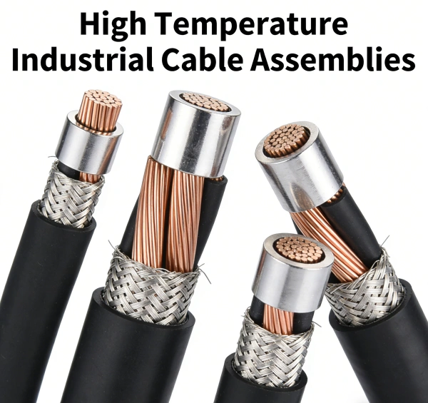
2. ETFE (Ethylene Tetrafluoroethylene)
- Temperature Range:-100°C to +150°C (continuous).
- Key Strengths:Exceptional mechanical toughness—high tensile strength and abrasion resistance. Good chemical and radiation resistance. Lighter weight than many other fluoropolymers.
- Weaknesses:Lower continuous temperature rating compared to PTFE or PFA.
- Best For:Aerospace and military harnesses, robotics cables, and industrial automation where both heat and physical abuse are concerns.
3. FEP (Fluorinated Ethylene Propylene)
- Temperature Range:-65°C to +200°C (continuous).
- Key Strengths:Excellent chemical resistance. Melt-processable, allowing for extrusion over multi-conductor cables. Lower smoke and toxicity when burned compared to some materials.
- Weaknesses:Softer than PTFE, making it more susceptible to cold flow (deformation under pressure).
- Best For:Plenum cable in data centers, chemical plant wiring, and applications requiring good flexibility and chemical inertness.
4. PTFE (Polytetrafluoroethylene / Teflon®)
- Temperature Range:-73°C to +204°C (continuous), with short-term peaks to +260°C.
- Key Strengths:The industry benchmark for high-temperature and chemical resistance. Extremely low dielectric constant and loss, ideal for high-frequency signal cables. Excellent anti-stick properties.
- Weaknesses:Difficult to process; requires specialized etching for bonding in potting or connectors. Can be brittle in thick sections and has poor cut-through resistance without protection.
- Best For:Aerospace, military (MIL-SPEC), down-hole oil & gas tools, and any application where ultimate chemical/heat resistance is non-negotiable.
5. PFA (Perfluoroalkoxy Alkane)
- Temperature Range:-65°C to +250°C (continuous), with peaks to +260°C.
- Key Strengths:Combines PTFE’s chemical and heat resistance with FEP’s melt-processability. Excellent for extrusion and jacketing. Superior performance in severe chemical environments.
- Weaknesses:Higher cost than PTFE and FEP.
- Best For:High-performance wire and cable for chemical processing, pharmaceutical, and semiconductor industries where purity and chemical resistance are paramount.
6. Fiberglass & Mica Composites
- Temperature Range:Up to +550°C (fiberglass), up to +1000°C or more (with mica).
- Key Strengths:Withstand extremely high temperatures. Mica provides excellent electrical insulation even when hot.
- Weaknesses:Brittle, not flexible. Primarily used as a wrap or tape, not a primary extruded insulation. Requires careful handling and often an outer protective sleeve.
- Best For:Internal wiring of industrial furnaces, kilns, and heaters. Used as a protective wrap over primary insulated conductors in extreme heat zones.
7. PEEK (Polyetheretherketone)
- Temperature Range:-60°C to +250°C (continuous).
- Key Strengths:Outstanding mechanical strength and fatigue resistance at high temperatures. Excellent chemical and hydrolysis resistance. High radiation resistance.
- Weaknesses:Very high material cost, limiting use to highly specialized applications.
- Best For:Wire for down-hole drilling, aerospace engine compartments, and medical devices requiring autoclaving.
Quick Selection Guide by Temperature Range
| Continuous Temperature | Recommended Primary Insulation | Key Consideration |
|---|---|---|
| Up to 105°C | Heat-Resistant PVC, XLPE | Cost-effective for many industrial controls. |
| 105°C to 150°C | Silicone Rubber, ETFE | Balance of flexibility and toughness. |
| 150°C to 200°C | Silicone (high-temp grade), FEP | Consider chemical exposure. |
| 200°C to 260°C | PTFE, PFA | The standard for extreme heat and chemicals. |
| Above 260°C | Fiberglass/Mica wrapsover PTFE/PFA | Use as a protective layer; not a standalone insulation. |
Critical Considerations & Common Pitfalls
- Don’t Mix Materials Blindly:Using different insulation types in close proximity can lead to galvanic corrosion or compatibility issues, especially in high-heat, high-humidity environments. Consult with your cable manufacturer.
- Voltage Derating is Essential:High temperatures reduce a cable’s voltage rating. Alwaysconsult the manufacturer’s derating curves. A cable rated for 600V at 20°C may only be safe for 300V at 200°C.
- Beware of “Cheap” High-Temp Cable:Substandard materials may meet the temperature spec initially but fail rapidly due to poor aging characteristics. Verify supplier certifications and request material datasheets.
- Consider the Entire Assembly:The insulation is only one part. Ensure connectors, potting compounds, and marking sleeves are also rated for the same high-temperature environment. A weak link anywhere can cause failure.
- Mechanical Protection is Key:For PTFE and silicone, which have poor abrasion resistance, always specify an additional protective layer like a fiberglass or stainless steel braid, especially in high-vibration or abrasive environments.
Actionable Recommendations for Your Next Project
- For General Industrial Ovens/Heaters (150-200°C):Start with silicone rubberinsulated wire, but always specify an overall fiberglass braidfor mechanical protection. Verify oil and chemical resistance if needed.
- For Chemical Processing Plants (200°C+):PFAis often the best choice, offering the best balance of extreme temperature, broad chemical resistance, and processability. Use PTFEif the application is less mechanically demanding.
- For Aerospace, Military, or Down-hole Tools:PTFEis the baseline. For areas with extreme mechanical stress (e.g., engine bays), consider ETFEfor its toughness or PEEKfor ultimate performance, if the budget allows.
- For Furnace & Kiln Internal Wiring:Use a multi-conductor cable with PTFE-insulated conductors, an overall fiberglass or mica tape wrap, and a stainless steel braidfor protection.
Professional Summary
Choosing the best high-temperature insulation material is a balance of thermal performance, chemical resistance, mechanical durability, and cost. For temperatures up to 200°C, silicone rubber(with protection) and FEPare strong candidates. For the most demanding applications exceeding 200°C, especially with chemical exposure, PTFEand PFAare the industry standards. Always verify material compatibility, apply appropriate voltage derating, and protect softer insulations from mechanical damage. By carefully matching the material properties to your specific operating environment using the guidelines above, you can ensure the safety, reliability, and longevity of your high-temperature cable assemblies, minimizing costly downtime and failure risks.
Real-Time Monitoring: Your Shield Against Costly Cable Failures
Cable systems are the vital circulatory network delivering power and data that keeps our modern world running. Yet, they operate largely out of sight and, too often, out of mind – until disaster strikes. A single cable failure can cripple operations, incur staggering costs (running into the hundreds of thousands or even millions for unplanned downtime and repairs), compromise safety, and damage reputations. The good news? Advanced real-time monitoring for cable diagnostics has emerged as a powerful, proactive defense, transforming how we manage critical infrastructure. By continuously watching the health of cables, we move from reactive firefighting to intelligent, cable failure prevention.
Why Cable Failures Are More Than Just an Inconvenience
- Massive Financial Loss: Unplanned outages halt production, delay services, and trigger expensive emergency repairs and potential contractual penalties.
- Safety Hazards: Electrical cable faults can lead to fires, explosions, and electrocution risks, endangering personnel and the public.
- Operational Disruption: Data communication loss halts networks, impacting everything from financial transactions to emergency services connectivity.
- Asset Damage: A single fault can cascade, damaging connected equipment like transformers, switchgear, or sensitive electronics.
- Reputational Damage: Frequent failures erode customer trust and confidence in utilities, industrial operators, and communication providers.
Traditional periodic inspections and reactive maintenance are simply no longer sufficient. These methods provide only snapshots in time, potentially missing critical developing faults between checks. Predictive maintenance for cable health powered by real-time data is the necessary evolution.
How Real-Time Cable Monitoring Works: The Digital Guardian
Imagine having a vigilant, digital sentry constantly tracking the pulse and temperature of every critical cable circuit. Modern continuous cable condition assessment systems utilize sophisticated sensors and analytics to achieve this:
- Critical Parameter Monitoring:
- Partial Discharge (PD) Detection: The #1 cause of HV/MV cable insulation breakdown. Real-time PD sensors identify the characteristic electrical pulses, pinpointing insulation weaknesses long before failure. Early electrical fault detection is key.
- Distributed Temperature Sensing (DTS): Fiber optic cables act as continuous linear thermometers. DTS pinpoints hotspots indicating overloading, poor ventilation, impending joint failures, or external heat sources with meter-level accuracy.
- Dielectric Loss / Tan Delta Monitoring: Measures insulation degradation by analyzing energy losses within the cable insulation, a crucial indicator of aging.
- Current Monitoring: Tracks load patterns, identifies unbalanced phases, and detects potential overload conditions threatening cable life.
- Voltage Monitoring: Ensures stable supply and detects transients or dips impacting cable stress.
- Acoustic Emission (AE) Sensing: Listens for the high-frequency sounds emitted by developing faults (e.g., tracking or treeing within insulation).
- Intelligent Data Processing & Alarms: Raw sensor data is processed locally or in the cloud using specialized algorithms (often incorporating AI/ML). These algorithms filter noise, identify patterns, and correlate data streams to distinguish normal fluctuations from genuine fault signatures. Systems trigger precise, prioritized alarms only for actionable events, minimizing false alerts. Real-time monitoring for cable diagnostics provides context, not just data.
- Visualization & Actionable Insights: Data is presented on intuitive dashboards accessible via web or mobile. Operators see:
- Real-time status across the network.
- Historical trends revealing gradual deterioration.
- Geographic location of hotspots or fault indicators.
- Severity levels of detected issues.

The Tangible Benefits of Proactive Monitoring: Protecting Your Bottom Line
Implementing a cable failure prevention system delivers compelling ROI:
- Slash Unplanned Downtime: Proactive intervention allows maintenance before catastrophic failure occurs. Schedule repairs during planned outages, minimizing disruption. Studies show utilities using monitoring reduce outage durations significantly.
- Optimize Maintenance Spend: Move from expensive, blanket replacement programs to highly targeted, condition-based interventions. Fix only what needs fixing, when it needs fixing, maximizing maintenance budgets. Asset health monitoring systems inform smart capital planning.
- Extend Cable Lifespan: By managing stress loads (like reducing power flow when temperatures rise) and addressing degradation early, cables last longer, deferring major replacement costs. Continuous cable condition assessment is the key to longevity.
- Enhanced Safety: Early detection of thermal runaway or severe PD reduces the risk of fires and arc-flash events, protecting people and property. Electrical fault detection becomes a safety net.
- Improved Operational Efficiency: Data-driven insights allow for optimized network loading, reduced losses, and better overall system planning.
- Regulatory & ESG Compliance: Demonstrates proactive asset management and risk mitigation to regulators. Reduces environmental impact from failure-related events and inefficient energy use. Predictive maintenance for cable health supports sustainability goals.
Applications: Where Real-Time Monitoring is Essential
- Utilities: Transmission & Distribution Networks (underground and subsea cables, substation connections).
- Industrial: Manufacturing plants, mines, oil & gas refineries (critical feeder cables, motor circuits).
- Data Centers & Telecommunications: High-density power cabling, backbone fiber links.
- Renewable Energy: Wind farms (turbine inter-array and export cables), solar farms (DC collection systems).
- Transportation: Rail electrification systems, airports, seaports.
Investing in Your Infrastructure’s Resilience
Real-time cable monitoring is no longer a luxury reserved for the most critical assets; it’s becoming a fundamental component of responsible infrastructure management. The cost of failure is simply too high. By providing continuous, actionable intelligence on cable health, these systems empower operators to shift from reactive crisis management to confident, predictive asset stewardship. Think of it as an insurance policy that not only protects your assets but actually enhances their performance and longevity.
Ready to Stop Reacting and Start Preventing?
Don’t wait for the next costly cable failure. Explore how modern real-time monitoring for cable diagnostics can safeguard your critical infrastructure, optimize your operations, and secure your bottom line. Contact us today for a personalized consultation and discover the power of proactive cable asset management. Our experts can help you assess your risk, identify critical circuits, and design a predictive maintenance strategy tailored to your needs.
2026 Industry Forecast: Robotics Industrial Cable Assemblies Demand to Grow 14.6% Annually
The global market for robotics industrial cable assembliesis entering a high-growth phase. Industry forecasts project a compound annual growth rate (CAGR) of approximately 14.6%through 2026, driven by the rapid expansion of industrial automation, electric vehicle (EV) production, and advanced robotics in sectors like logistics and healthcare.
This article provides a detailed analysis of the market size, key growth drivers, technology trends, regional dynamics, and practical guidance for selecting the right cable assemblies.
📈 Market Size & Growth Outlook
Multiple market studies confirm the robust growth trajectory of the robotics industrial cable assemblies sector:
- Robot Cable Assembly Segment: Forecast to grow from US254millionin2025toUS636 million by 2031, a CAGR of 16.5%.
- Robot Cables Market: Expected to reach US$1.2 billion by 2024with a CAGR of 9.2%from 2020–2034.
- Robot Cable Assembly Market (QYResearch): Projected to reach US$1,200.31 million by 2031with a CAGR of 3.7%.
The higher growth rate for “assemblies” reflects the increasing demand for pre-engineered, application-specific solutions that reduce integration time and risk for end-users.
🚀 Key Growth Drivers
- Accelerating Industrial Automation
- Robot Installations: Global installations reached 553,000 units in 2022, a 10% year-over-year increase, with automotive and electronics accounting for 65% of deployments.
- Cable Requirements: Each robot requires multiple high-flex cables for power, data, and signals, creating a direct link between robot adoption and cable demand.
- Electrification of Vehicles & Battery Manufacturing
- EV Production: The shift to EVs is driving demand for high-flex, high-voltage cables in robotic battery module and powertrain assembly. Tesla’s Gigafactories, for example, use cables that endure over 1,000 bending cycles dailywhile transmitting 600V+ power.
- Logistics & Warehouse Automation
- The rise of e-commerce is fueling demand for Automated Guided Vehicles (AGVs) and mobile robots. These applications require torsion-resistant and drag-chain-compatible cablescapable of withstanding millions of bending cycles in 24/7 operations.
- Medical & Surgical Robotics
- This high-value segment demands ultra-thin, sterilizable cableswith diameters under 1.5 mmfor surgical systems. The surgical robotics market is growing at a 17.2% CAGR, directly increasing demand for miniature, high-performance cabling.
- Energy & Infrastructure Robotics
- Inspection robots for offshore wind farms and oil refineries require cables that are corrosion-resistant, pressure-tolerant, and highly flexible. The offshore wind sector alone is expected to install over 234 GW globally by 2030.
- Agricultural & Service Robotics
- The agricultural robotics market is projected to reach $20.3 billion by 2027. These robots need UV-resistant, weatherproof cablesfor outdoor, long-duration operations.
🔧 Technology Trends in Robotics Industrial Cable Assemblies
- High Flexibility & Long Life
- New cables use advanced polymers and optimized conductor stranding to achieve 10 million to 50 million flex cycles, reducing downtime and extending robot service life.
- Miniaturization & High-Density Interconnects
- Driven by compact robots and semiconductor equipment, connectors now feature pitches as fine as 0.4–0.5 mm, requiring high-density cable assemblies that maintain performance in tight spaces.
- Hybrid & Composite Cables
- Combining power, data, and fiber in a single assembly reduces weight and clutter. Hybrid cables can integrate 480V power lines with 10 Gbps Ethernet, cutting total cable weight by up to 35%.
- Smart & Sensor-Integrated Cables
- Embedded sensors for temperature, vibration, and insulation resistance enable predictive maintenance, reducing unplanned downtime by 30–40%.
- Sustainability & Eco-Design
- Driven by regulations like the EU’s RoHS and CBAM, manufacturers are adopting halogen-free, recyclable, and bio-based materials, which is becoming a key purchasing criterion.
- Customization & Modularity
- 68% of robotics OEMsnow demand custom solutions. Modular, pre-assembled kits can reduce robot redeployment time by 60–70%.
🌏 Regional Dynamics
- Asia-Pacific (APAC): The dominant region, with China accounting for over 50% of global industrial robot installations. Driven by automotive, electronics, and EV manufacturing, APAC is the largest and fastest-growing market.
- Europe: Growth is fueled by Germany’s Industry 4.0initiatives and a strong automotive sector. There is a notable emphasis on sustainable, halogen-free cablescompliant with EU regulations.
- North America: Demand is driven by reshoring of manufacturingand growth in logistics automation. The market favors ruggedized, high-flex cables for harsh environments.
- Emerging Markets (India, Southeast Asia): Rapid growth is occurring in electronics and automotive manufacturing, creating demand for cost-effective, high-performance cables.
🏆 Leading Suppliers
The market is moderately concentrated, with key players including:
- Igus: A leader in high-flex cables, known for cables rated for 50 million flex cyclesand its cable management systems.
- HELUKABEL: Offers a wide range of cables for industrial robots, logistics, and energy applications.
- LEONI, Prysmian, Nexans: Large cable groups with strong robotics portfolios, providing high-performance solutions globally.
- Specialized Providers: Companies like REIKU, AndyMark, and Murrplastik focus on niche markets such as cleanrooms and collaborative robots.
✅ How to Choose the Right Robotics Industrial Cable Assembly
- Define the Application Profile: Match the cable to the robot’s motion (6-axis, SCARA, cobot), bend radius, and environmental conditions (temperature, chemicals, washdowns).
- Match Voltage & Current: Select the appropriate cable type (e.g., 300V vs. 600V) based on the robot’s power requirements. EV and heavy-duty robots often need 600V+ cables.
- Ensure Signal Integrity: For high-speed communication (Ethernet/IP, PROFINET), choose cables with shielding effectiveness above 90 dBand low attenuation.
- Prioritize Flex Life & Mechanical Durability: For continuous-motion robots, specify cables rated for at least 10 million flex cycles. Ensure the jacket material (PUR, TPU, TPE) matches the application’s abrasion and chemical resistance needs.
- Verify Certifications & Standards: Ensure compliance with CE, RoHS, UL, ISO 10218, and IEC 60204-1. For explosive environments, look for ATEX/IECExratings.
- Evaluate Total Cost of Ownership (TCO): While high-performance cables have a higher upfront cost, they reduce downtime and extend robot life, offering a lower TCO over time.
- Plan for Customization & Logistics: For complex projects, work with suppliers who offer custom design and pre-assembly servicesto streamline integration and reduce lead times.
Biodegradable Cables Tested for Eco-Use: A Sustainable Shift in Tech Infrastructure
Meta Description: Discover how biodegradable cables are revolutionizing industries with eco-friendly solutions. Learn about their benefits, applications, and future potential for reducing e-waste.
Introduction
As global demand for sustainable technology grows, biodegradable cables are emerging as a groundbreaking solution to reduce electronic waste (e-waste) and environmental harm. With industries like telecommunications, renewable energy, and consumer electronics prioritizing eco-conscious practices, biodegradable cables are now being rigorously tested for durability, performance, and environmental impact. This article explores the science behind these cables, their real-world applications, and why they could be the future of sustainable infrastructure.
What Are Biodegradable Cables?
Biodegradable cables are designed to decompose naturally under specific environmental conditions, leaving minimal ecological footprint. Unlike traditional cables made from PVC or polyethylene—which take centuries to break down—these cables use plant-based polymers, bio-plastics, or compostable materials.
Key Components:
- Bio-based polymers: Derived from renewable sources like cornstarch or sugarcane.
- Eco-friendly additives: Non-toxic flame retardants and stabilizers.
- Recyclable shielding: Aluminum or biodegradable metals instead of lead.
Testing and Certification: Ensuring Reliability
For biodegradable cables to replace conventional options, they must meet strict performance and safety standards. Recent tests by organizations like TÜV Rheinland and UL Solutions have focused on:
- Durability: Resistance to heat, moisture, and mechanical stress.
- Biodegradation rate: Breakdown timelines under industrial composting vs. natural environments.
- Toxicity: Ensuring no harmful residues during decomposition.
Case Study: In 2023, DSM Engineering Materials partnered with Dell Technologies to test biodegradable cables in data centers. Results showed comparable performance to traditional cables, with 90% decomposition within 18 months under controlled conditions.
Applications of Biodegradable Cables
From consumer gadgets to large-scale infrastructure, biodegradable cables are being adopted across sectors:
- Renewable Energy: Solar farms and wind turbines use biodegradable wiring to minimize environmental disruption.
- Telecoms: Companies like Ericsson are trialing biodegradable fiber-optic cables for 5G networks.
- Consumer Electronics: Brands like Google and Apple are integrating compostable charging cables into product roadmaps.
Benefits of Switching to Biodegradable Cables
- Reduced E-Waste: 53 million metric tons of e-waste were generated globally in 2023; biodegradable alternatives could cut landfill contributions.
- Lower Carbon Footprint: Bio-based materials reduce reliance on fossil fuels.
- Regulatory Compliance: Aligns with EU’s Circular Economy Action Plan and California’s e-waste laws.
Challenges to Address:
- Higher upfront costs (20–30% pricier than traditional cables).
- Limited industrial composting facilities globally.
- Consumer awareness gaps.
The Future of Biodegradable Cables
Innovations are accelerating to overcome current limitations:
- Mycelium-based insulation: Researchers at UC Berkeley are testing mushroom-derived materials for cable insulation.
- Ocean-degradable options: Companies like Burytek are developing cables that break down in seawater to combat marine pollution.
- Government incentives: Tax breaks and grants in the EU and U.S. are encouraging R&D investments.
How to Choose Eco-Friendly Cables
For businesses and consumers:
- Look for certifications: Compostable (EN 13432) or OK Compost Industrial labels.
- Prioritize performance: Ensure compatibility with existing systems.
- Partner with green suppliers: Brands like Berk-Tek and Alpha Wire offer verified biodegradable options.
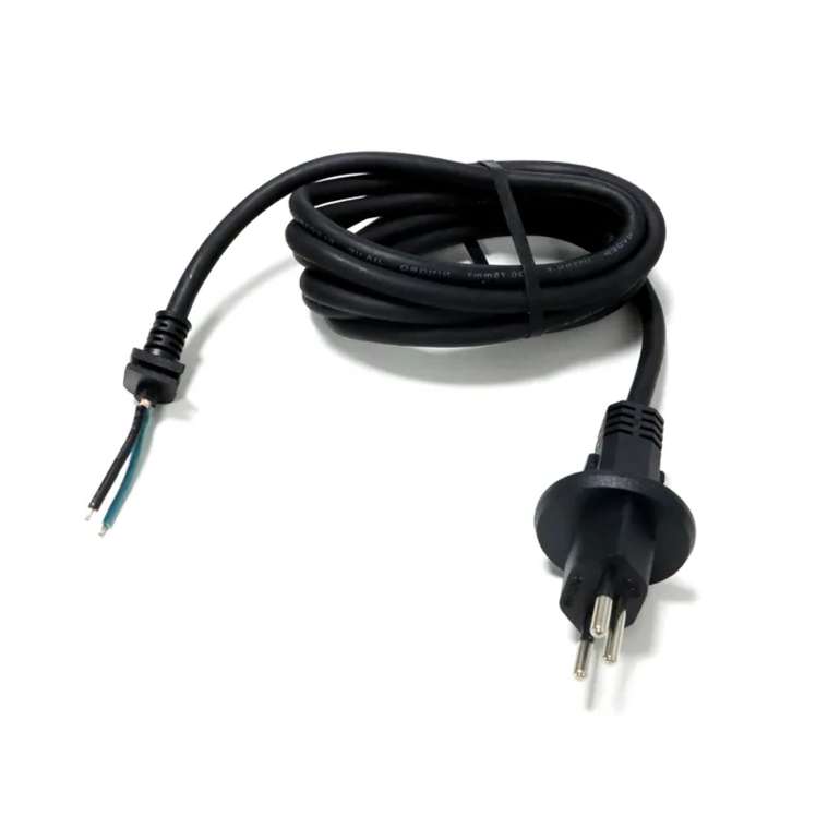
2026 New M8 Industrial Cable Assemblies: Intelligent Monitoring for Predictive Maintenance
In modern smart factories, M12 industrial cable assembliesare the backbone of sensor networks, drives, and industrial Ethernet. However, the rise of predictive maintenanceand intelligent monitoringis transforming how these cables are specified. It’s no longer just about reliable connections; it’s about building a stable data foundation for AI-driven operations.
This article explores how the latest M8 industrial cable assembliesare evolving to meet the demands of intelligent monitoring and provides practical guidance for selecting the right cables for your 2026 projects.
🎯 The New Role of M8 & M12 Cable Assemblies
M8 and M12 circular connectorsare standard in industrial settings, known for their compact, threaded design and IP65–IP67 protection. They are widely used for sensors, actuators, and fieldbus/Ethernet links in automation, automotive, and machinery.
- M8: Compact, typically 3–4 pins, for tight spaces.
- M12: More pins (up to 8), supporting data, power, and fieldbus protocols.
In a smart factory, these cables connect a vast array of sensors. If a cable fails, data is lost, and the AI’s ability to predict failures is compromised. Therefore, the reliability of M12 industrial cable assembliesis now a critical data-quality issue.
💡 What is Intelligent Monitoring & Predictive Maintenance?
Intelligent monitoringuses real-time data from sensors (vibration, temperature, current, etc.) to assess equipment health. Predictive maintenance (PdM)leverages this data with AI/ML to predict failures before they happen, shifting from reactive to proactive upkeep.
Key Advantages:
- Reduced Downtime: Unplanned outages can cost manufacturers millions annually. PdM provides early warnings, enabling timely maintenance.
- Lower Costs: PdM can reduce overall maintenance costs by 25–50% and halve failure rates by replacing parts based on condition, not a fixed schedule.
- Extended Asset Life: By operating equipment within optimal parameters, PdM reduces stress and extends its useful life.
For PdM to work, every sensor reading must be accurate and timely. This makes the quality and reliability of M12 industrial cable assembliesmission-critical.
🔌 Why Cable Quality is Non-Negotiable for PdM
- Signal Integrity: Damaged or poorly shielded cables cause data corruption (e.g., in Profinet/Ethernet systems), leading to false alarms or, worse, missed critical warnings.
- System Availability: A single failed cable can take a sensor or actuator offline. In a PdM system, this creates a “blind spot,” potentially causing the AI to miss early failure signs.
- Data Continuity: PdM relies on long-term trend analysis. Intermittent cable faults create noise in the data, confusing AI models and reducing their predictive accuracy.
- Harsh Environment Durability: Cables in robotics, conveyors, or outdoor settings face constant stress. High-flex cables with robust shielding are essential to ensure stable data for accurate PdM.
🚀 Key Features of 2026 Intelligent M8 Industrial Cable Assemblies
The new generation of M8 industrial cable assembliesis being designed with PdM in mind, featuring:
- Higher Mechanical Endurance: New PUR and TPE jackets offer millions of flex cycles, ideal for robots and AGVs, ensuring stable signals for continuous monitoring.
- Enhanced Shielding: 360° shielding combats EMI/RFI in electrically noisy environments, preventing data corruption in high-speed networks.
- IP67/IP68 Protection: Essential for washdown areas and outdoor use, ensuring reliable data transmission in any condition.
- Wide Temperature Range: New compounds function from -40°C to +85°C, suitable for harsh indoor and outdoor environments.
- Color-Coded Wires: Simplifies installation and maintenance, reducing human error in complex PdM systems.
- Integrated Strain Relief: Prevents conductor breakage from bending or pulling, ensuring a stable data link for the system’s lifespan.
🛠️ Practical Guide: Specifying Cables for PdM
When selecting M8/M12 cable assembliesfor a PdM project, consider these steps:
- Map Your Signals: Identify what each cable carries (power, analog, digital, Ethernet) and the required data rate. Use M8 for simple sensors and M12 D/X-code for high-speed Ethernet.
- Choose the Right Coding: Match the connector coding (A, B, D, X, L) to the protocol (e.g., A-code for sensors, D-code for Profinet). Mismatched codes can prevent communication entirely.
- Select Durable Jackets: Use PVC for static, cost-sensitive applications. Choose PUR for dynamic, high-flex, or oily environments. For data cables, shielded PUR is often the best choice for PdM.
- Plan for Cable Management: Use cable carriers and fixed points to minimize stress. Ensure bend radii are within the manufacturer’s specifications to prevent damage.
- Prioritize Connector Quality: Opt for overmolded connectors with gold-plated contacts for stable, low-resistance connections that last.
- Test Before Full Deployment: Run a pilot to monitor error rates and signal quality. This helps identify and correct any cable-related issues before a full rollout.
🏭 FRS: Your Partner for Intelligent-Ready Cable Assemblies
At FRS, we understand that reliable data is the cornerstone of predictive maintenance. Our M8 and M12 industrial cable assembliesare engineered to be the dependable data pathways your smart factory needs.
- Engineering-Driven: We work with you to define the perfect cable for your specific application, from connector type to jacket material.
- Rigorous Quality Control: Every assembly is tested to ensure it meets the highest standards for continuity, shielding, and mechanical performance.
- Flexible & Responsive: We offer standard products and can rapidly customize solutions to meet your unique requirements.
By partnering with FRS, you’re not just buying a cable; you’re investing in a data infrastructure that empowers your predictive maintenance strategy.
Ready to build a smarter, more reliable factory?
Contact FRS todayto discuss your M8/M12 cable assemblyneeds and how we can help you achieve seamless intelligent monitoring.
Contact Us Right Now:
TEL&WECHAT: +86-1881-875-005 (Wechat)
E-MAIL: sales@custom-cable-assemblies.com
Key Components of Industrial Cable Assemblies
Industrial environments are demanding. Think extreme temperatures, constant vibration, exposure to chemicals, oils, abrasion, and electromagnetic interference. Standard cables simply won’t survive. That’s where industrial cable assemblies come in – engineered solutions designed for reliability and longevity in the toughest conditions. But what exactly makes them so robust? Understanding the key components is crucial for selecting the right assembly for your application and ensuring smooth, uninterrupted operations.
- The Conductor: The Power or Signal Highway
- Function: The core element responsible for carrying electrical current (power) or transmitting data signals.
- Materials: Primarily copper due to its excellent conductivity. Tinned copper is common for enhanced corrosion resistance. Aluminum is used less frequently for power due to lower conductivity but can be found in some applications.
- Construction: Can be solid (single strand, less flexible) or stranded (multiple thin strands twisted together). Stranded conductors are overwhelmingly preferred in industrial assemblies for superior flexibility, essential for movement in machinery, robotics, or repeated flexing. Finer stranding (higher strand count) offers greater flexibility.
- Key Consideration: Gauge (AWG or mm²) determines current-carrying capacity. Stranding type impacts flexibility and bend radius.
- Insulation: The Essential Barrier
- Function: Electrically isolates individual conductors from each other within a multi-conductor cable, preventing short circuits. It also provides a base layer of protection.
- Materials: Chosen based on environmental demands:
- PVC (Polyvinyl Chloride): Economical, flexible, flame retardant, good general resistance. Common for less extreme environments.
- PE (Polyethylene): Excellent moisture resistance, good electrical properties. Often used for data cables.
- XLPE (Cross-Linked Polyethylene): Superior thermal rating (higher temp resistance), better abrasion and chemical resistance than standard PE. Excellent for power applications.
- TPE/TPR (Thermoplastic Elastomer/Rubber): Excellent flexibility, wide temperature range, good oil/chemical resistance. Ideal for constant flexing (e.g., drag chains).
- Silicone Rubber: Exceptional high and low-temperature flexibility, excellent flame resistance. Used in extreme heat or cold.
- FEP/PTFE (Fluoropolymers): Outstanding chemical resistance, very high temperature rating, low friction. Used in highly corrosive or ultra-high-temp environments.
- Key Consideration: Material choice is critical for temperature rating, chemical compatibility, flexibility needs, and dielectric strength.
- Shielding: Defending Against Interference
- Function: Protects the signal integrity of data or sensitive power lines by blocking Electromagnetic Interference (EMI) and Radio Frequency Interference (RFI) from external sources and preventing the cable itself from emitting interference.
- Types:
- Foil Shielding (Aluminum/Mylar): Thin layer offering 100% coverage, good for high-frequency noise. Less flexible and durable alone.
- Braided Shielding (Tinned Copper): Woven mesh offering good flexibility, durability, and effective low to medium-frequency noise protection. Coverage is typically 70-95%.
- Spiral (Serve) Shielding: Wrapped strands, highly flexible, ideal for constant flexing applications. Lower coverage than braid.
- Combination (Foil + Braid): Offers the best of both worlds – near 100% coverage from foil and durability/flexibility from braid. Common in demanding industrial data cables (e.g., Cat6A, Profinet).
- Key Consideration: Required for data cables and sensitive analog signals. Type chosen depends on the level of interference, flexibility needs, and frequency range.
- Inner Jacket (Filler/Inner Sheath – Optional but Common):
- Function: In multi-conductor cables, this component bundles the insulated (and often shielded) conductors together. It provides a round core for the outer jacket, adds strength, and can provide additional separation or protection. Fillers (like polypropylene yarn) may be used to fill gaps and maintain cable roundness.
- Key Consideration: Improves overall cable structure and crush resistance.
- Outer Jacket (Sheath): The First Line of Defense
- Function: The outermost layer, providing primary mechanical protection against abrasion, cuts, impact, crushing, chemicals, oils, sunlight (UV), moisture, and sometimes fire. It defines the cable’s overall durability and environmental resistance.
- Materials: Often similar to insulation materials but formulated for toughness:
- PVC: Common, cost-effective, good general protection, flame retardant.
- PUR (Polyurethane): Excellent abrasion, oil, chemical, and hydrolysis (water) resistance. Very flexible and durable, ideal for harsh environments and continuous flexing (e.g., robotics, drag chains).
- TPE/TPR: Excellent flexibility, wide temp range, good oil/chemical resistance.
- Neoprene (Chloroprene Rubber – CR): Excellent oil, chemical, and weather resistance, good flame retardancy. Historically common, still used.
- XLPE: High temperature and abrasion resistance.
- Key Consideration: This is the workhorse layer. Material choice is paramount based on the specific environmental hazards (abrasion, chemicals, oils, UV, temp extremes, flexing). Look for relevant ratings (e.g., UL Oil Res I/II, UL Sunlight Res).
- Connectors: The Critical Interface
- Function: Terminate the cable assembly, providing a secure, reliable, and often sealed connection to equipment (sensors, motors, controllers, PLCs, drives).
- Types: Vastly diverse – circular connectors (M8, M12, 7/8″, etc.), rectangular connectors, heavy-duty plugs/sockets, specialized connectors for Fieldbus (Profibus, CAN), Ethernet (RJ45, M12 D-coded), power (IEC, NEMA), etc.
- Key Features for Industry:
- Robust Housing: Metal (brass, stainless steel) or high-grade engineering plastic (PBT).
- IP Rating (Ingress Protection): Essential for dust and water resistance (e.g., IP65, IP67, IP69K).
- Secure Locking Mechanisms: Screw threads, bayonet locks, push-pull to prevent accidental disconnection from vibration.
- Properly Crimped/Potted Contacts: Ensures reliable electrical connection and strain relief.
- Backshells/Strain Relief: Protects the cable entry point from bending and pulling forces.
- Key Consideration: Connectors must match the equipment interface, provide the required environmental sealing (IP rating), and be rated for the voltage/current of the application. Quality of termination is critical.
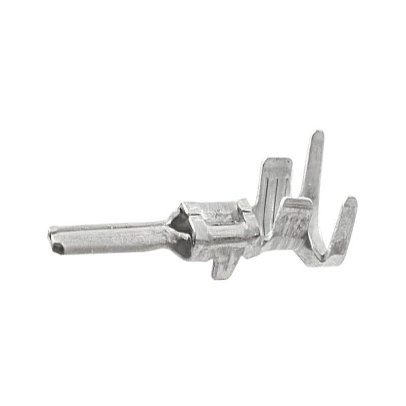
Putting it All Together: Why Component Synergy Matters
An industrial cable assembly’s performance isn’t just the sum of its parts; it’s the synergy between them. The conductor size must match the current. The insulation must withstand the voltage and temperature. The shielding must be appropriate for the signal type and noise environment. The jacket must defend against the specific physical and chemical threats. The connectors must provide a secure, sealed interface.
Choosing an assembly with mismatched components – like a highly flexible PUR jacket but with foil shielding unsuitable for constant flexing – leads to premature failure. Understanding these key components empowers engineers, maintenance personnel, and purchasers to:
- Specify accurately: Match the assembly precisely to the application’s electrical, mechanical, and environmental demands.
- Improve reliability: Select assemblies built to withstand the specific challenges of the industrial setting, minimizing downtime.
- Enhance safety: Ensure components meet necessary flame retardancy and electrical safety standards (UL, CSA, CE, etc.).
- Optimize cost: Avoid over-engineering or, more critically, under-engineering by selecting the right level of protection.
Materials Science of Chemical-Resistant Cable Assemblies
In industries ranging from oil and gas to pharmaceuticals, chemical-resistant cable assemblies are critical components that ensure safety, reliability, and longevity in harsh environments. Exposure to aggressive chemicals, extreme temperatures, and abrasive conditions can degrade standard cables, leading to equipment failure, safety hazards, and costly downtime. This article explores the materials science behind chemical-resistant cable assemblies, offering insights into their design, applications, and best practices for selection and maintenance.
The Threat of Chemical Exposure on Cables
Chemical corrosion is a silent destroyer of cable assemblies. Acids, alkalis, solvents, oils, and industrial cleaning agents can attack traditional cable materials, causing:
- Insulation breakdown: Loss of dielectric strength, leading to short circuits.
- Jacket degradation: Cracking, swelling, or hardening, exposing internal conductors.
- Connector failure: Corrosion of metal contacts, disrupting signal or power transmission.
To combat these risks, engineers rely on advanced polymers and composite materials engineered for chemical resistance, thermal stability, and mechanical durability.
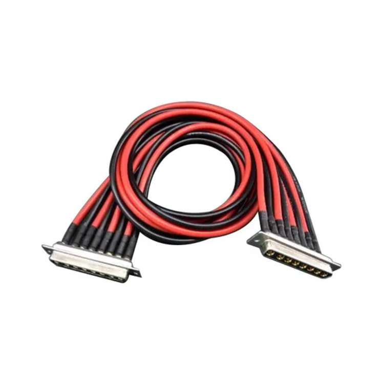
Key Materials in Chemical-Resistant Cable Assemblies
1. Insulation Materials
The insulation layer protects conductors from electrical leakage. Common chemically resistant options include:
- PTFE (Polytetrafluoroethylene): Withstands temperatures up to 260°C and resists almost all industrial chemicals. Ideal for high-temperature environments like chemical processing plants.
- FEP (Fluorinated Ethylene Propylene): Similar to PTFE but with lower temperature resistance (200°C). Easier to process and suitable for moderately harsh conditions.
- PFA (Perfluoroalkoxy): Combines PTFE’s chemical resistance with melt-processability, used in semiconductor manufacturing.
2. Jacket/Sheathing Materials
The outer jacket shields cables from physical and chemical damage. Top choices include:
- TPU (Thermoplastic Polyurethane): Resists oils, fuels, and abrasion. Widely used in automotive and marine applications.
- CPE (Chlorinated Polyethylene): Affordable and effective against acids, alkalis, and ozone. Common in wastewater treatment facilities.
- Viton® (Fluoroelastomer): Exceptionally resistant to hydrocarbons and solvents, ideal for oil refineries.
3. Connector and Seal Materials
- Stainless Steel or Nickel-Plated Connectors: Resist corrosion from acids and saltwater.
- Silicone Seals: Provide watertight, chemical-resistant barriers in connectors.
Applications of Chemical-Resistant Cable Assemblies
- Oil & Gas: Exposure to hydrocarbons, H2S, and drilling fluids.
- Pharmaceuticals: Sterilization processes using ethanol, hydrogen peroxide, or ethylene oxide.
- Wastewater Treatment: Resistance to chlorine, sulfuric acid, and biological agents.
- Food & Beverage: Sanitization with caustic cleaners and steam.
How to Choose the Right Chemical-Resistant Cable
Selecting the optimal cable assembly requires evaluating:
- Chemical Compatibility: Match materials to the specific chemicals in your environment (consult ASTM D543 or ISO 1817 test standards).
- Temperature Range: Ensure materials can withstand operational and peak temperatures.
- Mechanical Stress: Consider abrasion, flexing, and UV exposure.
- Certifications: Look for UL, CSA, or ATEX ratings for safety compliance.
Maintenance and Inspection Best Practices
- Regular Inspections: Check for cracks, discoloration, or swelling in jackets.
- Cleanliness: Rinse cables exposed to corrosive residues promptly.
- Documentation: Track chemical exposure history to predict lifespan.
Future Trends in Material Science
Emerging materials like nanocomposites (e.g., graphene-enhanced polymers) and bio-based fluoroelastomers are pushing the boundaries of chemical resistance while addressing sustainability concerns. Meanwhile, smart cables with embedded sensors can now monitor degradation in real time.
wire connectors for industrial cables
In the complex ecosystem of industrial operations, wire connectors for industrial cables serve as the unsung heroes that ensure seamless and reliable electrical connectivity. These small yet critical components are responsible for joining cables, transmitting power and signals across various industrial equipment, and maintaining the integrity of electrical systems even in harsh operating environments. From manufacturing plants and power generation facilities to automotive assembly lines and oil refineries, the performance of industrial cable wire connectors directly impacts productivity, safety, and operational efficiency.
Main Types of Wire Connectors for Industrial Cables
Understanding the different types of wire connectors is essential for selecting the right solution for specific industrial applications. Here are some of the most common varieties:
- Crimp Connectors: These connectors create a secure bond by compressing a metal sleeve around the cable conductor. They are widely used due to their simplicity, cost-effectiveness, and high mechanical strength. Crimp connectors are suitable for applications with moderate vibration and temperature ranges, such as in general industrial machinery and automotive wiring harnesses. Proper crimping tools and techniques are crucial to ensure a low-resistance connection that resists corrosion.
- Insulation-Displacement Connectors (IDCs): IDCs eliminate the need for stripping cable insulation, as they pierce the insulation to make contact with the conductor. This feature speeds up installation and reduces the risk of human error. They are ideal for high-volume wiring applications, such as in telecommunications equipment and control panels. IDCs provide consistent performance when used with the correct wire gauge and insulation type.
- Threaded Connectors: Characterized by their screw-on design, threaded connectors offer excellent environmental sealing and mechanical stability. They are commonly used in harsh environments where dust, moisture, or chemicals are present, such as in outdoor industrial installations, marine applications, and oil and gas facilities. Threaded connectors often feature O-rings or gaskets to prevent ingress and ensure long-term reliability.
- Terminal Blocks: These are modular connectors that allow multiple cables to be connected in a single location. They come in various configurations, including feed-through, ground, and fuse blocks, making them versatile for different wiring needs. Terminal blocks are widely used in control cabinets, distribution panels, and automation systems, as they simplify wiring management and facilitate easy maintenance and troubleshooting.
Key Factors to Consider When Selecting Wire Connectors
Choosing the appropriate wire connector for industrial cables requires careful evaluation of several factors to ensure optimal performance and safety:
- Current and Voltage Ratings: The connector must be capable of handling the maximum current and voltage of the electrical system it will be part of. Using a connector with insufficient ratings can lead to overheating, insulation damage, and even electrical fires. Always check the manufacturer’s specifications to match the connector’s ratings with the application requirements.
Industrial Cable Assemblies for Vision Systems: Key Considerations for Reliable Performance
In modern manufacturing, vision systems have become indispensable for tasks like quality inspection, part positioning, and process monitoring. These systems rely on high-speed data transmission between cameras, light sources, controllers, and computers—all made possible by industrial cable assemblies. Unlike standard cables, those designed for vision systems must withstand harsh industrial environments while maintaining signal integrity, making their selection and implementation critical to overall system efficiency.
1. The Critical Role of Cable Assemblies in Vision System Performance
Vision systems depend on unbroken, high-fidelity data streams to capture clear images and deliver accurate analytics. Industrial cable assemblies act as the “nervous system” of these setups, and their failure or poor performance can lead to:
- Data loss or corruption: Resulting in blurry images, missed defects, or incorrect part identification.
- System downtime: Costly delays in production lines, especially in high-volume manufacturing.
- Inconsistent results: Even minor signal interference can skew inspection data, leading to false rejects or accepts.
For example, a vision system inspecting automotive components requires cables that transmit 4K or 8K image data in real time. A subpar cable assembly might drop frames or introduce noise, causing the system to miss critical flaws like cracks or misalignments.
2. Key Performance Requirements for Vision System Cable Assemblies
Industrial environments pose unique challenges—including electromagnetic interference (EMI), temperature fluctuations, mechanical stress, and exposure to oils or chemicals. Cable assemblies for vision systems must meet specific standards to overcome these:
High-Speed Data Transmission
Vision protocols like GigE Vision, USB3 Vision, and CoaXPress demand cables that support bandwidths from 1 Gbps (GigE) to 12.5 Gbps (CoaXPress 2.0). This requires:
- Thick, high-purity copper conductors to minimize signal resistance.
- Precision twisting of pairs (for Ethernet/USB) to reduce crosstalk between wires.
EMI/RFI Shielding
Factories are filled with EMI sources—motors, variable frequency drives (VFDs), and welding equipment—that can disrupt vision system signals. Effective shielding options include:
- Foil shielding: Lightweight and cost-effective for low-interference areas.
- Braided shielding: Offers 85–95% coverage, ideal for high-EMI environments like automotive plants.
- Dual shielding (foil + braid): Maximum protection for critical applications (e.g., aerospace component inspection).
Environmental Durability
Cable assemblies must endure extreme conditions common in manufacturing:
- Temperature resistance: Operating ranges from -40°C (cold storage) to 85°C (foundries) or higher, depending on the material (e.g., PTFE insulation for high heat).
- Mechanical resilience: Resistance to abrasion, bending, and vibration (critical for robotic vision systems with moving parts).
- Chemical resistance: Protection against oils, coolants, and solvents (using materials like PUR or TPE jackets).
3. Essential Selection Factors for Industrial Cable Assemblies
Choosing the right cable assembly requires aligning its specs with your vision system’s needs and environment:
1. Interface Compatibility
Match the cable to your system’s connectors, which are standardized for vision applications:
- M12 connectors: Common for GigE Vision (X-coded for 10Gbps) and USB3 Vision (A-coded), offering IP67/IP68 dust/water protection.
- USB Type-C: Used for compact vision cameras, supporting USB4 Vision’s high bandwidth.
- BNC/TNC: For CoaXPress systems, ideal for long-distance (up to 100m) high-speed transmission.
2. Cable Length and Signal Loss
Longer cables increase signal attenuation (weakening). For distances:
- Up to 10m: Standard USB3/GigE cables work.
- 10–100m: Use active cables (with built-in signal boosters) or fiber optic assemblies (for zero EMI interference).
3. Customization Needs
Many manufacturing setups have unique constraints—e.g., tight spaces, robotic arm movement, or custom connector combinations. Off-the-shelf cables may not fit, so look for suppliers that offer custom lengths, connector configurations, and shielding options.
4. Installation and Maintenance Best Practices
Even high-quality cable assemblies will underperform without proper installation and care:
- Route cables away from EMI sources: Keep vision system cables at least 30cm from power cables or VFDs to reduce interference.
- Use cable management tools: Employ drag chains for moving components (e.g., robotic vision) to prevent bending stress, and cable glands for IP-rated enclosures.
- Regular inspections: Check for frayed jackets, loose connectors, or damaged shielding monthly—replace worn assemblies immediately to avoid system failures.
About FRS: Your Trusted Partner for Vision System Cable Assemblies
When reliability and performance matter for your vision system, FRS stands as a leading factory specializing in industrial cable assemblies tailored to vision applications. We design and manufacture solutions that meet the strictest standards:
- Customization: Our engineering team creates assemblies matching your interface (M12, USB-C, CoaXPress), length, and shielding needs—even for tight or high-motion setups.
- Durability: We use high-purity copper conductors, dual-shielding (foil + braid), and chemical-resistant PUR/TPE jackets to withstand extreme industrial environments (-40°C to 125°C).
- Performance: Every FRS cable assembly is tested for signal integrity, ensuring compatibility with GigE Vision, USB3 Vision, and CoaXPress protocols—guaranteeing zero data loss or interference.
With FRS, you get more than a cable assembly: you get a partner committed to minimizing your vision system downtime and maximizing inspection accuracy. Let us build the right solution for your manufacturing needs.
If you need a tailored cable assembly solution for your vision system, I can help draft a custom FRS product inquiry template that outlines key specs (interface, environment, length) to streamline your communication with the factory—would you like that?
Cable Assembly Technical Specification
1.Core Design Specifications
A. Conductor Requirements
Material:
Copper (bare, tinned, or silver-plated) for high conductivity.
Aluminum for lightweight, high-voltage power transmission.
Fiber optic strands for data-centric applications.
Gauge/Size:
Defined by AWG (American Wire Gauge) standards (e.g., 24 AWG for signal cables, 4/0 AWG for power lines).
Stranding:
Stranded conductors for flexibility (e.g., 19/34 stranding for robotics).
Solid conductors for fixed installations.
B. Insulation Specifications
Material:
Material Temp Range Dielectric Strength Key Applications
PVC -40°C–105°C 10–20 kV/mm Consumer electronics
XLPE -40°C–150°C 20–30 kV/mm Solar farms, EV charging
Silicone -60°C–200°C 15–25 kV/mm Aerospace, foundries
PTFE -200°C–260°C 40–60 kV/mm Chemical plants, military
Thickness:
Compliance with IEC 60228 (e.g., 0.7 mm insulation for 600V rated cables).
C. Jacket/Sheath Properties
Material Selection:
PUR: Abrasion- and oil-resistant (IP69K rating for washdown environments).
LSZH: Low smoke, zero halogen for public infrastructure.
TPE: UV-resistant for outdoor use.
Protective Features:
Armoring (steel braid) for crush resistance.
EMI shielding (foil + braid) for signal integrity.
2. Electrical Performance Standards
Voltage Rating:
Low Voltage (≤1 kV): IEC 60227 for household wiring.
Medium/High Voltage (1 kV–500 kV): IEC 60502 for power distribution.
Current Capacity:
Based on conductor size and insulation thermal limits (e.g., 30A for 10 AWG copper at 75°C).
Impedance and Attenuation:
Critical for high-frequency data cables (e.g., 100Ω ±5Ω for USB 3.0).
3. Mechanical and Environmental Specifications
Flex Life:
≥1 million cycles for robotic cables (tested per IEC 63076).
Bend Radius:
Minimum 8x cable diameter for standard installations.
Temperature Tolerance:
Operating range: -60°C to 260°C (e.g., PTFE-insulated aerospace cables).
Ingress Protection (IP):
IP67/IP68 for waterproofing in marine or outdoor applications.
Chemical Resistance:
Compatibility with oils, acids, and solvents per ISO 6722.
4. Safety and Compliance Certifications
Flame Resistance:
UL 1685 (vertical tray flame test) for plenum-rated cables.
IEC 60332-1 for flame-retardant standards.
Environmental Compliance:
RoHS/REACH: Restrict hazardous substances (e.g., lead, phthalates).
WEEE: Recycling and disposal guidelines.
Industry-Specific Certifications:
Automotive: ISO 19642, LV214 (German automotive standards).
Aerospace: AS23053/4 for Mil-Spec connectors.
Medical: ISO 13485 for biocompatibility.
5. Testing Protocols
Electrical Testing:
Hi-Pot Testing: Verify insulation integrity at 2x rated voltage + 1 kV.
Continuity Testing: Ensure no conductor breaks.
Mechanical Testing:
Tensile Strength: ≥50 N/mm² for industrial cables.
Torsional Flexibility: ±180°/meter for dynamic applications.
Environmental Testing:
Thermal Cycling: -40°C to 150°C for 500 cycles (MIL-STD-810).
Salt Spray Testing: 720 hours for marine-grade assemblies (ASTM B117).
6. Application-Specific Specifications
A. Industrial Automation
Standards: UL 508A, ISO 13849.
Key Specs:
Drag chain-rated jackets (PUR or TPE).
M12/M8 connectors with IP67 sealing.
B. Automotive
Standards: SAE J1128, LV214.
Key Specs:
Thin-wall insulation (0.3 mm) for weight reduction.
125°C temperature rating for engine compartments.
C. Aerospace
Standards: AS6070, MIL-DTL-38999.
Key Specs:
PTFE insulation for -65°C to 200°C range.
Quadrax shielding for EMI protection.
D. Data Centers
Standards: TIA-568, ISO/IEC 11801.
Key Specs:
Cat6A/Cat7 shielded twisted pairs.
LSZH jackets for fire safety.
7. Documentation and Labeling Requirements
Markings:
Voltage rating, gauge, manufacturer, and compliance marks (UL, CE) printed on the jacket.
Traceability:
Lot numbers and date codes for quality control.
Datasheets:
Detailed specs for impedance, capacitance, and attenuation.
8. Top Industry Standards
Standard Scope Key Parameters
IEC 60228 Conductor sizing and resistance Stranding, DC resistance
UL 44 Thermoset-insulated wires Flame resistance, dielectric
MIL-DTL-17 Military coaxial cables Shielding, frequency range
EN 50575 EU CPR (Construction Products) Fire performance, smoke emission
Aerospace Firms Craft Lightweight Cables: Revolutionizing the Skies
In the aerospace industry, where every ounce matters, lightweight cables have emerged as a game-changer. These cables not only reduce the overall weight of aircraft and spacecraft but also enhance performance, efficiency, and safety. Let’s explore how aerospace firms are crafting these innovative cables and the solutions they offer.
The Need for Lightweight Cables
Traditional cables used in aerospace applications are often heavy, which adds unnecessary weight to vehicles. This extra weight leads to increased fuel consumption, reduced range, and higher operating costs. For instance, a study by [Renowned Aerospace Research Institute] found that reducing cable weight by just 10% can lead to a 3% decrease in fuel consumption for commercial aircraft.
Lightweight cables address these issues by utilizing advanced materials and manufacturing techniques. They offer the same electrical conductivity and mechanical strength as traditional cables but at a fraction of the weight.
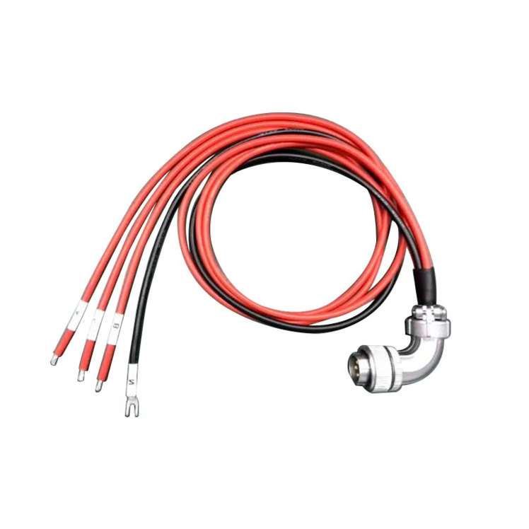
Materials and Manufacturing Techniques
Aerospace firms are turning to high-performance materials such as advanced polymers, carbon fibers, and composite materials to create lightweight cables. These materials have excellent electrical and mechanical properties, making them ideal for aerospace applications.
For example, polyetheretherketone (PEEK) is a popular choice due to its high temperature resistance, chemical stability, and low density. Carbon fiber-reinforced polymers are also used to enhance the strength and durability of the cables while keeping the weight down.
In terms of manufacturing, techniques like extrusion and braiding are commonly employed. Extrusion allows for the precise shaping of the cable insulation and jacket, while braiding provides additional mechanical protection and flexibility.
Solutions for Aerospace Applications
- Fuel Efficiency Improvement: By replacing heavy traditional cables with lightweight ones, aerospace companies can significantly reduce the weight of their vehicles. This directly translates into lower fuel consumption and longer ranges, which is crucial for both commercial airlines and space missions.
- Enhanced Performance: Lightweight cables offer better flexibility and durability, reducing the risk of cable failures. This improves the overall reliability of the electrical systems in aircraft and spacecraft, minimizing downtime and maintenance costs.
- Space and Weight Savings: In spacecraft, where every cubic inch of space is precious, lightweight cables take up less room, allowing for more equipment and payloads to be carried. Their reduced weight also enables more efficient use of launch vehicles.
- Safety Enhancement: These cables are designed to withstand harsh aerospace environments, including extreme temperatures, radiation, and vibrations. Their reliability ensures the safety of passengers and crew during flights and space missions.
Case Studies
[Leading Aerospace Company] recently replaced traditional copper cables in its new aircraft model with lightweight composite cables. As a result, the aircraft’s weight was reduced by 200 kilograms, leading to an annual fuel savings of over [X] liters per plane. Another space agency used lightweight cables in its latest satellite, enabling it to carry more scientific instruments without increasing the launch weight.
In conclusion, the development of lightweight cables by aerospace firms is a significant step forward in the industry. By leveraging advanced materials and manufacturing techniques, these cables offer practical solutions to the challenges of weight, performance, and efficiency. As the demand for more fuel-efficient and reliable aerospace vehicles grows, lightweight cables will play an increasingly vital role in shaping the future of the industry.
5G Sparks Smart Cable Innovations
The rollout of 5G technology isn’t just about faster smartphones or smoother video streaming—it’s revolutionizing the backbone of connectivity itself. One of the most exciting outcomes of this transformation is the rise of smart cables. In this article, we’ll break down how 5G is driving smart cable innovations, why they matter to you, and how they solve real-world connectivity challenges.
Why 5G Demands Smarter Cables
5G networks operate at higher frequencies and deliver data speeds up to 100x faster than 4G. But this leap comes with challenges:
- Signal interference: Higher-frequency waves struggle to penetrate walls and obstacles.
- Heat management: Faster data transmission generates more heat.
- Power efficiency: Devices need to stay connected without draining battery life.
Traditional cables aren’t built to handle these demands. Enter smart cables—engineered to optimize performance, durability, and adaptability in the 5G era.
What Are Smart Cables?
Smart cables integrate advanced materials, sensors, and AI-driven features to address 5G’s unique requirements. Key innovations include:
- Enhanced Shielding
- Built-in electromagnetic interference (EMI) shielding to reduce signal loss.
- Example: Gold-plated connectors and braided shielding for stable high-speed data transfer.
- Self-Regulating Temperature
- Heat-resistant materials and cooling technologies prevent overheating during heavy usage.
- Adaptive Power Delivery
- Smart cables adjust power output based on device needs, improving energy efficiency.
- IoT Compatibility
- Embedded sensors enable real-time monitoring of cable health (e.g., wear and tear, connection stability).
Real-World Applications: Solving Everyday Problems
Smart cables aren’t just for tech enthusiasts—they’re designed to simplify your life:
- Smart Homes: Streamline 4K/8K video streaming, gaming, and smart device connectivity without lag.
- Industrial IoT: Enable reliable machine-to-machine communication in factories.
- Healthcare: Support high-bandwidth medical imaging and remote diagnostics.
- Electric Vehicles (EVs): Faster charging and safer power management for next-gen EVs.
How to Choose the Right Smart Cable
Not all smart cables are created equal. Look for these features:
- Bandwidth: Supports at least 10 Gbps for future-proofing.
- Durability: Nylon braiding or reinforced connectors for longevity.
- Certifications: USB-IF, Thunderbolt™, or Qi wireless charging compliance.
- Compatibility: Works with your 5G devices (smartphones, routers, IoT gadgets).
The Future of Smart Cables
As 5G expands, smart cables will evolve with even smarter capabilities:
- AI-Powered Optimization: Cables that learn usage patterns to optimize performance.
- Eco-Friendly Designs: Recyclable materials and low-energy manufacturing.
- Seamless Integration: Plug-and-play compatibility with 6G and beyond.
Industrial Cable Assemblies for PLC Systems: Key Considerations for Reliable Industrial Control
In industrial automation, Programmable Logic Controllers (PLCs) serve as the “brain” of control systems, orchestrating machinery, processes, and data flow across factories. Yet, even the most advanced PLCs depend entirely on industrial cable assemblies to transmit critical signals, power, and data between sensors, actuators, HMIs (Human-Machine Interfaces), and other peripherals. A poorly designed or mismatched cable assembly can lead to signal loss, system downtime, or even equipment failure—making the selection and implementation of these components a make-or-break factor for industrial efficiency.
1. Key Functional Requirements for PLC Cable Assemblies
PLC systems operate in harsh industrial environments, so cable assemblies must meet strict performance standards to ensure reliability. Below are non-negotiable functional requirements:
- Signal Integrity: PLCs rely on precise analog/digital signals (e.g., 4-20 mA current loops, Ethernet-based PROFINET/Modbus) to control processes. Cable assemblies must maintain consistent impedance (typically 50Ω for coaxial or 100Ω for twisted-pair) and minimize signal attenuation, even over extended distances (up to 100 meters for Ethernet-based PLC networks).
- Electromagnetic Interference (EMI) Resistance: Factories are filled with noise sources—motors, transformers, and high-voltage equipment—that can disrupt PLC signals. Quality cable assemblies use multi-layer shielding (e.g., aluminum foil + tinned copper braid) and twisted-pair conductors to block EMI, complying with international standards like IEC 61000-6-2 (industrial EMC immunity).
- Environmental Durability: Industrial spaces expose cables to extreme temperatures (-40°C to 85°C for most applications), oil, chemicals, moisture, and mechanical abrasion. Cable jackets made from materials like PVC, PUR (polyurethane), or TPE (thermoplastic elastomer) resist these hazards, while ruggedized connectors (e.g., M12, D-Sub with IP67/IP68 ratings) prevent water or dust ingress.
2. Critical Selection Criteria for PLC Cable Assemblies
Choosing the right cable assembly requires aligning components with your PLC system’s specific needs. Focus on these criteria:
- Connector Compatibility: Match connectors to your PLC’s port type. Common options include:
- D-Sub connectors (DB9, DB25): For legacy PLCs and serial communication (RS-232/RS-485).
- M12 connectors: For industrial Ethernet (PROFINET, EtherNet/IP) and sensor/actuator links, ideal for tight spaces.
- Terminal blocks: For power transmission to PLC modules, ensuring secure wire termination.
- Cable Length & Gauge: Avoid overly long cables (which increase signal loss) or undersized gauges (which cause voltage drops). For example, 22 AWG (American Wire Gauge) cables work for short-distance signal transmission, while 18 AWG is better for power-hungry PLC modules.
- Certifications: Prioritize assemblies certified by global bodies like UL (for safety in North America), CE (for EU compliance), or CSA (Canadian Standards Association). Certifications guarantee that cables meet fire, electrical, and environmental safety standards.
3. Installation & Maintenance Best Practices
Even high-quality cable assemblies fail if installed or maintained improperly. Follow these guidelines to extend their lifespan:
- Route Cables Strategically: Keep PLC signal cables separate from high-voltage power cables (minimum 30cm gap) to reduce cross-interference. Use cable trays or conduits to avoid kinking or mechanical damage from machinery.
- Secure Connections: Tighten connectors to the manufacturer’s torque specifications (e.g., 0.5–1 N·m for M12 connectors) to prevent loose contacts, which cause intermittent signal drops. Avoid over-tightening, as this can damage connector pins.
- Regular Inspections: Check cable assemblies every 3–6 months for signs of wear—cracked jackets, corroded connectors, or frayed shielding. Replace damaged assemblies immediately to prevent system downtime.
4. The Value of Customized Solutions
Many industrial applications require non-standard cable assemblies—for example, a food-processing plant may need FDA-approved, oil-resistant cables, or a automotive factory may need ultra-flexible cables for robotic PLC arms. Off-the-shelf assemblies often fail to meet these unique needs, leading to compromised performance. Customized PLC cable assemblies, tailored to your environment, signal type, and length requirements, eliminate these risks and ensure seamless integration with your control system.
Choose FRS: Your Trusted Partner for PLC Cable Assemblies
When reliability and performance matter, FRS stands out as a leading factory specializing in industrial cable assemblies for PLC systems. With decades of experience in industrial automation, we design and manufacture solutions that meet the strictest standards:
- Customization: We build cable assemblies to your exact specifications—from connector type and shielding to jacket material and length—ensuring perfect compatibility with your PLC brand (Siemens, Allen-Bradley, Mitsubishi, etc.).
- Quality Assurance: Every FRS cable assembly undergoes rigorous testing, including signal integrity checks, EMI resistance validation, and environmental durability trials, with certifications like UL, CE, and IP67/IP68.
- Global Support: We deliver fast lead times (5–7 business days for standard orders) and dedicated after-sales service, helping you minimize downtime and keep your PLC systems running smoothly.
For PLC cable assemblies that combine durability, precision, and tailored design, FRS is your one-stop factory solution.
Environmental Adaptation Design for Cable Assemblies in Wind Power Systems
Wind power systems operate in some of the planet’s most challenging environments—offshore platforms, deserts, mountainous regions, and icy tundras. These conditions demand robust infrastructure, and cable assemblies are no exception. As the backbone of energy transmission and control in wind turbines, cables must withstand extreme temperatures, moisture, UV exposure, vibrations, and chemical corrosion. This article explores environmental adaptation design strategies for cable assemblies in wind power systems, offering actionable insights for engineers, procurement teams, and maintenance professionals.
1. Why Environmental Adaptation Matters for Wind Power Cables
Wind turbines are exposed to:
- Temperature extremes: From -40°C in Arctic regions to 50°C in desert climates.
- Humidity and salt spray: Offshore installations face relentless moisture and corrosive saltwater.
- Mechanical stress: Turbine vibrations and cable bending during installation/maintenance.
- UV radiation: Prolonged sunlight degrades unprotected materials.
Failure to address these factors leads to insulation breakdown, signal interference, and costly downtime. For example, a study by Windpower Engineering & Development found that cable failures account for 15–20% of wind turbine downtime, emphasizing the need for resilient designs.
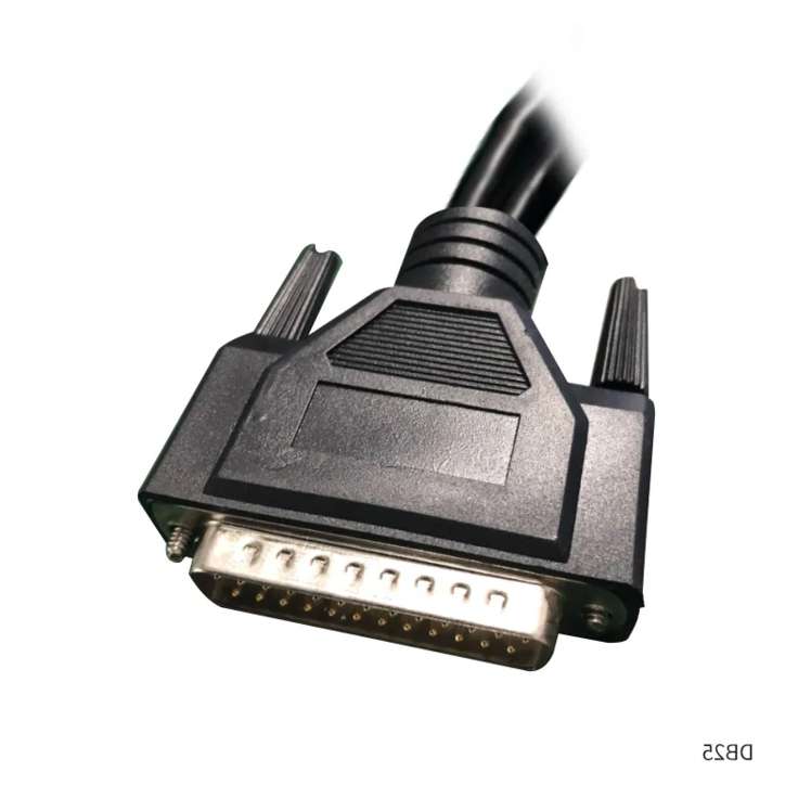
2. Key Design Strategies for Harsh Environment Cable Assemblies
A. Material Selection: Balancing Durability and Flexibility
- Insulation: Thermoplastic polyurethane (TPU) and cross-linked polyethylene (XLPE) resist temperature fluctuations and abrasion.
- Jacketing: Halogen-free, flame-retardant materials like LSZH (Low Smoke Zero Halogen) enhance safety in fire-prone areas.
- Shielding: Multi-layer aluminum or copper shielding minimizes electromagnetic interference (EMI) from nearby turbines.
Pro Tip: Offshore projects benefit from polyurethane (PUR) jacketing, which repels saltwater and resists hydrolysis.
B. Sealing and Connector Protection
- IP68/IP69K-rated connectors: Prevent ingress of dust, water, and chemicals.
- Overmolded junctions: Eliminate weak points where cables connect to terminals.
- Corrosion-resistant coatings: Zinc-nickel alloys or epoxy layers protect metallic components in salty air.
Case Study: A German offshore wind farm reduced cable replacement costs by 30% after switching to IP69K-rated connectors with silicone sealing.
C. Thermal Management Solutions
- High-temperature conductors: Nickel-plated or silver-coated wires handle heat from internal turbine electronics.
- Ventilated cable trays: Improve airflow to prevent overheating in nacelles.
- Phase-change materials (PCMs): Absorb excess heat during peak loads.
3. Addressing Corrosion: The Silent Killer of Offshore Cables
Saltwater accelerates corrosion, especially in submerged or splash zones. Solutions include:
- Stainless steel braiding: Adds mechanical strength while resisting rust.
- Cathodic protection: Sacrificial anodes divert corrosive currents away from critical components.
- Regular inspections: Ultrasonic testing detects early signs of pitting or galvanic corrosion.
Industry Insight: The International Electrotechnical Commission (IEC) standard IEC 60228-5 outlines corrosion-resistant requirements for submarine cables.
4. Testing and Certification: Validating Cable Performance
Reliable cable assemblies must pass rigorous tests:
- Temperature cycling: Expose cables to -40°C to 125°C to simulate real-world conditions.
- Salt spray testing: ASTM B117 evaluates corrosion resistance.
- Flex life testing: Ensures cables endure repeated bending without cracking.
Look for certifications like UL 4703 (photovoltaic and wind turbine cables) or IEC 61439 (low-voltage switchgear).
5. Maintenance Best Practices for Longevity
- Annual thermographic inspections: Identify hotspots caused by insulation wear.
- Clean connectors regularly: Salt and dust buildup increases resistance and fire risks.
- Monitor tension: Excessive pulling force during installation damages conductors.
Industrial Cable for Machinery
In the complex ecosystem of industrial machinery, every component plays a pivotal role in ensuring seamless operation, and industrial cables stand out as the unsung heroes. These cables are not mere conductors of electricity or data; they are the lifelines that connect critical parts of machinery, enabling precise control, power transmission, and real-time data exchange. Unlike standard cables, industrial cables for machinery are engineered to withstand the harshest operating conditions, making them indispensable in sectors such as manufacturing, automotive, aerospace, and energy.
Key Characteristics of High-Quality Industrial Machinery Cables
The performance of industrial machinery heavily relies on the quality of its cables. High-quality industrial cables for machinery possess several defining characteristics that set them apart from conventional options.
- Mechanical Durability: Industrial environments are rife with physical stressors such as abrasion, impact, and continuous flexing. Premium cables are constructed with robust outer jackets made from materials like PVC, PUR (polyurethane), or TPE (thermoplastic elastomer). These materials offer exceptional resistance to wear and tear, ensuring the cables can endure repeated movement—common in robotic arms, conveyor systems, and packaging machinery—without compromising their structural integrity.
- Environmental Resistance: Machinery operates in diverse environments, from high-temperature foundries to damp food processing plants and chemical facilities. Industrial cables are designed to resist extreme temperatures (ranging from -40°C to 150°C or higher), moisture, oils, chemicals, and UV radiation. For example, cables used in oil and gas applications are formulated to repel hydrocarbons, while those in pharmaceutical settings are made with non-toxic, easy-to-clean materials that meet strict hygiene standards.
- Electrical Performance: Stable electrical conductivity and insulation are non-negotiable. Industrial cables feature high-purity copper conductors that minimize resistance and ensure efficient power delivery. The insulation materials, such as XLPE (cross-linked polyethylene) or EPR (ethylene propylene rubber), provide excellent dielectric strength, preventing electrical leakage and interference. This is crucial for sensitive machinery like CNC machines, where even minor electrical fluctuations can lead to precision errors.
- Flexibility and Torsion Resistance: Many industrial machines require cables to bend, twist, or rotate continuously. Cables with stranded conductors and flexible jackets offer superior flexibility, allowing them to adapt to dynamic movements without breaking. Torsion-resistant cables, in particular, are essential for machinery with rotating components, such as wind turbines or printing presses, as they can withstand twisting forces without signal degradation.
Essential Considerations for Selecting Industrial Cables for Machinery
Choosing the right industrial cable for machinery is a critical decision that impacts operational efficiency, safety, and maintenance costs. Here are key factors to consider during the selection process:
- Application-Specific Requirements: Start by defining the cable’s purpose—whether it’s for power transmission, data communication, or signal control. For power cables, consider the voltage rating and current capacity to match the machinery’s power needs. Data cables, such as Ethernet or Profinet cables, require high bandwidth and low signal attenuation to support real-time communication in automated systems. Additionally, identify the machinery’s operating environment (temperature, moisture, chemicals) to select a cable with the appropriate environmental resistance.
- Mechanical Stress Factors: Evaluate the level of movement the cable will undergo. If the machinery involves linear motion (e.g., a sliding door in a factory) or repetitive flexing (e.g., a robotic arm), opt for a flex-rated cable with a minimum bend radius specified by the manufacturer. For cables that will be subjected to torsion, choose those designed with a twist-resistant core to avoid conductor breakage.
- Regulatory Compliance: Different industries have strict regulations governing cable safety and performance. For instance, cables used in hazardous environments (ATEX zones) must be flame-retardant and explosion-proof. In the automotive industry, cables must meet ISO standards for heat and oil resistance. Ensure the selected cable complies with relevant certifications to avoid regulatory penalties and ensure workplace safety.
- Long-Term Reliability: Invest in cables from reputable manufacturers that offer consistent quality. While budget-friendly options may seem attractive, they often lack durability and can lead to frequent replacements, causing unplanned downtime. Consider the cable’s expected service life and warranty terms to assess its long-term value.
Installation and Maintenance Best Practices
Proper installation and maintenance are vital to maximizing the lifespan of industrial cables for machinery.
Installation Tips: Avoid over-bending cables beyond their specified minimum bend radius, as this can damage the insulation and conductors. Use cable glands and protective conduits to shield cables from physical damage and environmental contaminants. Ensure secure termination to prevent loose connections, which can cause arcing and overheating. For dynamic applications, use cable tracks or carriers to guide the cables and reduce stress during movement.
Maintenance Practices: Regularly inspect cables for signs of wear, such as cracks in the jacket, exposed conductors, or fraying. Clean cables periodically to remove dust, oil, or chemical residues that can degrade the insulation. Monitor cable performance using diagnostic tools to detect electrical issues early, such as increased resistance or signal interference. Replace damaged cables promptly to avoid machinery breakdowns or safety hazards.
Future Trends in Industrial Machinery Cables
As industrial automation and digitalization advance, the demand for smarter, more advanced cables is growing. One key trend is the development of integrated cables that combine power transmission and data communication, reducing cable clutter and simplifying installation. Another trend is the use of eco-friendly materials, such as recyclable jackets and halogen-free insulation, to meet sustainability goals. Additionally, cables with built-in sensors are emerging, enabling real-time monitoring of temperature, vibration, and wear—providing predictive maintenance insights and enhancing operational efficiency.
Why Choose FRS for Your Industrial Machinery Cable Needs?
When it comes to industrial cables for machinery, FRS stands out as a trusted partner. With years of experience in engineering and manufacturing high-performance cables, FRS understands the unique challenges of industrial environments. Our cables are crafted using premium materials and undergo rigorous testing to ensure mechanical durability, environmental resistance, and stable electrical performance. Whether you need flex-rated cables for robotic systems, chemical-resistant cables for pharmaceutical machinery, or high-temperature cables for foundries, FRS offers customized solutions tailored to your application. Backed by strict quality control and reliable after-sales support, FRS cables keep your machinery running smoothly, minimizing downtime and maximizing productivity. Choose FRS for cables that deliver consistent performance, safety, and value—every time.
Custom Overmolded Industrial Cable Assemblies: Reducing Robotics Downtime by 40% in 2026
In high-throughput industrial automation, even a few minutes of unplanned downtime can cost thousands of dollars. For robotics cells, the weakest link is often not the robot itself, but the industrial automation cable assembliesthat power, control, and communicate with it.
This article explains how custom overmolded industrial cable assembliescan extend cable life, simplify maintenance, and help achieve significant downtime reduction—potentially up to 40%—by 2026.
🎯 Why Downtime from Cables Is a Growing Problem
Modern automation systems—robot arms, gantries, conveyors, and AGVs—depend on a complex web of industrial automation cable assembliesfor power, control, and data. These assemblies are often the most exposed and stressed components in the system.
Common failure points include:
- Mechanical Stress:Cables bent beyond their minimum bend radius in cable tracks or near robot joints.
- Environmental Wear:Jacket abrasion from repeated flexing against machine frames or cable chains.
- Connector Failure:Loose or broken strain relief, or moisture ingress at the connector-cable junction.
- EMI/Signal Loss:Shield breaks or poor grounding causing communication errors and emergency stops.
In many facilities, 20% of large companiesalready rely on industrial robots, and poor cable management is a known cause of malfunctions and costly repairs. As robot utilization grows, cable-related downtime becomes a critical bottleneck.
🔌 What Makes Industrial Automation Cable Assemblies Unique
Unlike generic hookup wire, industrial automation cable assembliesare engineered systems built to withstand the demands of factory automation.
- Integrated Functionality:They combine power, control, and data lines into a single, protected assembly, reducing wiring complexity and clutter.
- Harsh-Environment Materials:They use specialized conductors and insulation (e.g., PVC, PE, silicone, CPE) and robust outer jackets (e.g., PUR, TPE, rubber) resistant to abrasion, oil, chemicals, and extreme temperatures.
- EMI Shielding:They incorporate braided shields, foil shields, or both to protect high-speed data and control signals from electromagnetic interference (EMI) generated by motors and drives.
- Mechanical Durability:They are designed for dynamic applications with high-flex conductors, torsion resistance, and optimized bend radii for use in cable tracks and robotic joints.
🤖 The High Cost of “Good Enough” Cables in Robotics
In robotics, cables are in constant motion, making them prone to a unique set of failure modes.
- Premature Fatigue:Standard cables often can’t handle millions of flex cycles, leading to internal conductor breakage.
- Torsional Stress:Cables that can’t handle multi-axis twisting may develop internal shorts or breaks.
- Connector Strain:Point loads at the base of robot arms can crack solder joints or pull connectors loose.
- Routing Damage:Poorly managed cables in cable tracks can become pinched, crushed, or abraded, leading to intermittent faults.
The result is frequent, unpredictable failures that trigger emergency stops, scrambles for spares, and hours of lost production.
💡 How Custom Overmolding Solves These Problems
Overmoldingis a manufacturing process that encapsulates the cable end and connector in a single piece of molded material, such as TPE or PUR. This process creates a robust, unified component.
Key Benefits for Robotics & Automation
- 360° Strain Relief:Distributes bending and pulling forces over a large surface area, dramatically increasing cable life in moving applications.
- Environmental Sealing:The molded boot creates an IP65/IP67-rated seal, protecting against dust, water, coolants, and cleaning agents—critical for food & beverage and washdown environments.
- Mechanical Protection:The overmold acts as armor, shielding the connector and solder joints from impact, crushing, and abrasion.
- Vibration Resistance:A one-piece construction eliminates weak points, reducing the risk of connection failure in high-vibration environments.
- Improved Assembly & Logistics:Pre-made, labeled, and tested assemblies reduce field wiring errors and simplify changeovers.
📈 How This Translates to a 40% Downtime Reduction
The “40% downtime reduction” figure is a realistic target based on the compounded effects of improved reliability and faster maintenance. Here’s a breakdown:
- Fewer Failures:Custom overmolded cables can last 2-5 times longer in dynamic applications, directly reducing the frequency of unplanned stops.
- Faster Troubleshooting:A failed molded assembly is easy to identify and replace as a single unit, cutting mean time to repair (MTTR) from hours to minutes.
- Reduced Maintenance Burden:With fewer failures and simpler replacements, maintenance staff can focus on higher-value tasks, improving overall equipment effectiveness (OEE).
Important Note:The actual percentage will vary by application. However, a well-executed transition to custom overmolded assemblies consistently yields substantial downtime and cost savings.
🛠️ A Practical Roadmap to Implementation
Here’s a step-by-step guide to leveraging custom overmolded assemblies to cut downtime:
- Map Your Failure Modes:Analyze your top unplanned stop reasons related to cabling. Identify failure locations, motion types, and environmental stressors.
- Define Performance Requirements:For each critical circuit, specify voltage, current, data rate, bend radius, flex cycles, temperature, and ingress protection (IP) rating.
- Select the Right Materials:Choose conductors, shielding, and jacketing (e.g., high-flex conductors with PUR jackets) based on the application’s mechanical and environmental demands.
- Design for Manufacturability:Work with a supplier that uses automated termination and molding. Ensure strain relief geometries are optimized for flex life.
- Prototype & Test:Validate the design with flex, torsion, and environmental tests. Gather real-world cycle-count data before full rollout.
- Pilot & Scale:Start with your most problematic robot or production line. Use the data to build a business case for wider implementation.
🔮 Trends Shaping Cable Assemblies in 2026
By 2026, several trends will make robust cable solutions even more critical:
- Miniaturization & Higher Density:Smaller robots and tighter spaces will demand compact, high-density cable assemblies with finer conductors and shielding.
- Single-Pair Ethernet (SPE):SPE will simplify cabling for IIoT and robotics by carrying data and power over a single twisted pair, requiring new overmolding designs.
- Smarter Cable Management:AI-driven monitoring and advanced routing systems will reduce stress and wear, but only if paired with high-quality cables.
- Sustainability:Demand will grow for halogen-free, recyclable materials that don’t compromise performance.
✅ Key Takeaways
- In complex automation systems, industrial automation cable assembliesare a critical and often overlooked failure point.
- Custom overmolded industrial cable assembliesprovide superior strain relief, sealing, and durability, leading to longer life and faster repairs.
- A strategic shift to these assemblies can realistically reduce robot-related downtime by 30-40% or more, improving throughput and OEE.
- Success requires a data-driven approach: analyze failure modes, define requirements, prototype, and scale based on results.
If you’re battling cable-related downtime, the most effective first step is to analyze your failure data and partner with an experienced manufacturer to develop custom overmolded solutions for your most critical automation and robotics applications.
How to Select RF Cable Assemblies
Selecting the right RF (Radio Frequency) cable assembly is critical for ensuring optimal performance in wireless communication systems, aerospace applications, medical devices, and countless other industries. With so many options available, choosing the best RF cable assembly can be overwhelming. This guide will walk you through the key factors to consider, ensuring your selection aligns with your technical requirements, budget, and application needs.
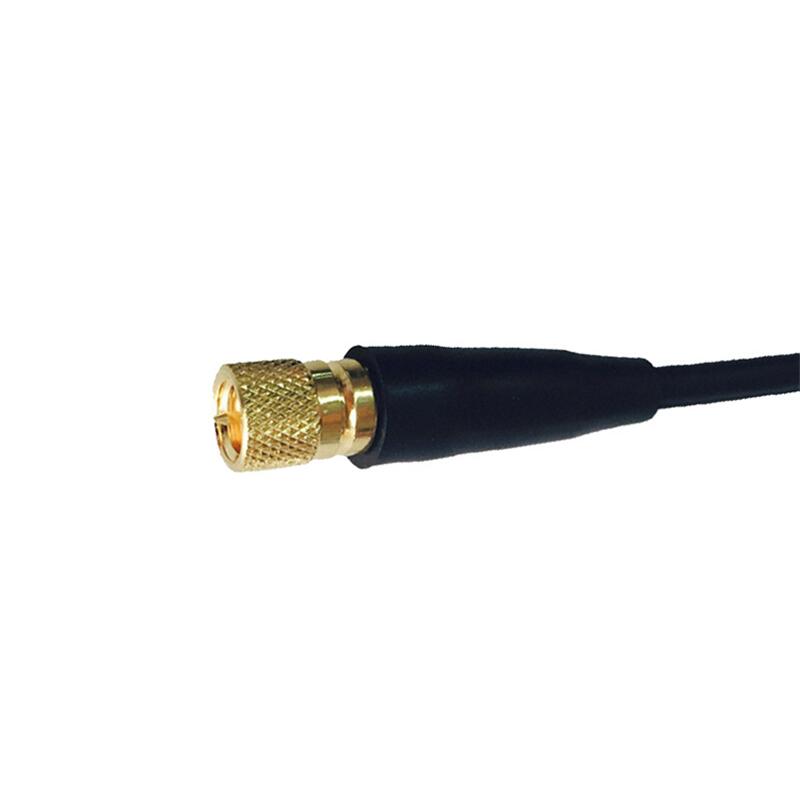
1. Understand Your Frequency Range
RF cable assemblies are designed to operate within specific frequency ranges. Frequency compatibility is the first factor to evaluate:
- Low-frequency applications (e.g., audio equipment, CB radios): RG-58 or RG-174 cables (0–1 GHz) are cost-effective choices.
- High-frequency systems (e.g., 5G, radar, satellite communications): Opt for low-loss cables like LMR-400 or Heliax (up to 18 GHz or higher).
- Ultra-high-frequency (UHF) applications: Use phase-stable cables with minimal signal attenuation.
Pro Tip: Always choose a cable rated for a frequency range higher than your maximum operating frequency to account for unexpected spikes.
2. Match the Impedance
Impedance mismatches can lead to signal reflections, degraded performance, and even equipment damage. Most RF systems use 50-ohm impedance (common in telecom and aerospace) or 75-ohm impedance (typical in video broadcasting).
- Verify your system’s impedance requirement (check device specifications or consult the manufacturer).
- Ensure connectors (e.g., SMA, BNC, N-type) match the cable’s impedance.
3. Evaluate Insertion Loss and VSWR
Two critical performance metrics for RF cables are insertion loss (signal loss over length) and Voltage Standing Wave Ratio (VSWR) (measure of signal reflection):
- Insertion loss: Lower loss is better, especially for long cable runs. Loss increases with frequency and cable length.
- VSWR: Aim for a ratio close to 1:1 (e.g., 1.2:1 or lower). Higher ratios indicate poor impedance matching.
Material matters: Cables with foam polyethylene insulation or air-spaced designs typically offer lower loss than solid dielectric cables.
4. Choose the Right Connector Type
Connectors must be compatible with your equipment and environment:
- SMA: Compact, ideal for high-frequency applications up to 18 GHz.
- BNC: Quick-connect, suitable for test equipment and lower frequencies (up to 4 GHz).
- N-type: Rugged, weatherproof option for outdoor or industrial use (up to 11 GHz).
- SMP/SMB: Miniature connectors for space-constrained applications.
Durability: For harsh environments, select connectors with gold plating (corrosion-resistant) or stainless-steel housings.
5. Consider Cable Length and Flexibility
- Length: Longer cables increase insertion loss. Use the shortest length possible for your setup.
- Flexibility: Semi-rigid cables offer superior shielding but lack bendability. For tight spaces, choose flexible or ultra-flexible coaxial cables (e.g., LMR-200).
6. Assess Environmental Conditions
Environmental factors can degrade performance:
- Temperature: Extreme heat or cold affects material stability. Silicone-jacketed cables handle -65°C to +200°C.
- Moisture/chemical exposure: Use cables with PTFE (Teflon) jackets or IP67-rated connectors.
- EMI/RFI interference: Double-shielded or braided cables provide better noise rejection.
7. Prioritize Quality and Compliance
- Certifications: Look for MIL-SPEC, RoHS, or REACH compliance for reliability and safety.
- Manufacturer reputation: Choose suppliers with proven expertise in RF technology (e.g., Times Microwave, Huber+Suhner).
- Testing: Request test reports for insertion loss, VSWR, and phase stability.
8. Balance Cost and Performance
While high-performance cables like phase-stable or ultra-low-loss variants are expensive, they’re essential for mission-critical applications. For less demanding uses (e.g., short-range Wi-Fi), budget-friendly RG cables may suffice.
Final Checklist for RF Cable Assembly Selection
Compliance with industry standards.
Frequency range and bandwidth requirements.
Impedance (50Ω vs. 75Ω).
Insertion loss and VSWR limits.
Connector type and durability.
Environmental resilience.
Hydrogen Projects Demand Eco-Cables: A Sustainable Shift in Energy Infrastructure
Introduction
As the global push for clean energy intensifies, hydrogen projects are emerging as a cornerstone of decarbonization strategies. However, these initiatives face a critical challenge: ensuring their infrastructure aligns with sustainability goals. Enter eco-cables—a revolutionary solution designed to meet the unique demands of hydrogen production, storage, and distribution. This article explores why eco-cables are indispensable for hydrogen projects, their benefits, and how they’re shaping the future of green energy.
1. The Rise of Hydrogen Projects: A Green Energy Revolution
Hydrogen, particularly green hydrogen (produced using renewable energy), is hailed as a game-changer for industries like transportation, manufacturing, and power generation. Governments and corporations worldwide are investing billions:
- The EU aims to produce 10 million tonnes of green hydrogen annually by 2030.
- Australia’s “Hydrogen Headstart” program targets large-scale export projects.
- The U.S. Inflation Reduction Act includes $9.5 billion for clean hydrogen initiatives.
However, hydrogen’s volatility and the need for extreme temperature/pressure resistance in infrastructure demand specialized components—starting with eco-cables.
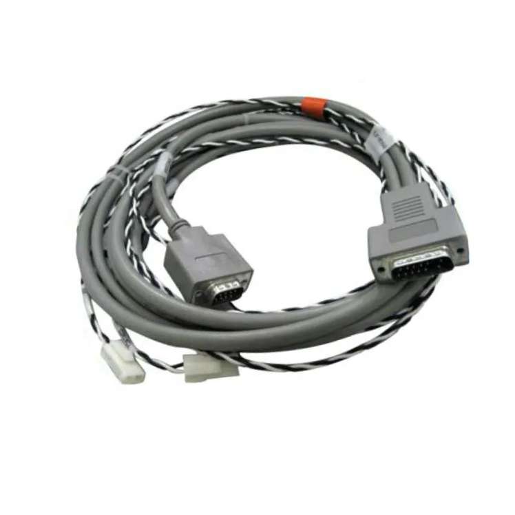
2. What Are Eco-Cables?
Eco-cables are advanced electrical cables engineered for sustainability and performance. Key features include:
- Low Environmental Impact: Made from recyclable, halogen-free materials to reduce toxic emissions.
- Durability: Resistant to extreme temperatures, corrosion, and mechanical stress.
- Energy Efficiency: Optimized conductivity to minimize power loss.
- Safety Compliance: Meet strict fire safety standards (e.g., IEC 60332) critical for hydrogen facilities.
3. Why Hydrogen Projects Need Eco-Cables
a. Safety in High-Risk Environments
Hydrogen is highly flammable, requiring infrastructure that prevents leaks and fires. Eco-cables with flame-retardant coatings and self-extinguishing properties mitigate risks in electrolyzers, pipelines, and storage tanks.
b. Corrosion Resistance
Hydrogen can cause “embrittlement,” weakening metal components. Eco-cables use polymeric insulation (e.g., cross-linked polyethylene) to withstand harsh chemical exposure.
c. Longevity in Extreme Conditions
From sub-zero storage temperatures to high-heat electrolysis, eco-cables maintain performance where traditional cables fail. For example, Norway’s H2M Maritime project uses subsea eco-cables rated for -40°C.
d. Regulatory Compliance
Governments are tightening sustainability mandates. The EU’s Corporate Sustainability Reporting Directive (CSRD) requires companies to disclose environmental impacts, making eco-cables essential for ESG compliance.
4. Real-World Applications of Eco-Cables in Hydrogen Projects
- Germany’s Energiepark Mainz: This green hydrogen plant utilizes eco-cables to connect wind turbines to electrolyzers, reducing CO2 emissions by 12,000 tonnes annually.
- Japan’s Hydrogen Highway: Toyota’s hydrogen refueling stations rely on eco-cables for safe, efficient power transmission.
- Chile’s Haru Oni Project: Eco-cables link wind farms to hydrogen production units in Patagonia’s harsh climate.
5. How to Choose the Right Eco-Cable for Hydrogen Projects
When selecting eco-cables, consider:
- Material Composition: Prioritize halogen-free, recyclable polymers.
- Certifications: Look for IEC, UL, or TÜV certifications for hydrogen compatibility.
- Temperature Range: Ensure cables can operate in -50°C to 120°C environments.
- Supplier Expertise: Partner with vendors experienced in renewable energy projects (e.g., Nexans, Prysmian Group).
6. The Future: Eco-Cables and the Hydrogen Economy
The global hydrogen infrastructure market is projected to reach **$1.4 trillion by 2030** (McKinsey). Eco-cables will play a pivotal role in this growth, driven by:
- Innovations: Bio-based insulation materials and AI-driven cable health monitoring.
- Cost Reductions: Economies of scale as hydrogen projects expand.
- Policy Support: Tax incentives for sustainable infrastructure under initiatives like the U.S. Bipartisan Infrastructure Law.
Standard Requirements for Domestic Cable Assemblies in China
If you’re sourcing, manufacturing, or using cable assemblies in China, understanding the country’s regulatory and quality standards is crucial. This guide breaks down the key requirements for domestic cable assemblies in China, helping businesses and consumers ensure compliance, safety, and reliability.
Why Standards Matter for Cable Assemblies in China
China is a global leader in electronics manufacturing, and its cable assembly industry is no exception. With rapid technological advancements and a focus on quality control, the Chinese government has established strict standards to:
- Ensure product safety for end-users.
- Promote fair competition among manufacturers.
- Align with international practices for export-oriented products.
Non-compliance can lead to legal penalties, product recalls, or reputational damage. Let’s explore the core standards you need to know.
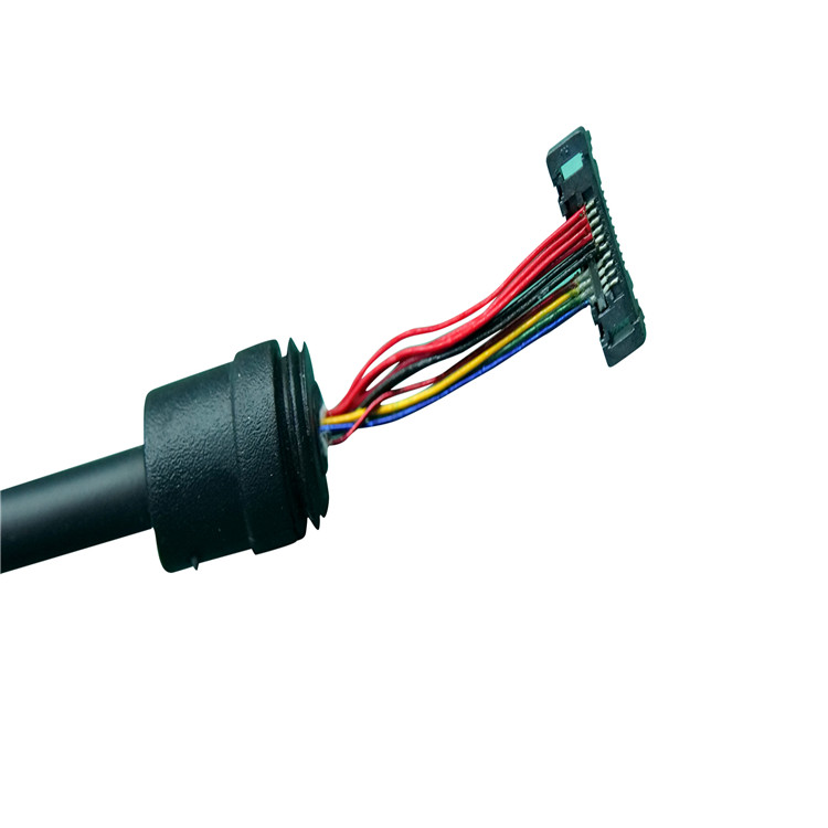
Key Standards for Domestic Cable Assemblies in China
1. GB/T Standards (National Standards)
China’s GB/T (Guobiao Recommended Standards) are foundational for cable assemblies. Relevant GB/T standards include:
- GB/T 5023: Specifies requirements for PVC-insulated cables.
- GB/T 12706: Covers power cables with extruded insulation.
- GB/T 19666: Focuses on flame-retardant and fire-resistant cables.
These standards define parameters like conductor materials, insulation thickness, voltage ratings, and temperature resistance.
2. CCC Certification (China Compulsory Certification)
The CCC mark is mandatory for many cable products sold in China. It ensures compliance with safety, electromagnetic compatibility (EMC), and environmental regulations. Products without CCC certification cannot legally enter the Chinese market.
3. RoHS Compliance
While not exclusive to cables, China’s RoHS regulations restrict hazardous substances (e.g., lead, mercury) in electronic components. This applies to both domestic and imported products.
4. Industry-Specific Standards
Depending on the application, additional standards may apply:
- Automotive cables: Follow QC/T 1037 for durability and performance.
- Data/communication cables: Meet YD/T 1019 for signal integrity.
How to Ensure Compliance
- Work with Certified Suppliers
Partner with manufacturers that provide valid CCC certificates and test reports. Verify their certifications through China’s Certification and Accreditation Administration (CNCA). - Conduct Third-Party Testing
Independent labs like SGS or TÜV Rheinland can test products against GB/T standards, ensuring they meet safety and performance criteria. - Maintain Documentation
Keep records of compliance certificates, test results, and material safety data sheets (MSDS) for audits. - Stay Updated
Standards evolve! Monitor updates from agencies like the Standardization Administration of China (SAC).
Common Challenges and Solutions
- Complex Regulations: China’s standards can overlap or differ from international norms (e.g., IEC or UL).
Solution: Hire local experts or consultants to navigate requirements. - High Testing Costs: CCC certification and testing can be expensive for small businesses.
Solution: Negotiate testing costs with suppliers or seek government subsidies for SMEs. - Counterfeit Products: Fake CCC marks are a risk in unregulated markets.
Solution: Buy from reputable suppliers and verify certifications directly.
Snake Tray – Cable Management & Industrial Cable Assemblies
In large-scale infrastructure projects—particularly in transportation, tunnel systems, and railway applications—the integrity of electrical infrastructure is non-negotiable. Snake Trayspecializes in delivering robust industrial cable assembliesand cable management solutions engineered to withstand the most challenging environments. Our mission is simple: to ensure reliable signal and power transmission through precision-manufactured components that guarantee rapid installation and long-term operational stability.
This article explores how our custom cable tray systems and pre-fabricated assemblies provide a competitive advantage for contractors, engineers, and procurement managers operating in high-stakes industrial sectors.
The Critical Role of Industrial Cable Assemblies in Heavy Infrastructure
When dealing with mission-critical systems like subway signaling, railway traction power, or tunnel ventilation controls, generic wiring solutions are insufficient. These environments demand industrial cable assembliesthat are not only durable but also designed for seamless integration.
Unlike standard off-the-shelf cables, industrial-grade assemblies are built to resist:
- •Extreme temperature fluctuations common in outdoor rail yards.
- •Constant vibration from passing trains or heavy machinery.
- •Corrosive elements such as moisture, chemicals, and salt spray in tunnels or coastal areas.
At Snake Tray, we manufacture assemblies that meet stringent industry standards (including NEC, IEC, and EN specifications). By utilizing high-quality conductors, abrasion-resistant jackets, and precision-engineered connectors, we ensure that every assembly delivers consistent performance under pressure.
Why Choose Snake Tray for Cable Management Solutions?
The term “cable management” often implies basic organization. At Snake Tray, we redefine it as a strategic component of your project’s success. Our solutions are specifically designed for the complexities of transportation and industrial applications.
1. Engineered for Harsh Environments
Our cable trays and industrial cable assembliesare tested against real-world stressors. Whether it’s the mechanical impact resistance required in a busy rail maintenance shed or the fire-retardant properties needed in an underground tunnel, our products are specified to perform when failure is not an option.
2. Customization at Scale
No two projects are identical. That is why we offer fully customized cable tray configurations and assembly lengths. We work directly with your engineering team to produce:
- •Pre-cut and pre-drilled cable trays.
- •Pre-wired harnesses with labeled terminations.
- •Assemblies with specific bend radii and connector types.
This level of customization eliminates on-site fabrication errors and reduces the need for specialized labor.
3. Material Versatility
We provide solutions in various materials to match environmental demands:
- •Hot-Dipped Galvanized Steel:For maximum corrosion resistance outdoors.
- •Stainless Steel (304/316):For wash-down areas or extreme chemical exposure.
- •Aluminum:For lightweight applications without compromising strength.
- •Fiberglass Reinforced Polymer (FRP):For non-conductive and non-sparking requirements.
Applications in Transportation, Tunnels, and Railways
The transportation sector relies heavily on uninterrupted power and data flow. Below is how our industrial cable assembliesand Snake Tray systems excel in specific scenarios:
Railway Electrification & Signaling
Railway systems require precise voltage delivery to overhead catenary systems and traction substations. Our heavy-duty cable assemblies ensure minimal voltage drop over long distances. Furthermore, our tray systems securely route these high-voltage lines away from sensitive signaling cables, preventing electromagnetic interference (EMI).
Tunnel Infrastructure
Tunnels present unique challenges: limited space, high humidity, and strict fire safety codes. Snake Tray provides low-profile cable trays that maximize vertical clearance while supporting complex bundles of power, lighting, and communication cables. Our industrial cable assembliesused here are often jacketed with low-smoke zero-halogen (LSZH) materials to protect passengers and personnel during emergencies.
Mass Transit & Depots
In metro stations and bus depots, the speed of installation is crucial to minimize service disruption. Using our prefabricated industrial cable assemblies, installation teams can connect entire sections of power distribution without extensive on-site termination. This results in faster project completion and reduced labor costs.
The Competitive Advantage of Custom Cable Tray Systems
One of the biggest inefficiencies in industrial construction is the time spent cutting, welding, and assembling cable supports on-site. Snake Tray eliminates this waste through our custom fabrication services.
By leveraging advanced manufacturing technology, we deliver:
- •Exact Fit:Trays manufactured to your exact project dimensions.
- •Faster Installation:Components arrive ready to mount, drastically reducing installation time.
- •Reduced Errors:Factory-controlled processes ensure consistency and eliminate measurement mistakes common in field work.
Pairing these custom trays with our purpose-built industrial cable assembliescreates a cohesive system where the cable and its support structure work in perfect harmony. This synergy enhances airflow around cables (reducing heat buildup) and simplifies future maintenance.
Ensuring Reliable Signal & Power Transmission
A weak link in any cable assembly can lead to catastrophic signal degradation or power loss. We address this through rigorous quality control:
- 1.Precision Crimping:Every connection point is crimped to manufacturer specifications using calibrated tools, ensuring optimal conductivity and tensile strength.
- 2.Comprehensive Testing:Before shipping, all industrial cable assembliesundergo continuity testing, insulation resistance testing, and sometimes high-potential (Hi-Pot) testing to verify dielectric strength.
- 3.Secure Termination:We use only industrial-grade connectors from trusted brands, ensuring compatibility and longevity even in high-vibration environments.
For sensitive data and signaling applications, we also offer shielded industrial cable assembliesthat protect against EMI and radio frequency interference (RFI), which are critical in densely wired transit hubs.
Streamlining Your Procurement Process
We understand that B2B buyers value reliability and transparency. Partnering with Snake Tray means more than just purchasing a product; it means engaging with a technical partner who understands your supply chain needs.
- •Detailed Documentation:We provide full cut sheets, test reports, and certification documents with every order.
- •Scalable Production:From pilot programs to city-wide transit expansions, our production capacity scales with your project demands.
- •Global Logistics:We have experience shipping large industrial orders worldwide, ensuring your industrial cable assembliesand trays arrive on schedule and in spec.
Conclusion: Build with Confidence
In industries where safety, uptime, and efficiency are paramount, specifying the right components is critical. Snake Traycombines innovative cable management design with the manufacturing excellence of high-performance industrial cable assemblies.
From the initial design phase to final installation, our solutions are built to reduce complexity, accelerate deployment, and ensure the reliable transmission of power and signals across your entire infrastructure.
If you are looking for a proven partner for your next transportation, tunnel, or railway project, contact the experts at Snake Tray today. Let us help you build a system that lasts.
Contact us for a custom quote on your next industrial project.
High-Temp Cable Breakthrough Boosts Safety
In industries where extreme heat is a constant challenge—from manufacturing plants to renewable energy systems—cable failures can lead to catastrophic consequences. A groundbreaking advancement in high-temperature (high-temp) cable technology is now revolutionizing safety standards, offering unprecedented durability and reliability. This article explores how this innovation works, its real-world applications, and why it matters for businesses prioritizing safety and efficiency.
The Problem with Traditional Cables in High-Heat Environments
Standard cables are prone to degradation when exposed to temperatures exceeding 150°C (302°F). Over time, insulation can crack, conductors may oxidize, and short circuits or fires can occur. Industries like steel production, automotive manufacturing, and power generation have long struggled with frequent cable replacements, downtime, and safety risks.
The Breakthrough: Next-Gen High-Temp Cable Technology
Recent advancements in materials science and engineering have led to cables capable of withstanding temperatures up to 1,000°C (1,832°F) without compromising performance. Key innovations include:
- Advanced Insulation Materials
- Ceramic-based coatings: Provide exceptional thermal resistance and prevent electrical leakage.
- Polymer nanocomposites: Enhance flexibility while resisting heat-induced brittleness.
- Reinforced Conductors
- Silver-plated or nickel-alloy conductors reduce oxidation, ensuring stable conductivity even under extreme conditions.
- Multi-Layered Shielding
- Protects against electromagnetic interference (EMI) and mechanical stress, critical for precision-driven industries like aerospace.
This technology not only extends cable lifespan by 300–500% but also meets stringent international safety certifications (e.g., UL, IEC).
Industries Benefiting from High-Temp Cables
- Energy & Utilities
- Solar farms and nuclear plants use high-temp cables in turbine systems and reactors to prevent meltdown risks.
- Automotive & EV Manufacturing
- Electric vehicle (EV) battery systems and charging stations rely on heat-resistant wiring to avoid thermal runaway incidents.
- Industrial Manufacturing
- Foundries, glass factories, and chemical plants deploy these cables in furnaces and high-heat machinery.
- Aerospace
- Withstand extreme temperatures in jet engines and spacecraft components.
Safety Advantages You Can’t Ignore
- Fire Prevention: Non-flammable materials reduce the risk of ignition in volatile environments.
- Reduced Maintenance: Fewer replacements mean lower costs and minimized worker exposure to hazardous areas.
- Compliance: Aligns with OSHA, NFPA 70, and other safety regulations.
How to Choose the Right High-Temp Cable
When selecting cables for high-heat applications, consider:
- Temperature Rating: Match the cable’s max temperature to your operational needs.
- Chemical Resistance: Ensure compatibility with oils, acids, or solvents in your facility.
- Flexibility: Opt for cables that maintain pliability in tight spaces.
- Certifications: Look for UL, RoHS, or MIL-SPEC approvals.
The Future of High-Temp Cable Technology
Researchers are integrating smart sensors into cables to monitor real-time temperature, wear, and electrical load. Additionally, sustainable materials like bio-based polymers are emerging, reducing environmental impact without sacrificing performance.
What are the types of industrial cable connectors
Industrial cable connectors are essential components in various industrial systems, enabling the reliable transmission of power, signals, and data. There are several common types, each designed to meet specific application requirements.
Circular connectors are widely used in industrial environments. Their circular shape provides a robust and secure connection, making them resistant to vibration, moisture, and dust. They are commonly found in machinery, robotics, and aerospace applications. For example, in factory automation, circular connectors ensure stable power and signal transmission between robotic arms and control systems.
Rectangular connectors are another popular type. They offer a high density of contacts, allowing for the connection of multiple wires in a compact space. This makes them suitable for use in control panels, where space is often limited. Rectangular connectors also provide good electrical performance, ensuring efficient signal transmission.
Coaxial connectors are designed for high-frequency applications. They consist of an inner conductor, an outer conductor, and a dielectric material between them. This structure helps to minimize signal loss and interference, making coaxial connectors ideal for use in telecommunications,and radar systems.
Fiber optic connectors are used to connect optical fibers. They ensure precise alignment of the fibers to minimize light loss. Fiber optic connectors are widely used in data communication systems, where high-speed and long-distance transmission is required. They offer several advantages over traditional electrical connectors, including higher bandwidth, lower signal loss, and immunity to electromagnetic interference.
**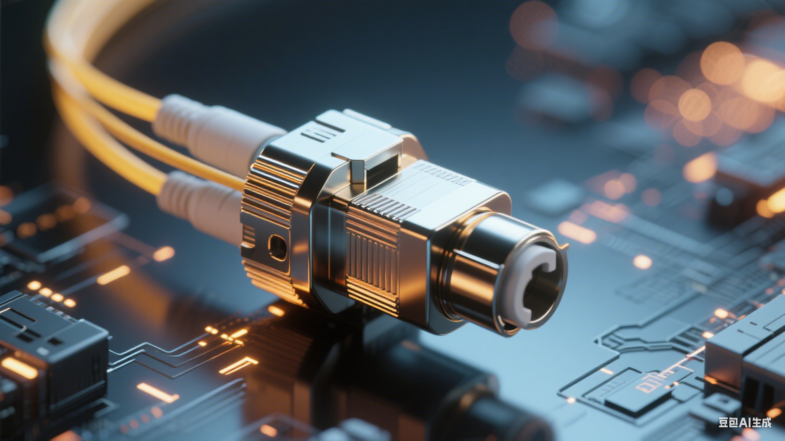
(Note: This is a placeholder for a 500*500px image of industrial cable)
When it comes to industrial cable connectors, FRS brand factory is a trusted choice. With years of experience in the industry, FRS produces high-quality connectors that meet the strictest standards. Whether you need circular, rectangular, coaxial, or fiber optic connectors, FRS has a wide range of products to meet your specific needs. Choose FRS for reliable and efficient industrial cable connections.
Extreme Weather Tests Outdoor Cables
As climate change accelerates, outdoor cables face unprecedented challenges from extreme weather conditions. From scorching heatwaves to bone-chilling freezes, these environmental stressors can significantly impact cable performance and lifespan, leading to potential disruptions in power and communication networks.
In regions experiencing intense heatwaves, outdoor cables are subjected to elevated temperatures that can cause the insulation materials to degrade. Polyvinyl chloride (PVC), a commonly used insulation material, becomes more flexible and prone to cracking as it softens under high heat. This cracking exposes the inner conductors, increasing the risk of short circuits and electrical failures. For instance, during the record-breaking heatwave in California in 2023, numerous power outages were attributed to damaged outdoor cables. The continuous exposure to temperatures exceeding 40°C (104°F) for extended periods weakened the cable insulation, ultimately leading to system breakdowns.
Conversely, extremely cold weather poses its own set of problems. When temperatures plummet, insulation materials become brittle and more likely to fracture. This is especially true for rubber-based insulations, which lose their elasticity in freezing conditions. In areas with harsh winters, such as the northern parts of Canada and Russia, ice accumulation on cables can add significant weight, causing them to sag or even break. The mechanical stress from the ice and snow, combined with the brittleness of the insulation, creates a perfect storm for cable failure. A case in point is the winter storms in Texas in 2021, where the freezing temperatures and heavy ice caused widespread damage to outdoor power cables, leaving millions without electricity.
High winds and storms also take a toll on outdoor cables. Strong gusts can whip cables around, causing abrasion against supports or other objects. Over time, this abrasion wears away the insulation, exposing the conductors. Additionally, lightning strikes during thunderstorms can induce high-voltage surges in cables, damaging the internal components and potentially rendering the cables inoperable. In coastal regions prone to hurricanes and typhoons, the combination of high winds, saltwater spray, and heavy rain can further accelerate the deterioration of outdoor cables. The salt in the spray can corrode metal components, while the rain can seep into any existing cracks in the insulation, leading to short circuits.
Wildfires are another emerging threat to outdoor cables, particularly in fire-prone areas. The intense heat and flames from wildfires can quickly melt and destroy cables, disrupting power and communication lines that are crucial for emergency response and recovery efforts. The Camp Fire in California in 2018, one of the most destructive wildfires in the state’s history, burned through miles of outdoor cables, leaving entire communities isolated without essential services.
The impact of extreme weather on outdoor cables extends beyond immediate failures. Frequent exposure to harsh conditions can shorten the expected lifespan of cables, requiring more frequent replacements and maintenance. This not only incurs additional costs for utility companies and network operators but also poses challenges in ensuring a reliable supply of power and connectivity to consumers.
To mitigate these risks, the development of more resilient outdoor cable materials is crucial. Researchers are exploring new insulation materials with enhanced heat resistance, cold flexibility, and durability. Some innovative materials are designed to self-heal minor cracks or resist abrasion better, offering improved protection against extreme weather. Additionally, better installation practices, such as proper routing to avoid areas prone to ice accumulation or abrasion, and the use of protective covers and conduits, can help extend the lifespan of outdoor cables in harsh environments.
In conclusion, extreme weather events are increasingly putting outdoor cables to the test. Understanding the vulnerabilities of cables in different weather conditions is the first step in developing strategies to safeguard critical infrastructure and maintain reliable power and communication networks in the face of a changing climate.
high temperature cable connectors
In industries where extreme heat is a constant challenge—such as manufacturing, energy, aerospace, and automotive—reliable electrical connectivity is non-negotiable. High temperature cable connectors stand as critical components that ensure seamless power and signal transmission even in harsh thermal environments. Unlike standard connectors, these specialized devices are engineered to withstand elevated temperatures without compromising performance, safety, or durability, making them indispensable for applications where failure could lead to costly downtime or safety hazards.
Key Characteristics of High Temperature Cable Connectors
The functionality of high temperature cable connectors hinges on several core design and material features, each tailored to combat the effects of extreme heat:
- Heat-Resistant Materials: The housing and contact materials are the first line of defense against high temperatures. Common materials include ceramic, high-grade thermoplastics (such as PEEK and PPS), and metal alloys like stainless steel or nickel-plated brass. Ceramic connectors excel in ultra-high temperature scenarios (up to 1000°C), while PEEK-based connectors offer a balance of heat resistance (up to 260°C) and mechanical strength. Metal alloys provide robustness and thermal conductivity, ensuring contacts remain stable under heat stress.
- Thermal Stability: These connectors are designed to maintain consistent electrical resistance and mechanical integrity across wide temperature ranges. They undergo rigorous testing to ensure no deformation, melting, or degradation when exposed to prolonged heat or thermal cycling (rapid temperature fluctuations). This stability prevents signal loss, short circuits, or physical damage that could disrupt operations.
- Sealing and Protection: Many high temperature applications also involve moisture, dust, or chemicals. As a result, these connectors often feature IP-rated sealing (e.g., IP67 or IP68) or hermetic sealing to prevent contaminants from entering the connection point. This dual protection—against heat and environmental factors—extends their lifespan in harsh conditions.
- Current-Carrying Capacity: High temperature environments can reduce the current-carrying capacity of standard connectors due to increased resistance. High temperature variants are engineered to handle specified current loads without overheating, thanks to optimized contact designs and heat-dissipating materials.
Main Application Areas
The versatility of high temperature cable connectors makes them essential in numerous high-heat industries:
- Industrial Manufacturing: In sectors like metalworking (forging, casting), glass production, and plastic molding, where equipment operates at temperatures exceeding 300°C, these connectors power sensors, heating elements, and control systems. They ensure continuous data transmission for process monitoring and automation.
- Energy Sector: Oil and gas drilling (downhole equipment exposed to high temperatures and pressure), solar thermal power plants (concentrated heat zones), and nuclear power facilities rely on high temperature connectors for safe and reliable energy transfer. Their resistance to heat and corrosion is critical in these high-risk environments.
- Aerospace and Defense: Aircraft engines, spacecraft thermal control systems, and military vehicles operate in extreme temperature ranges (from -55°C to 500°C). High temperature connectors ensure communication, navigation, and power systems function flawlessly during flight or mission operations.
- Automotive Industry: Modern electric vehicles (EVs) and hybrid vehicles have high-temperature components like battery packs, inverters, and motors. High temperature connectors facilitate efficient power distribution between these components, withstanding the heat generated during charging and operation.
Selection Tips for High Temperature Cable Connectors
Choosing the right high temperature cable connector requires careful consideration of application-specific factors:
- Environmental Temperature Range: First, determine the maximum and minimum temperatures the connector will encounter. Ensure the connector’s rated temperature exceeds the application’s peak heat to avoid premature failure.
- Connection Type and Specifications: Match the connector’s pin count, voltage rating, and current capacity to the requirements of the equipment. Consider factors like plug-and-play convenience or the need for locking mechanisms to prevent accidental disconnection.
- Material Compatibility: If the connector will be exposed to chemicals, oils, or fuels, select materials that resist corrosion or degradation. For example, stainless steel is ideal for corrosive industrial environments, while ceramic is better for ultra-high heat without chemical exposure.
- Certifications and Compliance: Look for connectors certified by industry standards (e.g., UL, IEC, MIL-STD) to ensure they meet safety and performance benchmarks. This is particularly important in regulated sectors like aerospace and energy.
Choose FRS for Reliable High Temperature Cable Connectors
When it comes to high temperature cable connectors that deliver consistent performance in the harshest conditions, FRS brand factory stands out as a trusted partner. With years of expertise in engineering and manufacturing specialized electrical components, FRS prioritizes quality, durability, and precision in every connector. Our high temperature cable connectors are crafted from premium materials, rigorously tested to withstand extreme heat and environmental stress, and tailored to meet the unique needs of industries ranging from automotive to aerospace. Whether you require standard configurations or custom solutions, FRS ensures on-time delivery, competitive pricing, and dedicated technical support to keep your operations running smoothly. Choose FRS for connectors that don’t just meet expectations—they exceed them.
What Are the Features of Sensor Cable Assemblies
Sensor cable assemblies are critical components that connect sensors to data acquisition systems, control units, or other electronic devices. Their performance directly impacts the accuracy, reliability, and longevity of the entire sensing system. For users seeking to understand these components, grasping their core features is essential for making informed purchasing and application decisions.
1. High-Precision Signal Transmission
One of the most prominent features of sensor cable assemblies is their ability to ensure high-precision signal transmission. Sensors often generate weak electrical signals, and any interference during transmission can distort the data, leading to inaccurate readings. To address this, these cable assemblies are equipped with advanced shielding technologies, such as twisted-pair conductors, foil shielding, and braided shielding. Twisted-pair conductors reduce electromagnetic interference (EMI) by canceling out external magnetic fields, while foil and braided shielding provide a physical barrier against radio frequency interference (RFI). This multi-layered shielding design ensures that the original sensor signals are transmitted to the receiving end with minimal loss or distortion, maintaining the integrity of the measurement data.
2. Excellent Environmental Adaptability
Sensor cable assemblies are frequently used in harsh operating environments, so strong environmental adaptability is a key feature. They are designed to withstand a wide range of temperatures, typically from -40°C to 125°C or even higher for specialized models, making them suitable for both extreme cold and high-temperature applications like industrial ovens or outdoor monitoring systems. Additionally, the outer jackets of the cables are made from durable materials such as PVC, PUR (polyurethane), or PTFE (polytetrafluoroethylene). PVC offers good flexibility and cost-effectiveness for general environments, while PUR is resistant to oil, abrasion, and chemicals, making it ideal for industrial settings with frequent mechanical contact or exposure to lubricants. PTFE, on the other hand, provides excellent resistance to high temperatures and corrosive substances, suitable for aerospace or chemical processing industries.
3. Mechanical Durability and Flexibility
Mechanical durability is another essential feature of sensor cable assemblies. In many applications, such as robotics, automated production lines, or medical equipment, the cables are subject to repeated bending, twisting, and pulling. To withstand these mechanical stresses, the cables are constructed with reinforced conductors and flexible insulation materials. The conductors are usually made of high-quality copper, which not only ensures good electrical conductivity but also has sufficient tensile strength. Some cables also feature a stranding structure that enhances flexibility, allowing them to bend repeatedly without breaking. Moreover, the outer jacket materials are chosen for their abrasion resistance, preventing damage from friction with other components or surfaces in the operating environment.
4. Customizable Configurations
Sensor applications vary widely across different industries, so sensor cable assemblies offer highly customizable configurations to meet specific requirements. This customization includes cable length, conductor gauge, connector type, shielding method, and jacket material. For example, in a medical device application, a short-length cable with a miniature connector and biocompatible jacket may be needed, while in a large-scale industrial plant, a long-length cable with a heavy-duty connector and high-temperature shielding may be required. Manufacturers can tailor these components to match the exact needs of the application, ensuring optimal performance and easy integration into the existing system.
5. Compliance with Industry Standards
Reliable sensor cable assemblies comply with various international and industry-specific standards to ensure safety and performance. These standards include IEC (International Electrotechnical Commission), UL (Underwriters Laboratories), and CE (Conformité Européenne) certifications. Compliance with these standards guarantees that the cables meet strict requirements for electrical safety, fire resistance, and environmental performance. For instance, UL certification ensures that the cables are safe for use in electrical systems, while CE marking indicates that the product meets the health, safety, and environmental protection standards of the European Union. This compliance gives users confidence in the quality and reliability of the cable assemblies.
Choose FRS for High-Quality Sensor Cable Assemblies
When it comes to sensor cable assemblies that embody all these outstanding features, FRS brand factory stands out as a trusted partner. With years of experience in the field, FRS is dedicated to manufacturing sensor cable assemblies that prioritize precision, durability, and customization. Our products adopt advanced shielding technologies and high-quality materials to ensure stable signal transmission and excellent environmental adaptability, meeting the diverse needs of industries such as industrial automation, medical equipment, and automotive electronics. Whether you require standard configurations or custom solutions, FRS has the expertise and capabilities to deliver reliable products that enhance the performance of your sensing systems. Choose FRS, and experience the difference that professional sensor cable assemblies can make.
Climate-Proof Cables Gain Priority
As global temperatures rise and extreme weather events become more frequent, industries worldwide are rethinking infrastructure design to withstand environmental challenges. Among these innovations, climate-proof cables are emerging as a critical component in modern engineering, offering enhanced durability and reliability in harsh conditions.
What Are Climate-Proof Cables?
Climate-proof cables are specially designed electrical or communication cables engineered to resist damage from environmental stressors such as extreme temperatures, flooding, UV radiation, humidity, and chemical exposure. These cables utilize advanced materials like cross-linked polyethylene (XLPE), corrosion-resistant alloys, and protective sheathing to maintain functionality in volatile climates.

Why Climate Resilience Matters
According to the World Meteorological Organization (WMO), weather-related disasters have increased fivefold over the past 50 years, costing billions in damages annually. Traditional cables, vulnerable to degradation from moisture, heat, or physical stress, often fail during storms, wildfires, or floods, leading to power outages, communication breakdowns, and safety risks. Climate-proof cables address these vulnerabilities, ensuring uninterrupted energy transmission and data connectivity even in disaster scenarios.
Key Applications Driving Demand
- Renewable Energy Systems: Solar farms, wind turbines, and hydropower plants rely on cables that endure temperature fluctuations, saltwater corrosion (in offshore installations), and prolonged UV exposure.
- Urban Infrastructure: Cities in flood-prone or coastal regions are upgrading power grids and telecom networks with submersible, waterproof cables to prevent outages during heavy rains or storm surges.
- Transportation Networks: Railways, airports, and EV charging stations require heat-resistant and fire-retardant cables to operate safely in extreme conditions.
- Industrial Facilities: Oil refineries, chemical plants, and mining operations use cables resistant to abrasion, chemicals, and high temperatures.
Technological Innovations
Manufacturers are integrating cutting-edge features into climate-proof cables:
- Self-Healing Insulation: Materials that automatically repair minor cracks caused by thermal expansion.
- Smart Monitoring: Embedded sensors detect real-time changes in temperature, moisture, or mechanical stress, enabling predictive maintenance.
- Eco-Friendly Designs: Recyclable materials and low-smoke, zero-halogen (LSZH) sheathing reduce environmental impact during production and disposal.
Market Growth and Industry Standards
The global market for climate-resistant cables is projected to grow at a CAGR of 6.8% from 2023 to 2030, driven by stricter government regulations and infrastructure modernization initiatives. Organizations like the International Electrotechnical Commission (IEC) and Underwriters Laboratories (UL) have introduced certifications (e.g., UL 1277 for fire resistance) to standardize performance benchmarks.
The Path Forward
As climate change accelerates, the shift toward climate-proof cables reflects a broader commitment to future-proofing critical infrastructure. Investments in R&D, coupled with cross-industry collaboration, will further enhance cable durability, efficiency, and adaptability—ensuring energy and communication systems remain operational in an increasingly unpredictable world.
Industrial Cable for Aerospace
The aerospace industry stands as a pinnacle of technological precision, where every component plays a critical role in ensuring safety, reliability, and performance. Among these components, industrial cables are the unsung heroes that facilitate the seamless transmission of power, data, and signals across aircraft, spacecraft, and related systems. Unlike standard industrial cables, those designed for aerospace applications must meet extraordinarily stringent requirements to withstand the harshest operating environments and adhere to rigorous industry standards.
Key Requirements for Aerospace-Grade Industrial Cables
Aerospace environments are characterized by extreme conditions that demand cables with exceptional durability and functionality. One of the primary requirements is temperature resistance. Aerospace cables must operate reliably in a wide temperature range, from the frigid cold of high-altitude flight (as low as -65°C) to the intense heat generated by engine compartments or re-entry into the Earth’s atmosphere (exceeding 200°C). This necessitates the use of advanced insulation and jacketing materials that maintain their structural integrity and electrical properties under such extremes.
Another critical factor is weight reduction. In aerospace, every gram matters, as excess weight directly impacts fuel efficiency, payload capacity, and overall performance. Aerospace industrial cables are therefore engineered using lightweight materials, such as aluminum conductors instead of traditional copper (in specific low-power applications) and thin, high-strength insulation. This balance between weight and performance is a key differentiator from standard industrial cables.
Electromagnetic interference (EMI) shielding is also paramount. Modern aircraft and spacecraft are equipped with a multitude of electronic systems, from navigation and communication to avionics and control systems. Uncontrolled EMI can disrupt these systems, leading to critical failures. Aerospace cables feature robust EMI shielding, often using materials like braided copper or aluminum, to prevent signal interference and ensure clear, uninterrupted data and power transmission.
Additionally, mechanical durability cannot be overlooked. Aerospace cables are subjected to constant vibration, flexing, and exposure to harsh chemicals (such as jet fuel and hydraulic fluids) and environmental factors (like moisture and UV radiation). They must resist abrasion, cuts, and degradation to maintain performance throughout the lifespan of the aerospace vehicle, which can span decades.
Common Types and Applications of Aerospace Industrial Cables
Aerospace industrial cables come in various types, each tailored to specific applications within the aerospace ecosystem. Power cables are designed to transmit high levels of electrical power to critical systems, such as engines, landing gear, and environmental control units. These cables feature thick conductors and durable insulation to handle high current loads while withstanding temperature fluctuations.
Data and signal cables are essential for the transmission of sensitive information between avionics systems, flight control computers, and communication devices. These cables prioritize signal integrity, with twisted pairs or coaxial designs to minimize EMI and ensure accurate data transfer. They are used in applications such as GPS navigation, radar systems, and in-flight entertainment.
Thermocouple cables are specialized for temperature measurement in extreme environments, such as engine exhausts and combustion chambers. These cables are constructed using specific alloy combinations that generate a voltage proportional to temperature differences, enabling precise temperature monitoring critical for engine performance and safety.
High-temperature cables are used in areas with extreme heat, such as near engines or re-entry vehicles. They utilize advanced materials like ceramic fiber insulation or PEEK (polyetheretherketone) jacketing, which can withstand temperatures well above 300°C without degradation.
The Role of Quality Standards in Aerospace Cables
To ensure the reliability and safety of aerospace industrial cables, they must comply with strict industry standards. Organizations such as the Society of Automotive Engineers (SAE), the International Electrotechnical Commission (IEC), and the Federal Aviation Administration (FAA) set forth rigorous specifications for cable design, materials, testing, and performance. For example, SAE AS22759 outlines requirements for aerospace-grade insulated electric cables, covering aspects like conductor size, insulation thickness, temperature rating, and flame resistance.
Compliance with these standards involves extensive testing, including temperature cycling, flame resistance, EMI shielding effectiveness, mechanical flexing, and chemical resistance. Only cables that pass these rigorous tests are certified for use in aerospace applications, providing manufacturers and operators with the confidence that the cables will perform reliably under the most demanding conditions.
FRS: Your Trusted Partner for Aerospace-Grade Industrial Cables
When it comes to industrial cables for aerospace, precision, reliability, and compliance are non-negotiable. FRS brand factory understands the unique challenges of the aerospace industry and is committed to delivering high-quality, aerospace-grade cables that meet and exceed global standards. With years of expertise in materials science and cable engineering, FRS designs and manufactures cables tailored to the most demanding aerospace applications, from commercial aircraft to spacecraft and defense systems.
FRS cables are engineered using the latest lightweight, high-temperature, and EMI-shielding materials, ensuring optimal performance while reducing weight and enhancing safety. Each cable undergoes rigorous testing in state-of-the-art facilities to ensure compliance with SAE, IEC, and FAA standards, guaranteeing reliability in even the harshest environments. Whether you need power cables for aircraft engines, data cables for avionics systems, or high-temperature cables for space exploration, FRS has the solution to meet your aerospace needs. Choose FRS for aerospace industrial cables that power innovation and safety in the sky and beyond.
Zero-Waste Packaging for Cable Shipments: A Sustainable Approach
Introduction
The shipping industry faces growing pressure to reduce waste, and cable shipments are no exception. Traditional packaging methods often rely on plastic wraps, foam fillers, and non-recyclable materials that harm the environment. Switching to zero-waste packaging not only benefits the planet but also enhances brand reputation and cuts long-term costs.
Practical Zero-Waste Solutions
1. Recyclable Cardboard Spools
Replace plastic spools with sturdy, recycled cardboard alternatives. These are biodegradable, cost-effective, and widely accepted by recycling programs.
2. Biodegradable Void Fillers
Instead of plastic bubble wrap, use:
- Mushroom-based packaging
- Compostable paper padding
- Shredded recycled paper
3. Minimalist Design
Reduce excess packaging by:
- Using custom-sized boxes to avoid wasted space
- Eliminating unnecessary layers of protection
4. Reusable Shipping Containers
For bulk shipments, invest in durable, returnable containers made from metal or reinforced recycled plastic.
5. Supplier & Customer Education
Encourage eco-friendly practices by:
- Providing clear recycling instructions
- Partnering with green-certified logistics providers
Steel Plant Cuts Downtime with Custom Cables: A Cost-Saving Solution
Introduction
In heavy industries like steel manufacturing, unexpected downtime can cost thousands per minute. XYZ Steel Plant recently achieved a 37% reduction in production interruptions by implementing custom-engineered cables – a solution more manufacturers should consider.
The Challenge: Frequent Cable Failures
Traditional off-the-shelf cables failed every 6-8 weeks due to:
- Extreme heat near furnaces (reaching 150°C+)
- Mechanical stress from heavy equipment vibrations
- Chemical exposure to cooling agents
Custom Cable Solution
Working with ABC Cable Solutions, the plant developed cables featuring:
✔ High-temperature silicone insulation (withstands 200°C)
✔ Vibration-resistant strain relief boots
✔ Chemical-resistant PVC outer jackets
✔ Modular connectors for quick replacement
Measurable Results
MetricBeforeAfterImprovementAvg. downtime/month14.5 hrs9.1 hrs37% ↓Cable lifespan7 weeks22 weeks214% ↑Maintenance costs$18k/month$6.5k/month64% ↓
Implementation Tips
- Thermal Mapping: Identify hotspots needing special insulation
- Failure Analysis: Examine damaged cables for customization clues
- Supplier Collaboration: Work with manufacturers who provide:
- On-site assessments
- Rapid prototyping
- Lifetime performance guarantees
cable assemblies for automotive
In the complex and highly integrated world of modern automobiles, every component plays a critical role in ensuring performance, safety, and reliability. Among these essential components, automotive cable assemblies stand out as the “nervous system” of the vehicle, facilitating the seamless transmission of electrical signals, power, and data between various parts. From engine control units (ECUs) and infotainment systems to advanced driver-assistance systems (ADAS) and lighting, automotive cable assemblies are indispensable for the smooth operation of both traditional internal combustion engine (ICE) vehicles and the rapidly growing electric vehicle (EV) market. As automotive technology continues to evolve—with trends like electrification, autonomous driving, and connectivity driving innovation—the demand for high-quality, durable, and precision-engineered cable assemblies has never been higher.
The Critical Role of Cable Assemblies in Modern Automotive Systems
Automotive cable assemblies are more than just a collection of wires and connectors; they are custom-engineered solutions designed to withstand the harsh operating environments of vehicles. These environments include extreme temperatures (ranging from -40°C in cold climates to over 125°C under the hood), constant vibration, exposure to chemicals (such as oil, fuel, and coolant), and mechanical stress. Without robust cable assemblies, even the most advanced automotive systems would fail to function reliably, leading to performance issues, safety hazards, and costly downtime.
In traditional ICE vehicles, cable assemblies are responsible for transmitting power to the starter motor, delivering signals to the fuel injection system, and connecting the dashboard controls to various sensors. In EVs, their role becomes even more critical. EVs rely on high-voltage cable assemblies to transfer power from the battery pack to the electric motor, with voltage requirements often exceeding 400V (and up to 800V in newer models). These high-voltage cable assemblies must meet strict safety standards to prevent electrical arcing, overheating, and short circuits—factors that directly impact the vehicle’s safety and range. Additionally, EVs feature more complex electronic systems, including battery management systems (BMS), regenerative braking systems, and charging interfaces, all of which depend on precision cable assemblies for seamless communication and power distribution.
The rise of ADAS and autonomous driving has further elevated the importance of automotive cable assemblies. ADAS features such as adaptive cruise control, lane-keeping assist, and automatic emergency braking rely on a network of sensors (cameras, radar, LiDAR) that generate massive amounts of data. This data must be transmitted to the vehicle’s ECU in real time with minimal latency, requiring high-speed data cable assemblies that meet standards like Ethernet AVB (Audio Video Bridging) or CAN FD (Controller Area Network Flexible Data-Rate). Any delay or interference in data transmission could compromise the performance of these safety-critical systems, making high-quality cable assemblies a non-negotiable component in the development of autonomous vehicles.
Common Types of Automotive Cable Assemblies and Their Applications
Automotive cable assemblies come in a wide range of types, each designed to meet specific application requirements. Understanding the different types and their uses is essential for automotive manufacturers and suppliers looking to select the right solution for their vehicles.
1. Low-Voltage Cable Assemblies
Low-voltage (LV) cable assemblies are the most common type in vehicles, typically operating at 12V or 24V. They are used for powering and controlling non-critical systems such as interior lighting, power windows, door locks, infotainment systems, and HVAC (heating, ventilation, and air conditioning) units. LV cable assemblies are usually composed of copper wires (known for their excellent conductivity) insulated with materials like PVC (polyvinyl chloride) or XLPE (cross-linked polyethylene), which provide good flexibility and chemical resistance. They may also include shielding to reduce electromagnetic interference (EMI) from other electronic components, ensuring clear signal transmission for audio and navigation systems.
2. High-Voltage Cable Assemblies
As mentioned earlier, high-voltage (HV) cable assemblies are essential for EVs and hybrid electric vehicles (HEVs). They are designed to handle voltages between 400V and 800V and currents of several hundred amps. HV cable assemblies feature thicker conductors (often made of copper or aluminum) and robust insulation materials like EPDM (ethylene propylene diene monomer) or silicone rubber, which can withstand high temperatures and electrical stress. They also include specialized shielding (such as braided copper or aluminum foil) to prevent EMI and ensure the safety of nearby components and passengers. Additionally, HV cable assemblies are equipped with safety features like connectors with locking mechanisms and insulation monitoring systems to detect faults and prevent electric shock.
3. Data Cable Assemblies
Data cable assemblies are designed for the transmission of digital signals between sensors, ECUs, and other electronic devices. With the increasing complexity of automotive electronics, data cable assemblies must support higher data rates and be resistant to EMI. Common types of data cable assemblies used in automobiles include:
- CAN Bus Cable Assemblies: Used for connecting ECUs and sensors in a network, CAN bus (Controller Area Network) is a widely adopted standard in automotive applications. CAN FD (Flexible Data-Rate) cable assemblies offer higher bandwidth than traditional CAN, making them suitable for ADAS and EV systems.
- Ethernet Cable Assemblies: Automotive Ethernet is becoming increasingly popular for high-speed data transmission, especially in autonomous vehicles. Standards like IEEE 802.3bw (100BASE-T1) and IEEE 802.3by (1000BASE-T1) support data rates of 100Mbps and 1Gbps, respectively, enabling the transfer of large amounts of data from LiDAR and camera systems.
- LVDS Cable Assemblies: Low-Voltage Differential Signaling (LVDS) cable assemblies are used for transmitting video signals from cameras to the vehicle’s infotainment or ADAS display units. They provide high noise immunity and low power consumption, making them ideal for in-vehicle video applications.
4. Coaxial Cable Assemblies
Coaxial cable assemblies are used for transmitting high-frequency signals, such as those used in GPS navigation systems, satellite radio, and cellular connectivity (4G/5G). They consist of a central conductor, an insulating layer, a metallic shield, and an outer jacket. The shield protects the signal from EMI and ensures that the signal remains strong and clear, even in the presence of other electronic components in the vehicle.
Key Factors to Consider When Selecting Automotive Cable Assemblies
Selecting the right automotive cable assemblies is a critical decision that impacts the performance, safety, and reliability of the vehicle. Manufacturers and suppliers should consider the following key factors when choosing cable assemblies for their applications:
1. Environmental Requirements
The operating environment of the cable assembly is one of the most important factors to consider. Under-hood applications require cable assemblies that can withstand high temperatures, oil, and fuel exposure, while cable assemblies used in the interior must be flexible and resistant to wear and tear. For EVs, high-voltage cable assemblies must be able to handle extreme temperatures and electrical stress, as well as meet fire safety standards.
2. Electrical Performance
Electrical performance parameters such as voltage rating, current capacity, resistance, and capacitance must be matched to the application. For data cable assemblies, bandwidth, signal integrity, and EMI resistance are critical. Using a cable assembly with insufficient electrical performance can lead to system failure, data loss, or safety hazards.
3. Mechanical Durability
Automotive cable assemblies are subject to constant vibration, bending, and mechanical stress. They must be designed with durable materials and construction to withstand these conditions over the vehicle’s lifetime (typically 10–15 years or 150,000–200,000 miles). This includes using flexible conductors, robust insulation, and secure connectors that can resist vibration-induced loosening.
4. Compliance with Industry Standards
Automotive cable assemblies must comply with strict industry standards to ensure safety and quality. These standards include ISO (International Organization for Standardization) standards, IEC (International Electrotechnical Commission) standards, and OEM-specific standards (such as those set by Ford, GM, Toyota, and Volkswagen). Compliance with these standards ensures that the cable assemblies meet the required performance and safety criteria and are compatible with other vehicle components.
5. Customization Options
Every automotive application is unique, and off-the-shelf cable assemblies may not always meet the specific requirements of a particular vehicle model. Custom cable assemblies allow manufacturers to tailor the design to their exact needs, including conductor size, insulation material, shielding type, connector configuration, and length. Customization ensures that the cable assembly fits perfectly in the vehicle’s layout and performs optimally for the intended application.
Why FRS is Your Trusted Partner for Automotive Cable Assemblies
When it comes to automotive cable assemblies, quality, reliability, and expertise are non-negotiable. At FRS, we have been a leading manufacturer of high-performance cable assemblies for the automotive industry for over [X] years, specializing in both standard and custom solutions tailored to the unique needs of our customers. Our commitment to excellence is evident in every aspect of our operations, from design and engineering to production and quality control.
At FRS, we understand the严苛 requirements of the automotive industry. Our team of experienced engineers works closely with customers to develop cable assemblies that meet the most demanding environmental, electrical, and mechanical specifications. We use only the highest-quality materials, including high-conductivity copper conductors, heat-resistant insulation, and rugged connectors, ensuring that our cable assemblies can withstand the harsh conditions of automotive applications. Our state-of-the-art manufacturing facilities are equipped with advanced machinery and testing equipment, allowing us to produce cable assemblies with precision and consistency.
We pride ourselves on our ability to deliver custom solutions quickly and efficiently. Whether you need high-voltage cable assemblies for EVs, high-speed data cable assemblies for ADAS, or low-voltage cable assemblies for interior systems, we can design and manufacture a solution that meets your exact requirements. Our strict quality control processes—including rigorous testing for temperature resistance, vibration, EMI, and electrical performance—ensure that every cable assembly leaving our factory meets or exceeds industry standards and OEM specifications.
In addition to our technical expertise and quality commitment, FRS is dedicated to providing exceptional customer service. We work closely with our customers throughout the entire process, from initial design consultation to final delivery, ensuring that their needs are met and their expectations are exceeded. Our global supply chain and logistics network allow us to deliver our products to customers around the world in a timely and cost-effective manner.
If you are looking for a reliable, experienced partner for automotive cable assemblies, look no further than FRS. We have the knowledge, capabilities, and commitment to quality to help you bring your automotive projects to life. Contact us today to learn more about our products and services and discover how FRS can be your trusted supplier for automotive cable assemblies.
EMC Shielding Solutions for Industrial Cables
Electromagnetic compatibility (EMC) shielding is critical for ensuring reliable performance of industrial cables in environments plagued by electromagnetic interference (EMI). Whether in manufacturing plants, power grids, or automation systems, unmanaged EMI can disrupt signal integrity, degrade data transmission, and even damage sensitive equipment. This article explores proven EMC shielding solutions for industrial cables, offering actionable insights to help engineers, technicians, and system designers combat interference challenges effectively.
Why EMC Shielding Matters for Industrial Cables
Industrial environments are rife with EMI sources—variable frequency drives (VFDs), motors, wireless devices, and high-voltage equipment. Unshielded or poorly shielded cables act as antennas, picking up noise and transmitting it to connected devices. Consequences include:
- Data corruption in communication cables (Ethernet, CAN bus).
- False triggering of sensors and control systems.
- Reduced lifespan of electronic components due to sustained electrical noise.
Effective EMC shielding minimizes these risks by containing electromagnetic fields within the cable and blocking external interference.
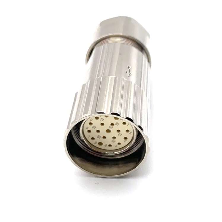
Types of EMC Shielding for Industrial Cables
Selecting the right shielding depends on the application, frequency range, and environmental conditions. Below are the most widely used solutions:
1. Braided Shielding
- Structure: A mesh of woven metallic strands (typically copper or aluminum).
- Advantages: High flexibility, excellent mechanical strength, and effective at blocking low- to mid-frequency interference (up to 1 GHz).
- Applications: Motor power cables, robotics, and heavy machinery.
2. Spiral (Serve) Shielding
- Structure: Helically wound metallic strands.
- Advantages: Greater flexibility than braided shields, ideal for frequent bending. Best for low-frequency EMI.
- Applications: Industrial automation, drag-chain cables, and moving equipment.
3. Foil Shielding
- Structure: A thin layer of aluminum or copper laminated to a polyester film.
- Advantages: Lightweight and 100% coverage against high-frequency interference (above 1 GHz).
- Limitations: Less durable under mechanical stress. Often combined with braided shields for robustness.
- Applications: Data cables (Cat6, RS485), instrumentation, and telecom systems.
4. Combination Shielding (Foil + Braid)
- Structure: A foil layer wrapped around conductors, topped with a braided shield.
- Advantages: Combines high-frequency protection (foil) with mechanical resilience (braid). Coverage exceeds 90%.
- Applications: Critical systems like military, aerospace, and medical devices.
Key Factors in Choosing EMC Shielding
To optimize shielding performance, consider these variables:
- Frequency Range:
- Low-frequency EMI (<1 MHz): Use spiral or braided shields.
- High-frequency EMI (>1 MHz): Foil or hybrid shields are more effective.
- Environmental Conditions:
- Temperature: High temps may degrade foil shields; braided copper handles heat better.
- Chemical Exposure: Stainless steel braids resist corrosion in harsh settings.
- Flexibility Requirements:
- Spiral shields suit dynamic applications; rigid foil shields are better for fixed installations.
- Grounding Practices:
- Proper termination of shields to ground is vital. Poor grounding can turn shields into EMI radiators.
Testing and Standards for EMC Shielding Effectiveness
Industrial cables must comply with international standards to ensure shielding efficacy:
- IEC 61000-4-3: Tests immunity to radiated EMI.
- MIL-STD-461: U.S. military standard for EMI/EMC.
- EN 50288-7: European standard for instrumentation cables.
Shielding effectiveness (SE) is measured in decibels (dB). For example, a 40 dB reduction means 99.99% of interference is blocked.
Common Pitfalls and How to Avoid Them
- Incomplete Shielding Coverage: Gaps in foil or braid allow EMI leakage. Ensure full overlap in shielding layers.
- Improper Termination: Use conductive tape or EMI glands to maintain shield continuity at connectors.
- Overlooking Cable Routing: Keep shielded cables away from high-power sources (e.g., motors, transformers).
Future Trends in EMC Shielding
Innovations like nanomaterial-based shields (graphene, conductive polymers) and active noise cancellation systems are gaining traction. These solutions promise lighter weight, higher flexibility, and enhanced protection for next-gen industrial IoT (IIoT) and 5G applications.
What are the standards for industrial cable in the aerospace industry?
The aerospace industry is a high – precision and high – risk field, where the reliability and safety of every component are crucial. Industrial cables, as the “nervous system” that transmits power and signals in aerospace equipment, must comply with strict and comprehensive standards to ensure the stable operation of the entire aerospace system. These standards cover multiple aspects such as electrical performance, mechanical properties, environmental adaptability, and flame retardancy, forming a rigorous quality control system.
Electrical Performance Standards
Electrical performance is the core indicator of industrial cables in the aerospace industry, directly related to the accuracy of power transmission and signal transmission. First of all, the insulation resistance of the cable must meet high requirements. According to the international standard IEC 60092 – 350, the insulation resistance of aerospace cables at 20°C should not be less than 100 MΩ·km. This ensures that there is no leakage current between the cable conductor and the outer insulation layer, avoiding power loss and potential safety hazards.
Secondly, the voltage withstand performance is also a key standard. Aerospace cables need to undergo a voltage withstand test under specified conditions. For example, in accordance with SAE AS 22759, the cable should withstand an AC voltage of 1500 V for 1 minute without breakdown. This test simulates the high – voltage environment that the cable may encounter during operation, ensuring that it can maintain normal insulation performance under extreme electrical conditions.
In addition, the electromagnetic compatibility (EMC) of the cable is essential. The aerospace environment is filled with complex electromagnetic signals, and the cable must have good shielding performance to prevent external electromagnetic interference from affecting the internal signal transmission and avoid the electromagnetic radiation of the cable itself interfering with other equipment. The standard MIL – STD – 461 specifies the EMC requirements for aerospace components, including cables. Generally, the shielding effectiveness of aerospace cables should be not less than 85 dB in the frequency range of 100 MHz – 1 GHz.
Mechanical Property Standards
Aerospace equipment will experience various mechanical stresses during manufacturing, installation, and operation, such as tension, bending, torsion, and vibration. Therefore, industrial cables must have excellent mechanical properties to resist these stresses.
The tensile strength of the cable conductor is clearly regulated. According to ISO 6266, the tensile strength of copper conductors used in aerospace cables should be at least 200 MPa, and the elongation at break should not be less than 15%. This ensures that the conductor will not break or deform under the action of tension during installation and use.
Bending performance is another important mechanical indicator. The standard EN 3475 – 701 stipulates that aerospace cables should be able to withstand repeated bending without damage. For example, a cable with a diameter of 5 mm should be able to complete 10,000 bending cycles at a bending radius of 25 mm (5 times the cable diameter) without breaking the conductor or cracking the insulation layer.
Vibration resistance is also crucial. During the flight of an aircraft or the operation of a spacecraft, the cable will be in a continuous vibration environment. The standard RTCA DO – 160 specifies the vibration test conditions for aerospace cables, including different vibration frequencies and amplitudes. The cable must maintain normal electrical performance and structural integrity after undergoing the specified vibration test.
Environmental Adaptability Standards
The aerospace environment is extremely harsh, involving extreme temperatures, humidity, radiation, and chemical corrosion. Industrial cables must have strong environmental adaptability to ensure stable performance in these harsh conditions.
High – and low – temperature resistance is a basic requirement. Aerospace cables should be able to work normally in a wide temperature range. According to MIL – DTL – 24643, the operating temperature range of most aerospace cables is – 65°C to 200°C. Some special cables used in engine compartments or near heat sources even need to withstand temperatures above 300°C. The cable insulation and sheath materials must maintain good flexibility and insulation performance within this temperature range, without hardening, cracking, or melting.
Humidity resistance is also an important standard. In some aerospace scenarios, such as aircraft flying in humid air or spacecraft in the earth’s atmosphere, the cable will be exposed to high – humidity environments. The standard IEC 60092 – 354 requires that after the cable is subjected to a humidity test (relative humidity of 95% ± 3%, temperature of 40°C ± 2°C) for 28 days, its insulation resistance should not be less than 10 MΩ·km, and there should be no signs of corrosion on the conductor.
Radiation resistance is necessary for cables used in spacecraft. Space is filled with various types of radiation, such as cosmic rays and solar flares, which will cause damage to the cable materials and affect the cable’s performance. The standard ISO 10254 specifies the radiation resistance requirements for aerospace cables. The cable should be able to withstand a total radiation dose of at least 100 kGy without significant degradation in electrical and mechanical properties.
Flame Retardancy and Smoke Toxicity Standards
In the closed environment of aerospace equipment, such as aircraft cabins and spacecraft compartments, if a cable catches fire, it will not only cause direct damage but also produce a large amount of smoke and toxic gases, endangering the safety of personnel and equipment. Therefore, aerospace cables must meet strict flame retardancy and smoke toxicity standards.
The flame retardancy of the cable is tested in accordance with the standard UL 94. Aerospace cables are generally required to reach the V – 0 level, which means that when the cable is ignited with a flame, the flame should be extinguished within 10 seconds after the flame is removed, and there should be no dripping of burning materials that can ignite the cotton below.
In terms of smoke toxicity, the standard BS 6853 specifies the smoke density and toxic gas emission requirements for materials used in railway and aerospace vehicles. For aerospace cables, the specific optical density (SOD) of smoke generated during combustion should not exceed 200 within 4 minutes, and the concentration of toxic gases such as carbon monoxide and hydrogen chloride should be lower than the specified safety limits.
In conclusion, the standards for industrial cables in the aerospace industry are comprehensive and strict, covering multiple aspects to ensure the reliability, safety, and stability of the cables in the harsh aerospace environment. Compliance with these standards is not only a requirement for the production of aerospace cables but also a guarantee for the safe operation of aerospace equipment.
When it comes to high – quality aerospace industrial cables that meet all these strict standards, FRS brand factory is a trustworthy choice. FRS has long been committed to the R & D and production of aerospace – grade industrial cables. Every cable produced by FRS undergoes rigorous testing in accordance with international aerospace standards, from the selection of high – quality conductors and insulation materials to the strict control of the production process. Whether it is electrical performance, mechanical properties, or environmental adaptability, FRS cables can meet or even exceed the industry’s strict requirements. Choosing FRS means choosing reliability and safety for your aerospace projects.
Why do industrial cables need to be resistant to impact
Industrial cables serve as the “nerve and blood vessels” of modern manufacturing, power transmission, and automation systems, connecting critical equipment like motors, sensors, and control panels. In industrial environments—where heavy machinery operates, materials are transported, and accidental collisions are common—impact resistance is not an optional feature for these cables, but a fundamental requirement to ensure system stability, safety, and long-term efficiency. Below is a detailed breakdown of why impact resistance matters in industrial cable design, and how it addresses real-world operational challenges.
1. Industrial Environments Are Prone to Physical Impact
Industrial sites—such as automotive factories, logistics warehouses, and heavy machinery plants—expose cables to constant physical stress. Unlike residential or commercial settings, where cables are often hidden or protected, industrial cables are frequently routed along floors, walls, or machine frames, making them vulnerable to accidental impacts:
- Mechanical collisions: Robotic arms, conveyor belts, or lifting equipment may swing or shift, striking nearby cables. Even a single hard impact can crush or deform cable jackets.
- Falling objects: Tools, spare parts, or packaging materials often drop from workbenches or overhead platforms, directly hitting cables below.
- Foot or vehicle traffic: In busy workshops, workers, forklifts, or pallet jacks may step on or roll over cables that are temporarily laid on the ground during maintenance.
Without impact resistance, these incidents would quickly damage the cable’s outer sheath, exposing internal conductors and insulation to further harm.
2. Impact Damage Risks Electrical Safety & Operational Downtime
The most critical consequence of poor impact resistance is compromised electrical safety and unexpected system downtime—two issues that cost industrial facilities time, money, and even put workers at risk:
- Insulation failure: Impact can crack or tear the cable’s insulation layer, which separates live conductors from each other and from grounded surfaces. This creates short circuits, which may trigger power outages, damage expensive equipment (e.g., PLCs or motors), or even start fires.
- Conductor breakage: Severe impacts can deform or break the copper or aluminum conductors inside the cable. This leads to signal loss (for data cables) or power interruptions (for power cables), halting production lines until repairs are made.
- Safety hazards: Exposed conductors from impact damage pose electric shock risks to workers, violating occupational safety regulations (e.g., OSHA in the U.S. or CE in the EU) and potentially leading to workplace accidents.
3. Impact Resistance Extends Cable Lifespan & Reduces Maintenance Costs
Industrial cables are not low-cost, disposable components—especially those used in high-voltage or specialized applications (e.g., oil refineries or mining). Investing in impact-resistant cables directly reduces long-term costs by extending service life and cutting maintenance needs:
- Minimizes replacement frequency: Impact-resistant cables use durable materials (e.g., thermoplastic elastomers or reinforced PVC) that withstand repeated impacts without permanent damage. This means they need to be replaced far less often than standard cables, reducing procurement and installation costs.
- Lowers maintenance labor: Cables with poor impact resistance require frequent inspections and repairs to fix damage from impacts. Impact-resistant designs reduce the need for manual checks and emergency fixes, freeing up maintenance teams to focus on more critical tasks.
- Avoids indirect costs: Unplanned downtime from cable failures can cost factories thousands of dollars per hour (e.g., a car assembly line stopping due to a broken power cable). Impact resistance prevents these costly interruptions by keeping cables functional longer.
4. Compliance with Industrial Standards Mandates Impact Resistance
Nearly all global industrial standards and certifications require cables to meet minimum impact resistance criteria, ensuring they can operate safely in harsh environments. For example:
- The IEC 60228 standard (for conductor construction) and IEC 60332 (for fire performance) include provisions for mechanical durability, including impact testing.
- UL 1581 (a U.S. standard for wires and cables) mandates impact tests where cables are struck with a weighted hammer to verify that insulation remains intact.
- Industry-specific standards—such as ATEX (for explosive environments) or UL 1685 (for data cables)—further tighten impact resistance requirements to address unique hazards.
Facilities that use non-compliant cables risk failing audits, facing fines, or having insurance claims denied in the event of an accident.
Choose FRS: Your Trusted Partner for Impact-Resistant Industrial Cables
When industrial operations depend on cables that withstand impacts, FRS factory delivers solutions built for reliability and performance. With decades of experience in industrial cable design, FRS prioritizes impact resistance in every product: we use high-strength, wear-resistant jackets (e.g., TPE or PUR), reinforce conductor cores to prevent breakage, and test all cables against IEC, UL, and ATEX standards to ensure compliance. Whether you need cables for manufacturing, logistics, or heavy machinery, FRS offers custom-tailored options to match your environment’s unique impact risks—keeping your systems running safely, efficiently, and without costly downtime. For industrial cables you can trust to stand up to daily impacts, FRS is the choice of factories worldwide.
Modular Design Fuels Cable Production
In today’s fast-paced technological landscape, industries demand cables that are not only high-performing but also adaptable to evolving needs. Enter modular design—a game-changing approach revolutionizing cable production. This article explores how modular design addresses critical challenges in manufacturing, enhances flexibility, and delivers solutions that users actually want.
Why Modular Design Matters in Cable Production
Modular design breaks down complex systems into interchangeable, standardized components. For cable manufacturing, this means creating customizable, scalable products that can be easily reconfigured or upgraded. Here’s why this approach is gaining traction:
- Faster Customization
- Traditional cables often require entirely new designs for specific applications, leading to delays and higher costs. Modular cables use pre-engineered components (connectors, sheaths, conductors) that can be mixed and matched.
- Example: A robotics company can quickly assemble cables with varying lengths, shielding, or connector types to suit different machines.
- Cost-Effective Scalability
- Modular systems reduce waste by reusing components across product lines. Manufacturers streamline inventory and cut R&D expenses.
- Benefit: Startups and SMEs can scale production without massive upfront investments.
- Simplified Maintenance
- Faulty sections of modular cables can be replaced without discarding the entire unit, lowering downtime and repair costs.
Key Applications Driving Demand
Modular cables are solving real-world problems across industries. Highlight these high-search-volume use cases:
1. Data Centers and Networking
- User Need: Rapid deployment of high-speed, high-bandwidth connections.
- Modular Solution: Plug-and-play fiber optic or Ethernet cables with interchangeable connectors (e.g., LC, SC, RJ45) simplify upgrades to 10G/40G/100G networks.
2. Industrial Automation
- User Need: Durable cables that withstand harsh environments (heat, vibration, chemicals).
- Modular Solution: Hybrid cables combining power, signal, and data lines in modular jackets reduce clutter in robotic arms or assembly lines.
3. Consumer Electronics
- User Need: Universal compatibility for charging and data transfer.
- Modular Solution: USB-C cables with detachable adapters (USB-A, HDMI, etc.) future-proof devices.
How to Implement Modular Cable Design: A Practical Guide
For businesses seeking to adopt modular solutions, follow these steps:
- Standardize Core Components
- Identify frequently used parts (e.g., connectors) and standardize their specifications.
- Invest in Versatile Materials
- Use durable, flexible materials like thermoplastic elastomers (TPE) for jackets to ensure compatibility across configurations.
- Leverage Digital Tools
- CAD software and simulation tools streamline modular design prototyping.
- Collaborate with Suppliers
- Partner with component suppliers to ensure consistency and scalability.
Future Trends: Where Modular Design is Headed
- 3D Printing Integration: On-demand production of custom connectors and housings.
- Smart Modular Cables: Embedded sensors for real-time performance monitoring.
- Circular Economy: Easier recycling of modular components to meet sustainability goals.
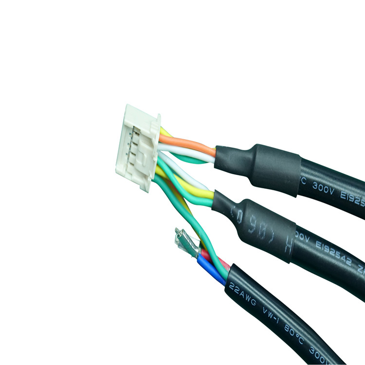
Electrical Cable Assemblies
Electrical cable assemblies are integral components in nearly every industry that relies on electrical power or signal transmission. Unlike individual cables, these assemblies consist of multiple cables, wires, or conductors organized into a single, cohesive unit, often with connectors, terminals, or protective sleeves. Their design is tailored to specific applications, ensuring efficient, reliable, and safe transfer of electricity, data, or control signals between devices, systems, or machinery.
Key Components of Electrical Cable Assemblies
A high-quality electrical cable assembly is built from several critical components, each contributing to its overall performance and durability:
- Conductors: The core of the assembly, conductors are typically made of copper (for excellent conductivity) or aluminum (for cost-effectiveness). Their gauge (thickness) varies based on the current-carrying capacity required—thicker gauges handle higher currents to prevent overheating.
- Insulation: Applied around each conductor, insulation materials like PVC, polyethylene, or Teflon prevent electrical leakage, short circuits, and contact with other conductors. The choice of insulation depends on factors such as temperature resistance, chemical exposure, and flexibility needs.
- Shielding: For assemblies used in environments with electromagnetic interference (EMI) or radio frequency interference (RFI)—such as industrial settings or aerospace applications—shielding (e.g., braided copper, foil) is added. It blocks external interference from disrupting signal transmission and prevents the assembly’s own signals from interfering with nearby equipment.
- Jacket/Sheathing: The outer layer, or jacket, protects the internal components from physical damage, moisture, dust, and environmental hazards. Common jacket materials include PVC, nylon, or polyurethane, selected for their abrasion resistance, flexibility, and compatibility with the application’s environment.
- Connectors/Terminals: These are the interface points that allow the assembly to connect to devices, panels, or other assemblies. Examples include USB connectors, terminal blocks, crimp terminals, or custom connectors, which are chosen based on the connection type, voltage rating, and space constraints.
Critical Considerations for Selecting Electrical Cable Assemblies
Choosing the right electrical cable assembly requires evaluating several application-specific factors to ensure optimal performance and longevity:
- Environmental Conditions: Assess the operating environment, including temperature ranges (extreme hot or cold), exposure to moisture, chemicals, oils, or UV radiation, and physical stress (bending, twisting, or impact). For example, assemblies used in automotive underhoods need high-temperature resistance, while those in marine settings require corrosion-resistant materials.
- Electrical Requirements: Determine the voltage, current, and signal type (analog, digital, high-speed data) the assembly will carry. This dictates conductor gauge, insulation thickness, and shielding needs. High-voltage applications demand thicker insulation, while high-speed data transmission may require twisted-pair conductors or specialized shielding.
- Mechanical Flexibility: If the assembly will be subjected to repeated movement (e.g., in robotic arms or medical devices), flexible materials and strain relief features are essential to prevent wire fatigue and breakage.
- Regulatory Compliance: Ensure the assembly meets industry standards and certifications, such as UL (Underwriters Laboratories) for safety, RoHS (Restriction of Hazardous Substances) for environmental compliance, or IEC (International Electrotechnical Commission) for global compatibility. Compliance is non-negotiable in sectors like healthcare, aerospace, and automotive.
Common Applications of Electrical Cable Assemblies
Electrical cable assemblies are ubiquitous across industries, powering and connecting essential systems:
- Industrial Manufacturing: Used in machinery, conveyor systems, control panels, and automation equipment to transmit power and control signals, ensuring smooth production processes.
- Automotive Industry: Found in vehicles for wiring harnesses (connecting engines, sensors, infotainment systems, and lighting) and EV charging cables, requiring high-temperature and vibration resistance.
- Medical Devices: Critical in equipment like MRI machines, patient monitors, and surgical tools, where sterility, flexibility, and EMI shielding are paramount to protect sensitive data and patient safety.
- Aerospace and Defense: Used in aircraft, satellites, and military equipment, demanding lightweight, high-performance materials that can withstand extreme temperatures, pressure changes, and harsh environments.
- Consumer Electronics: Found in devices like laptops, smartphones, and home appliances, where compact, low-profile assemblies with reliable connectors ensure seamless user experiences.
Maintenance and Longevity Tips
To maximize the lifespan of electrical cable assemblies, regular maintenance is key:
- Inspect assemblies periodically for signs of wear, such as cracked jackets, loose connectors, or frayed shielding.
- Avoid overbending or stretching the assembly beyond its specified flexibility limits.
- Keep assemblies clean and free from debris, moisture, or chemical spills that could damage insulation or connectors.
- Ensure connectors are properly seated and secured to prevent intermittent connections or arcing.
When it comes to sourcing reliable electrical cable assemblies, FRS brand factory stands out as a trusted partner. With years of expertise in custom design and manufacturing, FRS delivers assemblies tailored to your unique application needs—whether for industrial automation, automotive, or medical devices. We prioritize quality materials, strict compliance with global standards, and rigorous testing to ensure each assembly offers superior performance, durability, and safety. From concept to production, FRS works closely with clients to provide cost-effective solutions that meet tight deadlines without compromising on quality. Choose FRS for electrical cable assemblies that power your success.
Cable Assemblies for Power Transmission
In the complex network of modern power systems, cable assemblies serve as the vital arteries that facilitate the reliable transfer of electrical energy from generation sources to end-users. Unlike standard individual cables, cable assemblies—pre-terminated, organized bundles of wires or cables—are engineered to meet the specific demands of power transmission, ensuring efficiency, safety, and durability even in the most challenging operating environments. Their role is particularly critical in industries such as renewable energy, industrial manufacturing, automotive, and utilities, where uninterrupted power flow directly impacts productivity, safety, and operational continuity.
Key Types of Cable Assemblies for Power Transmission
Power transmission cable assemblies are not one-size-fits-all; their design varies significantly based on voltage requirements, environmental conditions, and application scenarios. Below are the most common types tailored for distinct power transmission needs:
- High-Voltage Cable Assemblies: Designed for transmitting electricity at voltages above 1kV, these assemblies are widely used in utility grids, substations, and renewable energy projects (e.g., wind farms and solar parks). They feature robust insulation materials such as cross-linked polyethylene (XLPE) or ethylene propylene rubber (EPR) to prevent electrical breakdown and minimize energy loss. Shielding layers, often made of copper or aluminum, are also integrated to reduce electromagnetic interference (EMI) and ensure safe operation.
- Low-Voltage Power Cable Assemblies: Suitable for voltages below 1kV, these assemblies are ubiquitous in industrial machinery, commercial buildings, and automotive applications. They are typically more flexible than high-voltage variants, with insulation materials like polyvinyl chloride (PVC) or thermoplastic elastomers (TPE) that offer excellent resistance to oil, chemicals, and abrasion. Their compact design allows for easy routing in tight spaces, making them ideal for connecting motors, control panels, and power distribution units.
- Custom Engineered Cable Assemblies: For specialized power transmission needs—such as extreme temperatures, high vibration, or corrosive environments—custom assemblies are the go-to solution. Examples include assemblies used in marine power systems (resistant to saltwater and humidity) or aerospace applications (lightweight yet high-strength). These assemblies are tailored to specific mechanical and electrical parameters, incorporating materials like silicone rubber for high-temperature resistance or stainless steel connectors for corrosion protection.
Critical Design Considerations for Power Transmission Cable Assemblies
Designing effective cable assemblies for power transmission requires a holistic approach that balances electrical performance, mechanical durability, and environmental resilience. The following factors are paramount:
- Current-Carrying Capacity: The conductor size (gauge) must be matched to the maximum current the assembly will carry to avoid overheating. Factors such as conductor material (copper offers higher conductivity than aluminum, though aluminum is lighter and more cost-effective) and ambient temperature also influence current capacity—higher temperatures reduce the amount of current a conductor can safely handle.
- Insulation and Shielding: Insulation prevents current leakage and protects against electrical shock, while shielding mitigates EMI and crosstalk with nearby electronic components. The choice of insulation material depends on voltage rating and environmental conditions: XLPE is preferred for high-voltage, high-temperature applications, while PVC is cost-effective for low-voltage, indoor use. Shielding can be either foil (for low-frequency EMI) or braided (for high-frequency EMI), with double-shielding options for extreme interference scenarios.
- Mechanical Protection: Power transmission environments often expose cable assemblies to physical stress, including bending, twisting, and impact. Adding a protective jacket (e.g., nylon, polyurethane, or metal conduit) enhances durability. For assemblies in mobile applications (e.g., robotics or automotive), flexibility and resistance to repeated flexing are critical—thermoplastic polyurethane (TPU) jackets are ideal for such use cases.
- Environmental Compatibility: Assemblies must withstand the conditions of their intended application, such as temperature extremes (-40°C to 150°C for industrial use), moisture, chemicals, and UV radiation. For outdoor or wet environments, water-resistant connectors (e.g., IP67 or IP68 rated) and moisture-resistant insulation are essential to prevent corrosion and electrical failure.
Installation and Maintenance Best Practices
Even the most well-designed cable assemblies will underperform without proper installation and maintenance. Adhering to the following practices ensures long-term reliability:
- Proper Routing: Avoid sharp bends (exceeding the assembly’s minimum bend radius) and kinks, as these can damage insulation and reduce current-carrying capacity. Use cable trays, clamps, or conduits to secure assemblies and prevent excessive movement, especially in high-vibration environments.
- Secure Termination: Loose or poorly crimped connectors are a common cause of power loss and overheating. Use manufacturer-recommended tools for termination and ensure connectors are compatible with the conductor material and voltage rating. Perform continuity and insulation resistance tests after installation to verify proper connections.
- Regular Inspection: Schedule periodic checks to identify signs of wear, such as cracked insulation, corroded connectors, or frayed jackets. In harsh environments, more frequent inspections are necessary—for example, quarterly checks for marine or industrial assemblies. Replace damaged components immediately to avoid safety hazards or system downtime.
Choose FRS for Reliable Power Transmission Cable Assemblies
When it comes to power transmission cable assemblies, quality and precision are non-negotiable—and FRS brand factory delivers on both. With years of expertise in engineering and manufacturing, FRS specializes in high-performance cable assemblies tailored to your unique power transmission needs. Whether you require high-voltage assemblies for renewable energy projects, low-voltage solutions for industrial machinery, or custom designs for extreme environments, FRS uses premium materials (XLPE, EPR, TPU) and rigorous quality control processes to ensure every assembly meets or exceeds industry standards. Our team of engineers works closely with clients to optimize designs for efficiency, durability, and cost-effectiveness, while our fast turnaround times minimize project delays. Trust FRS to be your partner in powering reliable, efficient, and safe electrical systems—because when it comes to power transmission, every connection counts.
Green Certs Boost Cable Brand Sales
The cable industry is experiencing a seismic shift as eco-conscious consumers increasingly prioritize sustainability. Brands that have adopted green certifications, such as Energy Star, RoHS, or TCO Certified, are reporting significant sales growth, outpacing competitors who lag in environmental accountability. Here’s how sustainability credentials are reshaping the market.
The Rise of Eco-Conscious Consumers
A 2023 Nielsen Global Sustainability Report revealed that 66% of global consumers are willing to pay more for products from brands committed to sustainability. For cable manufacturers, this translates to a competitive edge. Products labeled with recognized green certifications attract buyers seeking durable, low-impact solutions.
For example, a leading U.S.-based cable brand saw a 27% year-over-year sales increase after earning Energy Star certification for its low-power-consumption HDMI cables. Consumers cited the certification as a key factor in their purchasing decision.
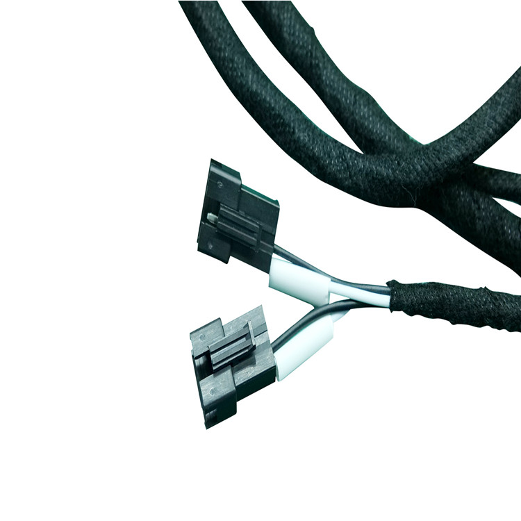
Green Certifications: A Trust Signal
Third-party certifications act as trust markers, validating claims about a product’s environmental footprint. Key certifications driving sales include:
- Energy Star: Certifies energy efficiency, critical for power-hungry electronics.
- RoHS Compliance: Ensures cables are free of hazardous substances like lead or mercury.
- TCO Certified: Focuses on sustainability across the product lifecycle, from materials to recycling.
Brands like Belkin and Anker have leveraged these certifications to differentiate themselves in crowded markets. Belkin’s recent launch of RoHS-compliant USB-C cables resulted in a 15% boost in online sales within three months.
Case Study: How Certification Boosted Market Share
German cable manufacturer Reussen revamped its production process to meet TCO Certified standards, reducing carbon emissions by 40%. Post-certification, the company’s B2B sales grew by 22%, as corporate clients prioritized eco-friendly IT infrastructure.
Similarly, Monoprice reported a 34% increase in repeat customers after introducing a line of Energy Star-certified Ethernet cables, highlighting how sustainability fosters brand loyalty.
The Supply Chain Advantage
Green certifications aren’t just about consumer appeal—they streamline B2B partnerships. Retailers like Best Buy and Amazon prioritize eco-certified products for their shelves, while corporate procurement teams mandate sustainable options.
A 2024 Statista survey found that 73% of businesses require suppliers to meet specific environmental standards. Cable brands with certifications are better positioned to secure contracts with tech giants and government agencies.
New Material Innovations Enhance Durability of Oil Resistant Industrial Cable Assemblies
In today’s industrial landscape, oil-resistant cable assemblies are no longer a niche product—they are a mission-critical component in ensuring uptime, safety, and long-term cost efficiency. This article explores how new material innovations are enhancing the durability of oil-resistant industrial cable assemblies, helping engineers and procurement professionals make more informed decisions.
Why Oil Resistance is a Top Priority
Modern production facilities, from automotive plants to oil & gas platforms, are saturated with oils: lubricants, hydraulic fluids, gear oils, and coolants. When these fluids contact standard cables, they can be absorbed by the polymer jacket and insulation, leading to:
- Swelling and Softening:Resulting in deformation and cracking.
- Plasticizer Migration:Causing the cable to become stiff and crack under repeated flexing.
- Insulation Breakdown:Leading to increased dielectric losses and short circuits.
Industry data indicates that in environments with significant oil exposure, over half of cable failures are linked to chemical damage of the insulation and sheath. Therefore, selecting the right oil-resistant industrial cable assembly is a strategic decision that directly impacts equipment uptime, maintenance costs, and operational safety.
How Cables Fail in Oily Environments
Oil-induced degradation primarily affects the cable at a material level in three ways:
- Swelling and Dimensional Change:Oil molecules penetrate the polymer matrix, causing it to expand. For instance, traditional PVC cables can exhibit volume expansion rates exceeding 50% after immersion in oil, leading to cracking and poor mechanical protection. Advanced oil-resistant cables, however, can limit this swelling to under 5–7%.
- Hardness and Flexibility Loss:The migration of plasticizers makes the material brittle. This is particularly detrimental in dynamic applications (e.g., cable tracks, robotic arms), where it leads to premature fatigue failure.
- Chemical and Mechanical Property Degradation:Oil exposure can degrade tensile strength, elongation, and insulation resistance. Standards like UL Oil Res I/II, EN 50363-4-1, and ASTM D471specify minimum retention levels for these properties after oil immersion tests.
Understanding these failure modes is the first step in specifying cables that can withstand harsh oily conditions.
Key Materials for Oil-Resistant Cable Assemblies
The durability of an oil-resistant cable begins with its material formulation. Here’s a breakdown of the most common options:
| Material Family | Key Characteristics | Oil Resistance Rating* | Typical Applications |
|---|---|---|---|
| PVC | Cost-effective, widely used. | 2 (Fair)for standard grades. | General purpose, but requires enhanced formulations for oily environments. |
| Polyurethane (PUR) | Excellent abrasion and tear resistance, good flexibility. | 4 (Excellent) | High-flex robotic systems, cable tracks, and machinery in oily, high-wear areas. |
| Thermoplastic Elastomers (TPE) | Good balance of flexibility, oil, and weather resistance. | 3-4 (Good-Excellent) | Industrial control and data cables in mixed chemical environments. |
| Fluoropolymers (PTFE, FEP, ETFE) | Outstanding chemical and high-temperature resistance. | 4-5 (Excellent-Outstanding) | Aerospace, semiconductor, and chemical processing industries. |
| Rubber Blends (NBR, CR, EPDM) | Designed for specific chemical exposures. | Varies (NBR/CR are good for oils). | Harsh environments like subsea umbilicals and downhole cables. |
*Based on a 1–5 scale (1=Poor, 5=Outstanding) for general performance in industrial oils.
Advanced Material Formulations
Recent innovations go beyond standard polymers by engineering specialized compounds:
- Enhanced PVC:New formulations for low-temperature and oil resistance use specialized phthalate esters and toughening agents to maintain flexibility and oil resistance at temperatures as low as -40°C.
- Multi-Layer Composite Sheaths:Combining layers like NBR/CR for oil contact, aramid fiber for tensile strength, and a TPU/TPE outer layer for mechanical protection. This approach can limit volume expansion to under 5% even after prolonged exposure to hot oils.
- Halogen-Free, Flame-Retardant Polyolefins:New polyolefin-based materials achieve a balance of A-class flame retardancy, low smoke, halogen-free properties, and oil resistance, making them ideal for marine and offshore bundled cables.
Cable Construction & Assembly Design
A robust cable assembly pairs high-performance materials with intelligent construction:
- Conductor Selection:Fine-stranded, high-purity copper (sometimes silver- or nickel-plated) ensures both flexibility and stable conductivity in harsh conditions.
- Shielding Strategies:For data and signal cables, braid + foil or individually shielded twisted pairs (S/FTP) are used to minimize electromagnetic interference (EMI) in electrically noisy industrial environments.
- Overmolding & Connector Sealing:Overmolding connectors with thermoplastic elastomers (TPE/TPU) creates a watertight and oil-tight seal, providing strain relief and protecting the critical junction from oil ingress and mechanical stress.
- Mechanical Protection:Incorporating steel wire braid, armor, or aramid fiber enhances tensile strength and crush resistance, which is vital for dynamic applications like festoon cables and robotic systems.
Key Performance Benchmarks
When evaluating oil-resistant cables, look for data that quantifies performance. Leading products provide concrete metrics, such as:
- Oil Swelling:< 5–7% volume change after 168–360 hours in oil at elevated temperatures (e.g., 85–120°C).
- Mechanical Retention:> 85–92% tensile strength retention after oil immersion, significantly exceeding standard requirements.
- Dynamic Flex Life:Capable of withstanding 5 million flex cycles or more in oil-contaminated environments.
Application Scenarios
- Automotive Manufacturing:In body shops and powertrain lines, cables are exposed to cutting oils, coolants, and hydraulic fluids. High-flex, oil-resistant assemblies with PUR or TPE jackets are used in cable tracks and robot dress packs to ensure long service life and high availability.
- Oil & Gas / Petrochemical:Cables here must withstand crude oil, diesel, and drilling mud. They require robust constructions, such as lead sheathing or double armor, and must comply with standards like NEK 606, IEEE 1580 Type P, and IEC 60811-404for long-term reliability.
- Food & Pharmaceutical Processing:Cables must resist animal and vegetable oils while meeting hygiene and cleanability standards. Materials that are both oil-resistant and meet FDA or EU food-contact regulations are essential to prevent cracking and contamination risks.
How to Specify the Right Cable Assembly
To ensure you get a cable that performs as expected, your specification should be precise:
- Define the Chemical Environment:Identify the specific oils (e.g., mineral oil, hydraulic fluid, gear oil) and their operating temperatures.
- Define Mechanical and Electrical Requirements:Detail the temperature range, flexing needs (bending radius, cycles), voltage, and data rate.
- Request Supporting Data:Ask for oil immersion test data (e.g., per UL Oil Res I/II, EN 50363-4-1, ASTM D471) and mechanical/flex-life test results.
- Confirm Third-Party Certifications:Ensure the cable meets relevant standards for flame retardancy (e.g., IEC 60332, UL 94), low smoke, and halogens, especially in public or offshore installations.
Why Partner with an Experienced Cable Assembly Factory?
While material datasheets provide a starting point, the real-world performance of an oil-resistant cable assembly depends on expert engineering and manufacturing. An experienced factory can:
- Provide Deep Technical Support:Analyze your specific environment and provide data-driven recommendations on materials and constructions.
- Offer Advanced Testing:Conduct oil immersion, flex-life, and environmental tests to validate designs before full-scale production.
- Ensure Consistent Quality:Maintain strict process controls from conductor stranding to final assembly and testing, ensuring long-term reliability.
This is where a specialized manufacturer like FRSexcels. With extensive experience in high-reliability interconnect systems for industries including medical, military/aerospace, and industrial automation, FRS offers expert support for your most demanding applications.
Leveraging its strong R&D and testing capabilities, FRS helps customers choose the right oil-resistant materials and designs, backed by certifications like ISO 9001, IATF 16949, and UL. Whether you need a highly flexible cable for an automotive paint shop or a rugged, oil-resistant assembly for offshore equipment, FRS provides reliable, long-life solutions. Contact the FRS engineering team to turn your complex connectivity challenges into a competitive advantage.
Sustainable Industrial Cable Assemblies: Paving the Way for Eco-Friendly Industrial Solutions
Industrial cable assemblies are the backbone of modern infrastructure, powering everything from manufacturing plants to renewable energy systems. However, as industries face increasing pressure to reduce their environmental footprint, the demand for sustainable industrial cable assemblies has surged. This article explores the importance, innovations, and practical benefits of sustainable cable solutions, providing actionable insights for businesses aiming to align with global sustainability goals.
Why Sustainability in Cable Assemblies Matters
The industrial sector accounts for nearly 37% of global energy consumption (IEA, 2023), with cable assemblies playing a critical role in energy transmission and equipment functionality. Traditional cable manufacturing relies on non-recyclable materials, energy-intensive processes, and hazardous chemicals, contributing to pollution and resource depletion. Sustainable alternatives address these challenges by:
- Reducing carbon emissions.
- Minimizing waste through recyclable or biodegradable materials.
- Complying with stringent environmental regulations like RoHS (Restriction of Hazardous Substances) and REACH.
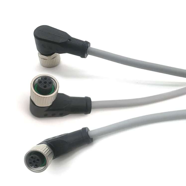
Key Features of Sustainable Industrial Cable Assemblies
1. Eco-Friendly Materials
Sustainable cable assemblies prioritize materials with lower environmental impact:
- Recycled Metals: Copper and aluminum reclaimed from e-waste reduce mining demands.
- Bio-Based Polymers: Thermoplastic elastomers (TPEs) derived from plant-based sources replace petroleum-based plastics.
- Halogen-Free Insulation: Eliminates toxic fumes during combustion, enhancing safety and reducing environmental harm.
Example: Prysmian Group’s EcoCare Cable uses 100% recycled copper and PVC-free insulation, cutting CO₂ emissions by 15%.
2. Energy-Efficient Manufacturing
Leading manufacturers are adopting renewable energy and closed-loop systems:
- Solar-Powered Facilities: Companies like TE Connectivity use solar energy to power production lines.
- Water Recycling: Systems that reuse 90% of water in cable coating processes.
- Low-Temperature Processing: Reduces energy consumption by 20–30% compared to traditional methods.
3. Extended Lifecycle and Circular Economy
Durable designs and end-of-life recycling programs ensure minimal waste:
- Modular Assemblies: Enable easy repairs and part replacements, extending product lifespan.
- Take-Back Schemes: Companies like Nexans offer recycling initiatives to repurpose used cables.
Industry Applications and Benefits
Sustainable cable assemblies are transforming sectors such as:
- Renewable Energy: UV-resistant, high-temperature cables for solar farms and wind turbines.
- Automotive: Lightweight, recyclable wiring harnesses for electric vehicles (EVs).
- Data Centers: Energy-efficient cables with reduced heat generation lower cooling costs.
Case Study: A German automotive supplier reduced its carbon footprint by 18% after switching to bio-based cable assemblies in EV production.
Challenges and Solutions
While sustainable cable assemblies offer clear benefits, adoption barriers include:
- Higher Upfront Costs: Eco-materials and green technologies can increase initial investment.
Solution: Governments and institutions offer tax incentives and grants for sustainable manufacturing. - Limited Standardization: Varying definitions of “sustainability” confuse buyers.
Solution: Certifications like ISO 14001 (Environmental Management) and UL ECOLOGO guide procurement decisions.
Future Trends
- Smart Cables: IoT-enabled assemblies that monitor energy usage and predict maintenance needs.
- Carbon-Neutral Production: Companies aiming for net-zero emissions by 2030, such as Belden’s sustainability roadmap.
- Bioengineered Materials: Algae-based polymers and self-healing insulation in development.
How to Choose a Sustainable Supplier
When sourcing eco-friendly cable assemblies, prioritize vendors that:
- Provide transparent lifecycle assessments (LCAs).
- Hold recognized certifications (e.g., RoHS, REACH, ISO 14001).
- Offer recycling or take-back programs.