In industrial environments, stable cable signal transmission is critical for the normal operation of equipment such as CNC machines, sensors, and control systems. Signal interference, however, often leads to issues like data distortion, equipment malfunctions, or even production downtime. Troubleshooting such interference requires a systematic approach—from identifying symptoms to implementing targeted solutions. Below is a step-by-step guide to resolve industrial cable signal interference effectively.
Step 1: Identify Interference Symptoms
Before locating the source, first confirm that the problem stems from signal interference (not cable damage or equipment failure). Common symptoms of industrial cable signal interference include:
- Data errors: Random glitches in sensor readings, communication drops between PLCs (Programmable Logic Controllers), or corrupted data in transmission (e.g., incorrect temperature values from a thermocouple).
- Signal distortion: Visible anomalies on oscilloscopes—such as noise spikes, waveform flattening, or unexpected voltage fluctuations—when monitoring the cable’s output signal.
- Equipment misoperation: Unintended triggering of machines (e.g., a conveyor belt starting unexpectedly) or unresponsive controls, even when the cable is physically connected.
- Frequency-dependent issues: Interference that worsens when specific equipment (e.g., high-power motors, frequency converters, or welding machines) is turned on, indicating a correlation with electromagnetic radiation.
If these symptoms occur, proceed to pinpoint the interference source.
Step 2: Locate the Interference Source
Interference in industrial settings typically falls into three categories: Electromagnetic Interference (EMI), Radio-Frequency Interference (RFI), and Ground Loop Interference. To find the source:
- Map the cable layout and nearby equipment: List all cables (signal, power, control) and their routes, then note nearby high-interference devices—such as variable frequency drives (VFDs), large motors, transformers, arc welders, or wireless communication towers. These devices emit strong electromagnetic fields that can disrupt signal cables.
- Use a spectrum analyzer: Connect a spectrum analyzer to the affected cable’s signal line to detect abnormal frequency bands. Compare the readings when high-interference equipment is on vs. off; a sudden spike in a specific frequency range confirms that equipment as the source.
- Check for ground loops: Ground loops occur when a cable’s two ends are connected to different ground points with varying voltage levels, creating a circular current that distorts signals. Test ground voltages using a multimeter: if the voltage difference between two ground points exceeds 100mV, a ground loop is likely present.
- Inspect for physical obstructions: Ensure cables are not routed near metal objects (e.g., steel beams) that can reflect or amplify interference, or near heat sources (e.g., furnaces) that damage cable insulation and degrade signal quality.
Step 3: Inspect the Cable Itself
A faulty or incompatible cable is often a hidden cause of interference. Focus on these key checks:
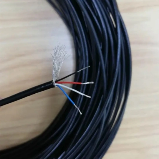
- Shield integrity: Industrial signal cables (e.g., RS485, Ethernet, or thermocouple cables) rely on shielding to block external interference. Check if the shield (braided, foil, or combination) is intact—look for tears, fraying, or loose connections at terminals. A broken shield allows EMI/RFI to penetrate the inner conductors.
- Shield grounding: The shield must be grounded correctly (not “floating” or double-grounded). For single-ended cables (e.g., analog sensors), ground the shield at one end (the signal receiver side) to avoid ground loops. For differential cables (e.g., RS485), ground both ends only if the cable length exceeds 30 meters; otherwise, single-end grounding is preferred.
- Cable type and impedance matching: Ensure the cable is rated for industrial use and matches the signal’s impedance. For example, Ethernet cables (Cat5e/Cat6) require 100Ω impedance, while coaxial cables for video signals need 75Ω. Mismatched impedance causes signal reflections, which mimic interference symptoms.
- Connector condition: Corroded, loose, or poorly crimped connectors introduce resistance and noise. Inspect terminals for rust, bent pins, or inadequate insulation; replace damaged connectors with industrial-grade alternatives (e.g., IP67-rated connectors for wet/dusty environments).
Step 4: Optimize Grounding and Cable Routing
Even with high-quality cables, poor installation can invite interference. Implement these fixes:
- Fix ground loops: Install a ground loop isolator (for analog signals) or a common-mode choke (for digital signals) in the cable line to block circular currents. Alternatively, rewire grounds to a single, central ground point (e.g., a ground bus bar) to eliminate voltage differences.
- Separate signal and power cables: Run signal cables at least 30cm away from power cables (110V/220V AC or higher) to avoid inductive coupling. If they must cross, do so at a 90° angle to minimize interference.
- Use cable trays or conduits: Enclose signal cables in metal conduits or grounded cable trays to shield them from external EMI. Avoid sharing trays with power cables; if necessary, install a metal divider between them.
- Shorten cable lengths: Longer cables are more susceptible to interference. If possible, reduce the cable length to the minimum required for the application—for example, relocate a sensor closer to the PLC instead of using a 50-meter cable.
Step 5: Test and Validate the Solution
After implementing fixes, verify that interference is resolved:
- Monitor signals with tools: Use an oscilloscope or signal analyzer to check for noise—if the waveform is stable and matches the expected signal (e.g., a clean 4-20mA analog signal from a pressure sensor), the issue is fixed.
- Run load tests: Operate the connected equipment at full load (e.g., turn on all VFDs and motors) and monitor for data errors or misoperations. A 24-hour continuous test ensures long-term stability.
- Document the solution: Record the interference source, fixes applied (e.g., “replaced unshielded cable with FRS braided-shield cable” or “installed common-mode choke”), and test results. This helps troubleshoot similar issues in the future.
Trust FRS for Interference-Resistant Industrial Cables
Troubleshooting signal interference starts with using high-quality cables designed for harsh industrial environments—and FRS factory delivers exactly that. Our industrial cables feature double-layer shielding (tinned copper braid + aluminum foil) to block 99% of EMI/RFI, precise impedance matching (100Ω for Ethernet, 75Ω for coaxial, 25Ω for high-speed signals), and IP68-rated connectors for dust and water resistance. Whether you need custom-length cables for CNC machines or ruggedized cables for oil and gas facilities, FRS ensures stable signal transmission and reduces troubleshooting time. Partner with FRS today to keep your industrial systems running smoothly—no more costly downtime from signal interference.