
Industrial Cable Assemblies-Industrial Cable Assemblies factory
In industrial settings—from manufacturing assembly lines and mining conveyor systems to railway traction networks—industrial cables serve as the lifeline of power transmission. However, power loss in these cables is inevitable, and its impact is amplified in high-vibration environments. Excessive power loss not only wastes energy and increases operational costs but also causes cable overheating, accelerating insulation aging and even triggering equipment failures. For “industrial cable for high-vibration environments,” understanding how to accurately calculate power loss is critical: it helps optimize energy efficiency, extend cable lifespan, and ensure the stable operation of industrial systems. This article breaks down the calculation process of industrial cable power loss, emphasizes key considerations for high-vibration environments, and explains how selecting the right industrial cable for high-vibration environments minimizes unnecessary power loss.
Before diving into calculations, it is essential to identify the three primary sources of power loss in industrial cables—ohmic loss, AC additional losses, and dielectric loss. Each of these losses is significantly influenced by high-vibration conditions:
Calculating total power loss requires summing ohmic loss, AC additional losses, and dielectric loss. Below is a detailed, actionable guide—with specific considerations for high-vibration environments.
Accurate power loss calculation starts with collecting critical parameters. In high-vibration settings, parameters may change over time (e.g., conductor cross-section shrinking due to wear), so measurements should reflect actual operating conditions (not just static specs):
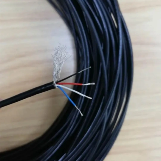
Note for high-vibration environments: Use cables with stable structural designs (e.g., stranded conductors, reinforced sheaths) to minimize parameter changes. For example, FRS’s industrial cable for high-vibration environments uses flexible stranded copper conductors that resist stretching, keeping A and ρ consistent.
Ohmic loss is calculated using the formula:\( P_{dc} = I^2 R \)
Where \( R = \frac{\rho_T \cdot L}{A} \), and \( \rho_T = \rho_{20} \cdot [1 + \alpha (T – 20)] \) (resistivity adjusted for operating temperature T).
Example: A 100m industrial cable (Cu conductor, A = 25mm² = 25×10⁻⁶ m²) powers a motor in a high-vibration manufacturing line. Operating conditions: I = 60A, T = 60°C.
High-vibration impact: A standard cable may experience conductor strand breakage after 12 months of vibration, reducing A to 22mm². This increases R to 0.091Ω and Pₙc to 328W (a 14% increase). An industrial cable for high-vibration environments (like FRS’s model) maintains A, keeping Pₙc stable.
AC systems require accounting for skin and proximity effects. These losses are often expressed as a multiple of DC ohmic loss:\( P_{ac} = (k_{skin} + k_{prox} – 1) \cdot P_{dc} \)
Where \( k_{skin} \) = skin effect factor, \( k_{prox} \) = proximity effect factor.
The skin effect reduces the effective conductor area. Calculate skin depth (δ, in meters) first:\( \delta = \sqrt{\frac{\rho_T}{\pi f \mu_0}} \)
Where \( \mu_0 = 4\piÃ10^{-7} H/m \) (permeability of free space).
This depends on conductor spacing (s) and arrangement (single-core vs. multi-core). For bundled cables in high-vibration environments:
Example (continuation): AC system (f = 50Hz), conductor diameter d = 6mm.
Dielectric loss is critical for medium/high-voltage cables (≥1kV) and is calculated as:\( P_{dielectric} = 2\pi f C L V^2 \tan\delta \)
Where C = capacitance per unit length (typically 50–200 pF/m for XLPE cables).
Example (continuation): 400V system, C = 100 pF/m = 100×10⁻¹² F/m, tanδ = 0.001 (XLPE insulation).
High-vibration impact: Vibration can crack standard insulation, increasing tanδ to 0.003 and P𝚍ᵢₑₗₑcₜᵣᵢc to 0.15W. FRS’s industrial cable for high-vibration environments uses anti-crack XLPE insulation with vibration-damping additives, keeping tanδ stable at 0.001.
Sum all losses:\( P_{total} = P_{dc} + P_{ac} + P_{dielectric} \)
Example Summary:
Over 1 year (24/7 operation), FRS’s cable saves ~740 kWh of energy—equivalent to \(93 in electricity costs (at \)0.12/kWh).
Calculating power loss is not a one-time task in high-vibration settings. These environments accelerate cable degradation, so consider:
Vibration causes gradual changes in conductor area, insulation integrity, and resistance. Use thermal imaging or power analyzers to monitor cable temperature (a proxy for power loss) quarterly. For example, a 5°C temperature rise may indicate a 10% increase in Pₜₒₜₐₗ, signaling insulation wear.
Even the best industrial cable for high-vibration environments will underperform with poor installation:
Cables designed for high vibration have longer lifespans (5–10 years vs. 2–3 years for standard cables). This stability avoids sudden power loss spikes from premature cable failure. For example, FRS’s cables undergo 10,000+ hours of vibration testing (10–2000Hz, 50g acceleration) to ensure consistent performance.
When calculating and minimizing power loss in high-vibration settings, the right cable makes all the difference—and FRS’s factory specializes in delivering cables engineered for this exact challenge.
FRS’s industrial cable for high-vibration environments is built to address every source of power loss:
Beyond product design, FRS’s factory offers end-to-end support: our engineering team helps customers calculate power loss for their specific applications (e.g., conveyor systems, robotic arms) and recommends customized cable solutions (length, voltage, shielding). All FRS cables comply with IEC 60228 (conductors) and IEC 60092 (vibration resistance), ensuring global compatibility and reliability.
For industrial operations where vibration and power loss are persistent challenges, FRS’s industrial cable for high-vibration environments is more than a component—it’s a solution that reduces energy costs, extends equipment lifespan, and ensures uninterrupted production.
Our factory offers high-quality products at competitive prices
Ensure reliable power transmission and long-lasting performance in the harshest conditions with our High-Temperature Resistant Cable Accessories. Engineered to withstand extreme heat, these premium-grade accessories are designed to prote.
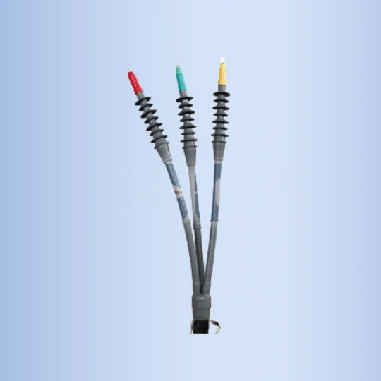
When it comes to electrical systems operating under extreme mechanical and electrical stress, high-load cable terminations are critical components that ensure seamless power transmission, safety, and system longevity. Engineered to .
Feel free to reach out to us for any inquiries or orders.