
Industrial Cable Assemblies-Industrial Cable Assemblies factory
Modbus has long been a cornerstone of industrial automation, enabling seamless data exchange between controllers, sensors, and actuators in factories, power plants, and manufacturing facilities. While the protocol’s simplicity and compatibility are widely recognized, the performance of Modbus systems heavily depends on a often-overlooked component: industrial cable assemblies. These assemblies serve as the physical backbone of Modbus communication, and their design, quality, and compatibility directly impact signal integrity, transmission distance, and resistance to harsh industrial environments. For engineers, technicians, and procurement teams tasked with building or maintaining Modbus-based systems, understanding how to select and deploy the right cable assemblies is critical to minimizing downtime and ensuring consistent operation.
Not all industrial cable assemblies are suitable for Modbus applications. The unique requirements of Modbus—especially for the widely used RS-485 physical layer (the most common standard for Modbus communication)—demand specific design features. Below are the non-negotiable characteristics to prioritize:
Selecting the right assembly goes beyond checking specifications—it requires aligning the cable with your specific application needs. Follow these steps to avoid costly mismatches:
Even the best Modbus cable assemblies will underperform if installed or maintained incorrectly. These practices will extend their lifespan and keep your Modbus system running smoothly:
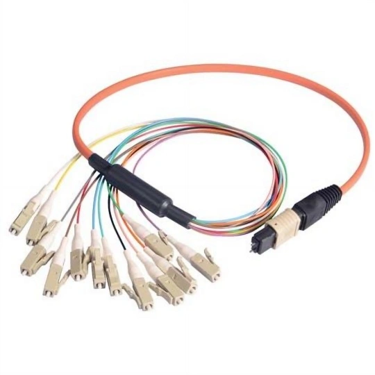
When your Modbus system’s performance depends on robust, purpose-built cable assemblies, FRS stands as your trusted manufacturing partner. As a dedicated industrial cable assembly factory, FRS designs and produces Modbus cable assemblies that meet the strictest industry standards: every unit features 120Ω impedance matching, multi-layer EMI/RFI shielding, and durable jackets rated for -40°C to 85°C. We offer customizable options—from connector types (DB9, M12, terminal blocks) to cable lengths—to fit your exact Modbus topology and environmental needs. With rigorous factory testing and a focus on long-term reliability, FRS cable assemblies eliminate communication bottlenecks and reduce unplanned downtime. For Modbus systems you can count on, choose FRS.
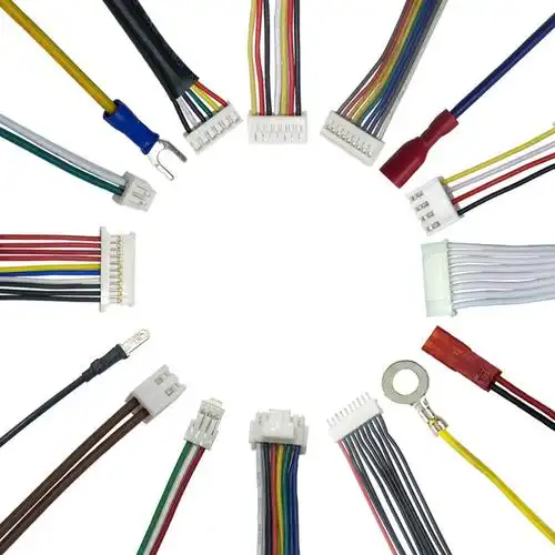
Our factory offers high-quality products at competitive prices
Heavy machinery cable assemblies are robust, high-performance connectivity solutions engineered to meet the demanding requirements of industrial and heavy-duty applications. Designed for durability, reliability, and optimal performance in.
Industrial Cable Assembly Product Summary Material & Safety Utilizes premium raw materials and globally recognized components (e.g., ABB, TE Connectivity) ensuring high reliability and safety to prevent risks like fire and e.
Feel free to reach out to us for any inquiries or orders.