1. Clarify the Application & Environment First
Before discussing wire gauge or connector types, define the operating context. Many industrial cable assembly failures stem from vague requirements. A clear project scope prevents redesigns and ensures the cable is fit for purpose.
Actionable Tips:
- Document Key Details:Create a one-page specification including:
- Application:e.g., servo motor power, robot teach pendant, fieldbus, sensor/actuator wiring.
- Installation:Internal to a cabinet, in a drag chain, on a moving robot arm, or in an outdoor cable tray.
- Environment:Ambient and max operating temperature, exposure to water, dust, UV, oil, fuels, or chemicals.
- Mechanical Stress:Vibration, shock, flexing, or torsion.
- EMI/EMC:Susceptibility to noise or the need to contain emissions.
- Compliance:Required certifications like UL, CSA, RoHS, REACH, or specific medical standards.
2. Define Electrical Parameters
The electrical definition is the core of your custom industrial cable assembly. Providing these parameters to your manufacturer enables accurate calculations for conductor size, shielding, and impedance.
Key Parameters to Specify:
- Voltage:Operating and peak voltage for each conductor (AC or DC).
- Current & Conductor Size:Current per conductor and desired voltage drop. Use ampacity tables to select the AWG or mm² size. Remember that bundling cables in conduits or drag chains requires derating.
- Signal Type:Power, low-current control, analog, digital, high-speed data, RF, or hybrid (power + signal + data).
- Data Rate / Frequency:For data cables, specify the required bandwidth (e.g., 100 MHz for Cat5e, 1 Gbps for Ethernet).
- Shielding Strategy:Determine if you need overall shielding, individual pair shielding, or both. Define the required level of EMI protection.
- Grounding:Indicate where the cable shield should be terminated (one end, both ends, or capacitive coupling for high-speed differential pairs).
- Special Requirements:Note if you need controlled impedance, specific crosstalk limits, or shielding effectiveness (SE) values.
3. Choose the Right Conductor
Conductor choice impacts current capacity, flexibility, and cost. The right selection is crucial for a reliable industrial cable assembly.
Conductor Options:
- Material:
- Bare Copper:Standard for most power and control cables due to excellent conductivity.
- Tinned Copper:Preferred for outdoor, marine, or high-moisture environments to resist corrosion.
- Silver-Plated Copper:Used for high-frequency or high-temperature applications.
- Stranding:
- Stranded:The standard for flexibility and fatigue resistance in moving applications like robots and drag chains.
- Solid:Used for static, low-flex installations where cost is a primary concern.
- AWG / mm² Size:Balance current-carrying capacity against flexibility and space. Avoid oversizing, as it increases cost and stiffness.
Pro Tip:For high-flex robotic applications, request finer stranding (e.g., 0.002–0.01 inch strands) and ask for flex-life data from your manufacturer.
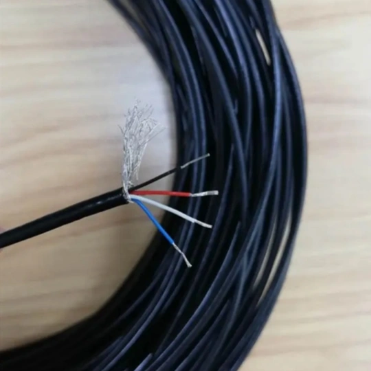
4. Select Insulation, Shielding & Jacket
The cable’s construction—from the inner insulator to the outer jacket—determines its performance in harsh industrial environments.
Layering Your Cable:
- Insulation (Inner Dielectric):Separates conductors.
- PVC:Cost-effective, general-purpose (-55°C to +105°C).
- PE:Low capacitance, good for high-speed data, but less flexible.
- XLPE:Higher temperature rating, common in power cables.
- PTFE/Teflon:Excellent for high-temp and chemical resistance.
- Silicone:Very high flexibility and heat resistance (up to 180°C).
- Shielding:Critical for data integrity and EMI immunity.
- Foil (Aluminum/Polyester):Provides 100% coverage but less flexible.
- Braided Shield (Tinned Copper):Excellent flexibility and easier grounding. Often used in combination with foil (e.g., “foil + 85% braid”).
- Serve or Spiral Wrap:A lighter option for moderate EMI environments.
- Jacket (Outer Sheath):The first line of defense against the environment.
- PVC:General-purpose, oil and abrasion resistant.
- PUR:High flexibility, excellent abrasion and chemical resistance. Common in drag chains.
- TPE/TPU:Good flexibility and broad chemical resistance.
- Rubber (Neoprene, CPE):For heavy-duty, oil-resistant, and flame-retardant needs.
- LSZH (Low Smoke Zero Halogen):For fire safety in public spaces and ships.
Pro Tip:For oily or chemical-heavy environments, ask for data on oil, fuel, and chemical resistance, not just a general claim of “oil resistant”.
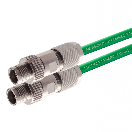
🔌 5. Select Connectors & Terminations
Connector failures are a leading cause of field issues. A robust connector is as critical as the cable itself.
Connector Selection Criteria:
- Mechanical Fit:Match the connector to the mating part using the correct series, pin count, gender, and keying/polarization.
- Current & Voltage Rating:Ensure the connector’s contacts and housing are rated for your application with an appropriate safety margin.
- Environmental Rating:Choose based on the operating temperature and the required IP rating(e.g., IP65, IP67, IP68) for dust and water ingress.
- EMI Protection:Opt for metal-shell connectors with shielded cable clamps for noisy environments. Ensure the shield is bonded to the connector shell.
- Mating Cycles:For frequently connected/disconnected applications, specify a high mating cycle rating (e.g., >500 or >1000 cycles).
- Termination Method:Crimping is standard for reliability. Soldering is an alternative, and IDC is used for some multi-pin connectors.
Pro Tip:Always request a pinout drawingand wiring schematic from your manufacturer to avoid on-site confusion.
6. Plan for Flexing, Routing & Mechanical Stress
Industrial environments are physically demanding. Cables must withstand constant movement and tight bends without failing.
Key Mechanical Considerations:
- Bend Radius:Specify both static and dynamic bend radii. A common design rule is a minimum bend radius of 6–10 times the cable diameter. Tighter bends require high-flex cables.
- Flex Life:For cables in drag chains or robots, request data on flex cycles (e.g., >1 million). Finer stranding and PUR jackets are typical solutions.
- Tensile Strength & Pulling Force:For long cable runs, specify the maximum tensile load and use a pulling eye or swivel.
- Strain Relief:Use molded boots, backshells, or clamps at both ends to transfer stress from the solder joints to the cable body.
- Vibration & Shock:Choose connectors with locking mechanisms and robust strain relief. Consider braided shields or additional support for high-vibration applications.
Pro Tip:If your cable will be in a drag chain, provide the chain length, bend radius, and travel speedto your manufacturer.
7. Review Manufacturing Feasibility (DFM)
A design that looks good on paper may be costly or impossible to manufacture consistently. A Design for Manufacturability (DFM) review is essential.
DFM Checklist:
- Tooling Availability:Confirm that your chosen connector series is in the manufacturer’s standard tooling library to avoid high NRE costs.
- Cable Geometry:Ensure the overall diameter and bend radius are compatible with the chosen connector and tooling.
- Process Complexity:Highly complex assemblies with many small wires and tight tolerances may require manual assembly, increasing cost and lead time.
- Testing & Traceability:Define required tests (continuity, hipot, etc.) and establish a system for lot traceability and quality documentation.
Pro Tip:Before finalizing the design, ask for a DFM review and a prototype. This step often reveals small changes that can save significant costs in mass production.
8. Define Testing, Quality & Compliance
A professional approach to testing ensures your custom industrial cable assembly performs reliably in the field.
Testing & Quality Essentials:
- Electrical Tests:Continuity, insulation resistance, and high-potential (hipot) testing are standard. High-speed data cables may require impedance and time-domain reflectometry (TDR) tests.
- Mechanical Tests:Perform tensile pull tests and bend-cycle tests to validate the flex life.
- Environmental Tests:Simulate real-world conditions with thermal cycling, UV exposure, and immersion tests if required.
- Certifications:Ensure the manufacturer’s processes and materials meet relevant standards like ISO 9001, UL, CSA, RoHS, and REACH.
Pro Tip:For critical projects, request a test reportwith each batch, including lot number, test parameters, and pass/fail results.
9. Plan for Labeling, Packaging & Logistics
Details like labeling and packaging are often overlooked but are crucial for efficient installation and maintenance in the field.
Final Touches:
- Cable Marking:Use heat-shrink sleeves, inkjet printing, or laser marking for part numbers, length, and date codes.
- Connector Marking:Clearly label pin 1 or use color codes.
- Packaging:Use static-shielding or moisture-barrier bags for sensitive components. For large orders, request custom lengths to be pre-cut and kitted.
- Documentation:Ensure you receive updated drawings, BOMs, test reports, and compliance certificates.
Quick-Start Spec Sheet
Use this template to gather your requirements before contacting a manufacturer. Providing this information will streamline the quoting process and reduce errors.
text
Application: __________________________________________
Installation: ________________________________________
Environment: Temp range ____°C, IP, UV? ___, Oil? ___
Voltage: Operating ______V, Peak ______V
Current per Conductor: ______A
Signal Type: Power / Control / Data / Hybrid
Data Rate / Frequency: _______________________________
Shielding: Overall / Pair / None, Required EMI performance ______
Conductor: Material ______, Stranding ______, AWG/mm² ______
Insulation: Material ______, Temp rating ______°C
Jacket: Material ______, Color ______, Oil/Chem resistance ______
Connector 1: Series ______, Pins ______, Gender ____, IP
Connector 2: Series ______, Pins ______, Gender ____, IP
Mechanical: Bend radius ______D, Flex life ______ cycles
Special Features: Strain relief ______, Overmolding ______, Armor ______
Compliance: UL / CSA / RoHS / REACH / Other ______
Testing: Hipot ______V, Continuity, Other ______
Quantity / Lead Time: _______________________________
Conclusion: Engineering for Performance, Not Just Price
Customizing industrial cable assemblies is a systems-engineering task. The most reliable cables are not the cheapest, but those whose application, electrical, mechanical, and environmental parameters are clearly defined and validated.
By following this guide, you can create a specification that leads to a robust, long-life cable assembly. Partnering with an experienced manufacturer for early DFM reviews and prototype testing is a strategic investment that reduces risk and total cost of ownership.
When your industrial systems demand peak performance, a well-engineered custom cable assembly is not an accessory—it is a critical component of your product’s reliability and your company’s reputation.