Anti-Interference Micro Coaxial Cable for Automotive ADAS
High-speed sensor links in modern vehicles—from surround-view cameras to radar and satellite navigation—demand miniature interconnects that preserve signal integrity under harsh EMI/EMC and environmental conditions. This guide explains how to select, design, and integrate anti-interference micro coaxial cable assemblies for ADAS, with practical parameter targets, connector ecosystems, EMI mitigation techniques, and validation steps aligned to automotive requirements.
Why Micro Coax Is Central to ADAS Signal Integrity
Micro coaxial cables are purpose-built for high-frequency, high-bandwidth, and densely packed environments. In vehicles, they carry high-speed video and RF signals between cameras, antennas, radars, and domain controllers. Their coaxial geometry confines the electric and magnetic fields, inherently suppressing electromagnetic interference and crosstalk. Typical automotive micro-coax outer diameters range from about 0.3 mm to 1.0 mm, enabling routing through tight spaces while maintaining controlled impedance and shielding. These characteristics make micro coax a preferred medium for GMSL2, FPD-Link III, HMOS, HLED, and other high-speed camera links, as well as GPS/GNSSand certain RF modules in ADAS platforms
Connector Ecosystem and Frequency Targets
Modern ADAS designs have moved toward miniaturized RF interconnects to save space and improve assembly automation. The table below summarizes common automotive micro-coax connector families and their typical use cases:
Connector Family
Typical Use
Frequency/Data Rate
Space Claim vs. FAKRA
Notes
FAKRA
Legacy camera/RF links
Up to 6 GHz
Baseline
Color-coded keying, widely deployed
Mini‑FAKRA / MCA
High-speed camera/RF
Up to 15–20 GHz
Up to 80%smaller
Modular ports, supports automation
HFM (Rosenberger)
High-density camera links
Up to 20 GHz
~80%smaller
1×, 2×, 4× port variants, waterproof options
U.FL (IPEX/UMCC)
Board‑to‑antenna, IoT
Up to 6 GHz
Ultra‑low profile
Common in Wi‑Fi/BT/GPS modules; limited mating cycles
Connector choice directly determines the usable bandwidth, EMI robustness, and serviceability of the link. For new platforms, Mini‑FAKRA/MCA or HFM are preferred for high‑speed video and RF, while FAKRA remains for backward compatibility
Designing Anti‑Interference Micro Coax for Harsh Automotive Environments
•Characteristic Impedance and Return LossTarget 50 Ωsingle-ended (or 100 Ωdifferential for LVDS/serial links) with tight tolerance. Ensure return loss and impedance consistency over the operating frequency to minimize reflections and eye‑diagram closure. Use materials and geometries that control dielectric loss and geometry stability.
•Shielding ArchitectureDual‑shield (aluminum foil + braid) or tri‑shield constructions are common. Aim for high shielding effectiveness (SE) to suppress both incident EMI and cable‑to‑cable coupling. In dense harnesses, individual shielding of each micro‑coax reduces NEXT/FEXTand preserves channel isolation.
•Dielectric and Loss ControlLow‑loss dielectrics (e.g., foamed PTFE/PFA) reduce attenuation at high frequencies. For ultra‑fine cables, uniform cell size in foamed insulation and process control are critical to maintaining consistent effective dielectric constant (εeff) and minimizing local variations that cause dispersion and loss.
•Mechanical Robustness and Flex LifeDefine minimum bend radius (commonly 5–10× OD) and flex life targets consistent with door/hood/trunk routing. Use stranded inner conductors and rugged jacketing (e.g., PVC, PE, LSZH) to survive vibration, temperature, and oil/fluid exposure.
•EMI Mitigation Best Practices
•Maintain continuous shield continuity through connectors; use board‑mounted ground vias and chassis grounds to control ground loops.
•Separate high‑speed video/RF from switching power and motor drive harnesses; consider twisted‑pair or shielded twisted‑pair for non‑critical links to reduce aggregate noise.
•Apply connector‑to‑cable strain relief and avoid routing micro‑coax parallel to noisy edges or apertures.
•Use common‑mode chokes or baluns where differential links interface with long unshielded paths.
These principles—shielding, controlled impedance, low‑loss dielectrics, and robust mechanics—are foundational to anti‑interference performance in micro‑coax for ADAS
Example Parameter Targets for Common ADAS Links
Use Case
Typical Cable
Connector
Key Electrical Targets
Surround‑view / DMS (GMSL2)
Shielded micro‑coax, 50 Ω
FAKRA or Mini‑FAKRA/HFM
Up to 4 Gbpsper channel; low‑loss routing; robust EMI; PoCsupport common
Front/Rear View (FPD‑Link III)
Shielded micro‑coax, 50 Ω
FAKRA
2 Gbpsclass links; stable skew; low return loss
GNSS / Sharkfin Antenna
Ultra‑fine coax (1.13/1.32 mm), 50 Ω
U.FL / FME
Up to 6 GHz; low insertion loss; strain relief critical
Radar Module IF/LO (internal)
Micro‑coax 0.3–0.5 mmOD
Board‑mount coax connectors
High‑frequency integrity; low loss; mechanical flex control for serviceability
These targets reflect common industry practices for high‑speed video and RF interconnects in vehicles. Always correlate electrical budgets with harness length, connector loss, and system‑level EMC margins
Routing, Assembly, and EMI Validation
•Harness Topology and SeparationRoute high‑speed micro‑coax away from high‑dv/dt switching nodes and power cables. Maintain separation or use grounded shielding partitions in multi‑branch harnesses. Avoid tight bundling with unshielded sensor or actuator wires.
•Connector and Crimp QualityVerify connector‑to‑cable shield termination (360° coverage), consistent crimp geometry, and strain relief. Poor terminations are a leading cause of EMI ingress and intermittent failures.
•EMC and Environmental TestingPerform radiated/conducted emissions and immunity per automotive standards (ISO 11452, ISO 10605, CISPR 25). Validate IP6xsealing where applicable (e.g., HFM waterproof variants). Subject cables to temperature cycling, vibration, and fluid exposureper ISO 16750profiles.
•Signal Integrity ValidationFor video links, measure eye diagrams, jitter, and BER under worst‑case supply and temperature conditions. For RF links, measure S‑parameters(S11/S21) and shielding effectiveness. Include connector‑level characterization to de‑embed fixture effects.
•Serviceability and LifecycleDefine mating cycles and retention forces appropriate for the connector family. For U.FL, limit mating/unmating to avoid wear; for automotive‑grade Mini‑FAKRA/HFM, follow OEM‑specified cycle and locking features311.
When to Choose Micro Coax vs. Alternatives
•Choose micro coax when you need:
•High bandwidthwith tight impedance controlin a small diameter.
•Superior EMI isolationfor dense harnesses or noisy environments.
•Deterministic, low‑latencylinks for video or RF.
•Consider alternatives when:
•Cost and routing simplicity outweigh high‑speed demands (e.g., shielded twisted‑pair for lower‑rate control/data).
•Extreme flexibility and ultra‑low profile are needed for board‑to‑board jumps (e.g., flex or twin‑ax in some architectures).
•Legacy infrastructure dominates and re‑design cost is prohibitive (FAKRA‑based systems).
Conclusion
Anti‑interference micro coaxial cable assemblies are a cornerstone of reliable, high‑speed signal chains in automotive ADAS. By combining the right connector family (FAKRA, Mini‑FAKRA/MCA, HFM, or U.FL), controlling impedance and shielding, and following automotive EMI and environmental practices, engineers can achieve the bandwidth, robustness, and serviceability that modern vehicles demand. Whether you are specifying GMSL2camera links, FPD‑Link IIIvideo, GNSSfeeds, or radar IF/LO interconnects, grounding the design in these principles will ensure stable performance from prototyping through production and lifetime operation
Corrosion-Resistant Cable Connectors: Reliable Connectivity for Harsh Environments
Ensure uninterrupted performance in the toughest conditions with our corrosion-resistant cable connectors. Designed for durability and longevity, these.
Product OverviewQuick-Install Cable Adapters are the game-changing connectivity solution designed for professionals and DIY enthusiasts alike. Engineered to eliminate installation hassles, these adapters provide instant, tool-free conne.
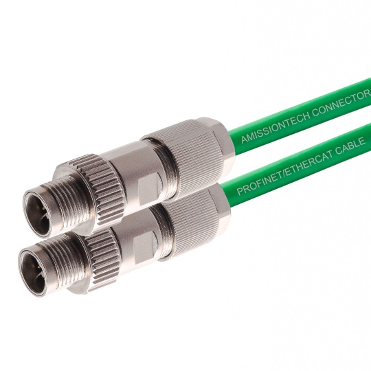
Industrial cable components are the backbone of reliable and efficient connectivity in industrial automation, robotics, and machinery. Engineered to withstand harsh environments while ensuring seamless data transmission and power delivery.
Heavy machinery cable assemblies are robust, high-performance connectivity solutions engineered to meet the demanding requirements of industrial and heavy-duty applications. Designed for durability, reliability, and optimal performance in.
Industrial Cable Assembly Product Summary
Material & Safety
Utilizes premium raw materials and globally recognized components (e.g., ABB, TE Connectivity) ensuring high reliability and safety to prevent risks like fire and e.
In today’s technology-driven world, maintaining uninterrupted signal integrity is critical for industrial, commercial, and residential applications. The Shielded Cable Core is engineered to deliver superior electromagnetic interference .
Meta Description: Discover high-performance industrial control cable module components designed for seamless automation, harsh environments, and superior connectivity. Explore specs, certifications, and applications.
H2: Industrial Con.
Meta Description: Discover the ultimate Protective Cable Kit designed to safeguard your cables from wear, tangles, and damage. Perfect for home, office, and industrial use. Shop now for long-lasting cable management!
Protecti.
When it comes to electrical systems operating under extreme mechanical and electrical stress, high-load cable terminations are critical components that ensure seamless power transmission, safety, and system longevity. Engineered to .
Ensure reliable power transmission and long-lasting performance in the harshest conditions with our High-Temperature Resistant Cable Accessories. Engineered to withstand extreme heat, these premium-grade accessories are designed to prote.