Signal crosstalk – unwanted signal coupling between adjacent wires – wreaks havoc in industrial automation, causing data errors, measurement inaccuracies, and erratic equipment behavior. Here’s how to prevent it in your multi-conductor cable assemblies:
- Implement Proper Shielding:
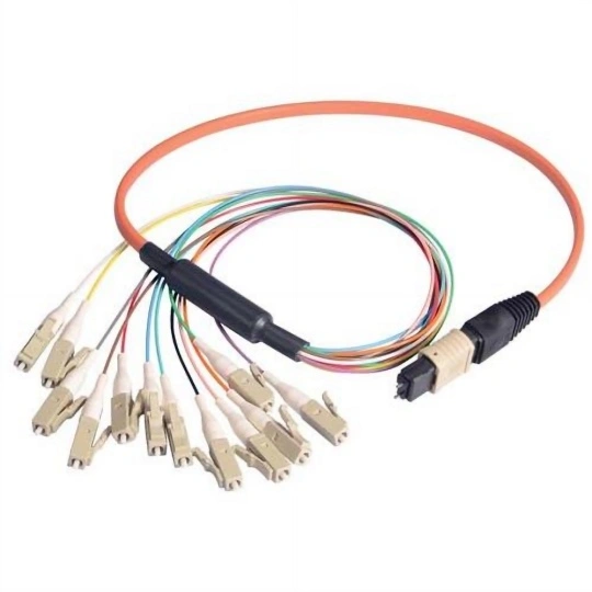
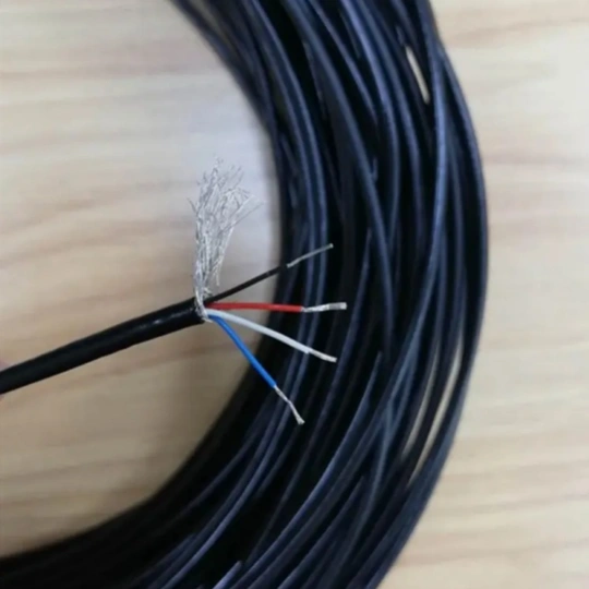
- Use Shielded Cables: Choose cables with overall shields (foil and/or braid) and/or individually shielded pairs/twisted pairs (STP). This is crucial for sensitive signals like analog sensors or comms.
- Choose the Right Shield: Foil shields offer excellent coverage against high-frequency noise. Braid shields provide better mechanical strength and lower-frequency noise protection. Combined shields offer the best overall performance.
- Ground Shields Correctly: This is critical. Shields must be grounded effectively at one end only (usually the control panel end) to prevent ground loops. Use a dedicated, low-impedance grounding conductor or clamp. Never “pigtail” shields.
- Utilize Twisted Pair Construction:
- Use cables where signal and return wires (like +/- analog or RS-485 data pairs) are tightly twisted together. Twisting minimizes the loop area for induced magnetic fields, significantly reducing inductive crosstalk and noise pickup. Pair symmetry is vital.
- Employ Differential Signaling:
- Where possible (e.g., RS-485, Ethernet, some analog I/O), use signals transmitted differentially (over two wires, 180 degrees out of phase). Differential receivers cancel out noise or crosstalk common to both wires. This greatly improves noise immunity.
- Maintain Proper Separation:
- Within Cable Assemblies: Bundle wires carrying different signal types separately within the cable harness. Keep high-voltage AC power, motor drives, sensitive analog signals (thermocouples, mV sensors), and digital communication wires (Ethernet, RS-485) in distinct, shielded bundles or separate compartments within the cable.
- During Installation: Route sensitive signal cables physically away from power cables, variable frequency drives (VFDs), and other major noise sources. Maintain at least 6-12 inches (or more) of separation. If they must cross, do so at right angles.
- Consider Cable Selection & Routing:
- Choose the Right Cable Type: Don’t mix incompatible signal types within a single unshielded multi-conductor cable. Use specialized instrumentation cables for low-level signals.
- Avoid Parallel Runs: Never run sensitive signal cables tightly parallel to high-noise cables for long distances. Cross-talk increases significantly with parallel length.
- Optimize Termination & Grounding:
- Terminate Properly: Ensure signals are correctly terminated according to protocol specifications (e.g., RS-485 termination resistors) to prevent signal reflections that can exacerbate interference.
- Single-Point Ground: Ground all cable shields, equipment chassis, and power supplies at a single, clean, low-impedance ground point (“star point”) within the control panel. Avoid creating multiple ground paths that can form noisy loops. Use appropriately sized grounding conductors.
- Isolate Signal Grounds (Where Appropriate): For very sensitive DC analog signals (e.g., < 50mV), consider isolated transmitters/inputs to break ground loops and prevent common-mode noise.
- Follow Good Installation Practices:
- Ensure shield continuity throughout connectors (use backshells or shielded connectors).
- Maintain cable bend radius to avoid damaging shields or internal geometry.
- Use cable ties correctly – tight enough to support, not so tight as to deform cables or shields. Avoid metallic ties near sensitive cables.
- Securely anchor cables to prevent vibration that can wear insulation.
Key Takeaway: Preventing crosstalk requires a system-wide approach focusing on shielding, twisting, separation, and proper grounding/termination. Implementing these practical steps consistently will drastically improve signal integrity and reliability in your demanding industrial environments.