
Industrial Cable Assemblies-Industrial Cable Assemblies factory
Intermittent signal loss is one of the most frustrating issues plaguing industrial CAN bus systems. Unlike permanent faults, these elusive glitches disappear during testing, only to reappear under specific conditions, halting production and causing headaches. Diagnosing them effectively requires a targeted approach. Here’s a practical step-by-step guide:
1. Recognize the Signs (The Intermittent Red Flags):
* Erratic Device Communication: Nodes dropping offline randomly, reappearing spontaneously.
* Sporadic Error Frames: Increased error counters (ERR_CNT in diagnostics tools) without a consistent pattern.
* Inconsistent Data: Missing sensor readings, actuator commands failing briefly.
* Symptoms Worse Under Specific Conditions: Higher temperatures, machinery vibration, cable movement, or humidity changes trigger the issue.
2. Isolate the Problem Area:
* Check Network Status: Use a CAN bus analyzer or diagnostic software to monitor the entire network. Look for spikes in error frames correlating with communication loss.
* Divide and Conquer: Temporarily disconnect sections of the network or individual nodes. Does the problem disappear when a specific segment or device is removed? If possible, temporarily substitute suspect cable segments with known-good cables.
3. Perform a Thorough Physical Inspection:
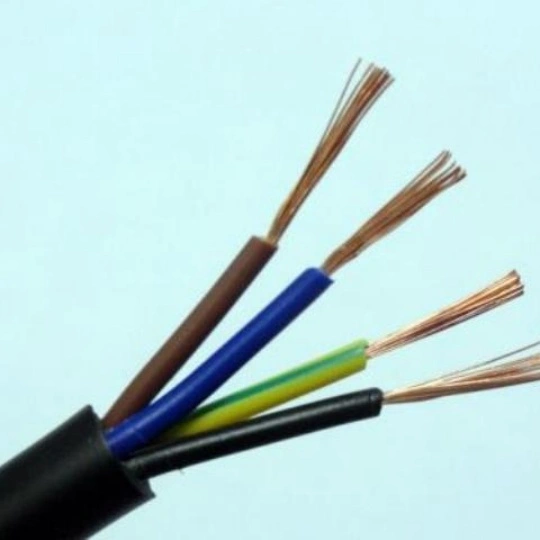
* Visual Cable Inspection: Examine the entire length of suspect cables meticulously. Look for:
* Abrasion: Scrapes or cuts on the outer jacket, especially near clamps, sharp edges, or moving parts.
* Kinks or Sharp Bends: Tight bends exceeding the cable’s minimum bend radius.
* Pinching or Crushing: Flattened sections where cables run through conduits or under heavy objects.
* Damage at Connectors: Strain relief pulled out, bent pins, cracked connector bodies, corrosion (due to moisture ingress). Pay close attention to where cables enter connectors – a common failure point.
* Environmental Damage: Signs of chemical exposure (swelling, discoloration), excessive heat (melted jacket), or rodent damage.
* Inspect All Connections: Reseat every connector on the affected segment firmly. Look for loose terminal screws, improperly crimped wires, or damaged pins/sockets.
4. Test Cable and Connector Integrity:
* Continuity Test: Use a high-quality multimeter to check continuity (low resistance, typically less than 1-2 ohms per conductor) for CAN_H, CAN_L, and Shield/Ground between both ends of the suspect cable assembly while gently manipulating it. Move, bend, and twist the cable along its length during testing. A break in continuity during manipulation is a sure sign. Note: This test won’t find subtle impedance changes.
* Short Circuit Test: Check for unintended shorts between CAN_H and CAN_L, CAN_H and Ground, CAN_L and Ground, and any shield-to-signal shorts. Test during cable manipulation as well.
* Shield Integrity: Ensure the cable shield is properly terminated (single-point grounded at one end only, usually at the power supply) and shows continuity from connector shell to connector shell along the segment. A broken or poorly grounded shield invites noise interference.
5. Check CAN Bus Termination:
* Verify that exactly two 120-ohm resistors are present – one at each physical end of the main trunk line. Use an ohmmeter on the disconnected main trunk: it should read approximately 60 ohms (two 120-ohm resistors in parallel). Incorrect termination (missing, wrong value, wrong placement) causes signal reflections leading to intermittent errors, especially at higher baud rates or long lengths.
6. Evaluate Network Topology & Environment:
* Excessive Drop Lines: Ensure spur lines (drop cables to devices) are short (typically < 0.3 meters for 1 Mbps systems). Long spurs create impedance mismatches and reflection points. Use a star coupler/hub if long drops are unavoidable.
* Total Cable Length: Confirm the total network length is within limits for your baud rate (e.g., ~40m max at 1 Mbps, ~500m at 125 kbps).
* Noise Sources: Are high-voltage cables, variable frequency drives (VFDs), motors, or noisy power supplies running parallel and close to CAN cables? Can you temporarily reroute the CAN cable away from suspected noise sources as a test? If interference is suspected, ensure shield termination is correct. Ferrite beads on cable ends near connectors can sometimes help mitigate high-frequency noise.
What to Do When You Find the Culprit:
Prevention is Key:
By systematically applying these diagnosis steps, you can pinpoint the source of frustrating intermittent CAN bus signal loss, most often related to the cables or connectors themselves, and restore reliable communication on your industrial network.
Our factory offers high-quality products at competitive prices
Meta Description: Discover the ultimate Protective Cable Kit designed to safeguard your cables from wear, tangles, and damage. Perfect for home, office, and industrial use. Shop now for long-lasting cable management! Protecti.
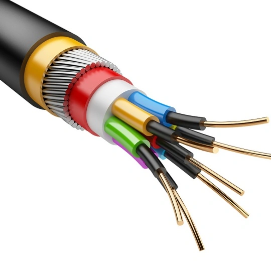
In today’s technology-driven world, maintaining uninterrupted signal integrity is critical for industrial, commercial, and residential applications. The Shielded Cable Core is engineered to deliver superior electromagnetic interference .
Feel free to reach out to us for any inquiries or orders.