Industrial Cable Assemblies-Industrial Cable Assemblies factory
Selecting the right RF (Radio Frequency) cable assembly is critical for ensuring optimal performance in wireless communication systems, aerospace applications, medical devices, and countless other industries. With so many options available, choosing the best RF cable assembly can be overwhelming. This guide will walk you through the key factors to consider, ensuring your selection aligns with your technical requirements, budget, and application needs.
1. Understand Your Frequency Range
RF cable assemblies are designed to operate within specific frequency ranges. Frequency compatibility is the first factor to evaluate:
Pro Tip: Always choose a cable rated for a frequency range higher than your maximum operating frequency to account for unexpected spikes.
Impedance mismatches can lead to signal reflections, degraded performance, and even equipment damage. Most RF systems use 50-ohm impedance (common in telecom and aerospace) or 75-ohm impedance (typical in video broadcasting).
Two critical performance metrics for RF cables are insertion loss (signal loss over length) and Voltage Standing Wave Ratio (VSWR) (measure of signal reflection):
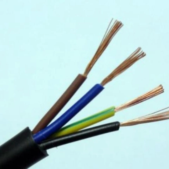
Material matters: Cables with foam polyethylene insulation or air-spaced designs typically offer lower loss than solid dielectric cables.
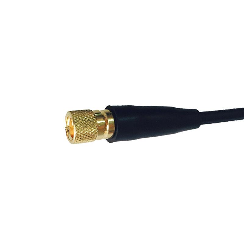
Connectors must be compatible with your equipment and environment:
Durability: For harsh environments, select connectors with gold plating (corrosion-resistant) or stainless-steel housings.
Environmental factors can degrade performance:
While high-performance cables like phase-stable or ultra-low-loss variants are expensive, they’re essential for mission-critical applications. For less demanding uses (e.g., short-range Wi-Fi), budget-friendly RG cables may suffice.
Compliance with industry standards.
Frequency range and bandwidth requirements.
Impedance (50Ω vs. 75Ω).
Insertion loss and VSWR limits.
Connector type and durability.
Environmental resilience.
Our factory offers high-quality products at competitive prices
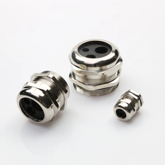
Corrosion-Resistant Cable Connectors: Reliable Connectivity for Harsh Environments Ensure uninterrupted performance in the toughest conditions with our corrosion-resistant cable connectors. Designed for durability and longevity, these.
Meta Description: Discover the ultimate Protective Cable Kit designed to safeguard your cables from wear, tangles, and damage. Perfect for home, office, and industrial use. Shop now for long-lasting cable management! Protecti.
Feel free to reach out to us for any inquiries or orders.