How to Ensure EMI/RFI Shielding in Industrial Cable Assemblies for Da...
Electromagnetic Interference (EMI) and Radio Frequency Interference (RFI) are pervasive threats to data center integrity. Industrial-grade cable assemblies operating within these high-density, high-power environments are particularly vulnerable. Inadequate shielding can lead to corrupted data transmission, intermittent connectivity, system slowdowns, and catastrophic failures – unacceptable risks for mission-critical operations. Implementing robust EMI/RFI shielding in industrial data center cables is non-negotiable.
1. Select the Right Shielding Type and Construction:
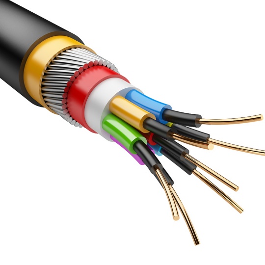
- Braided Shields (e.g., Tinned Copper): Offer excellent flexibility, durability, and high-frequency shielding effectiveness (typically 70-95% coverage). Ideal for cables needing repeated flexing or routed through tight spaces in racks and trays. Provides good physical protection.
- Foil Shields (e.g., Aluminum/Polyester Laminate): Provide 100% coverage against high-frequency interference and are cost-effective. Best suited for stationary cables or as part of a composite shield. Less robust mechanically than braid.
- Combination Shields (e.g., Foil + Braid): Offer the best of both worlds: 100% coverage from the foil combined with the durability, flexibility, and low-frequency shielding effectiveness of the braid. This is often the gold standard for industrial data center cables handling sensitive or high-speed signals.
- Spiral Shields (Less Common): Primarily used for ultra-flexible applications but offer lower shielding effectiveness compared to braid and are more susceptible to deformation.
- Shield Coverage Percentage: Higher coverage generally equates to better shielding. Aim for braid coverage >80% for critical applications. Foil inherently provides 100% coverage.
2. Ensure Unbroken Shielding Continuity:
- Termination is Paramount: The shield must maintain a 360-degree, low-resistance connection to the connector shell or grounding point. Any gap creates an antenna, radiating or receiving interference.
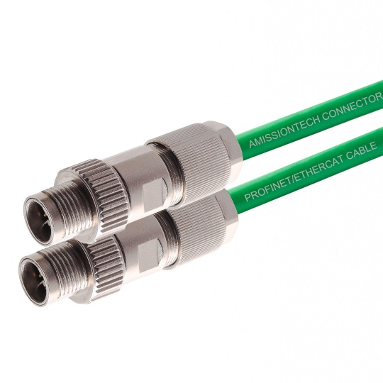
- Effective Connector Interface: Use connectors specifically designed for shielded cables. Features like metal backshells, conductive gaskets, clamp-style strain reliefs, or crimp/solder cups are essential for terminating the shield effectively.
- Shield Drain Wires: While common, ensure drain wires are properly secured and bonded to the connector’s ground with minimal lead length. Long drain wires act as antennas. A robust clamp or crimp directly connecting the braid/foil to the connector shell is superior.
- markdown复制
**EMI Connector Backshells:** Utilize metal backshells that clamp securely around the cable jacket and connect electrically to both the cable shield and the connector shell, ensuring continuous coverage. Conductive tape at the jacket entry point can enhance the seal.
3. Implement Strict Grounding Best Practices:
- Single-Point Grounding: Ground the cable shield at one end only, typically at the source equipment rack. Grounding at both ends creates ground loops, which are major conduits for low-frequency EMI (like 50/60Hz hum) and can worsen interference. Exceptions exist for very high-frequency applications (often above 1 MHz) or specific system designs, but single-point grounding is the standard rule for data center analog and digital signals.
- Low-Impedance Ground Path: The connection between the shield and the ground point must be as short, direct, and low-resistance as possible. Use wide, flat braids or straps if needed.
- Proper Rack and Cabinet Grounding: Ensure the entire rack or cabinet structure provides a solid, low-impedance earth ground reference point. Star grounding is ideal for minimizing ground loop potential within the cabinet.
4. Consider Cable Construction and Materials:
- Transfer Impedance (ZT): This is the key metric for shield effectiveness. Lower ZT means better shielding. Industrial cables should specify ZT values (e.g., measured per IEC 62153-4-3). Combination shields generally achieve lower ZT than single-layer shields.
- Jacket Material: Durable jackets resistant to abrasion, chemicals, oils, and UV (if applicable) are crucial for industrial settings. A damaged jacket can expose or compromise the underlying shield. Consider robust materials like PUR (Polyurethane) or PVC blends designed for harsh environments.
- Twisted Pair Construction: For balanced data cables (e.g., Cat6A, Cat8, Twinax), tightly twisted pairs are fundamental. Twisting provides inherent noise cancellation (common-mode rejection), working synergistically with the shield to protect signal integrity.
5. Proper Cable Routing and Separation:
- Segregation of Power and Data: Maintain strict physical separation between high-power cables (AC power feeds, motor drives) and sensitive data/communication cables. Follow specific separation guidelines (e.g., defined in inches/cm within data center design standards like ANSI/TIA-942). Minimum recommended separation is often 12-24 inches.
- Cable Trays and Conduit: Use dedicated trays or separate compartments for different cable classes. Metal trays can offer some additional shielding if properly grounded, but segregation remains key.
- Crossing at Right Angles: When power and data cables must cross paths, ensure they do so at 90-degree angles to minimize the length of parallel runs where coupling occurs.
- Avoid Coiling Excess Cable: Excess cable coiled up can create inductive loops susceptible to magnetic field interference (MFI). Use appropriate cable lengths and manage slack properly in service loops.
6. Rigorous Testing and Verification:
- Factory Testing: Specify shielding effectiveness testing on cable assemblies during manufacturing. Tests like MIL-STD-461, IEEE 299, or IEC 62153-4-3 provide quantitative measures. Insist on test reports.
- Transfer Impedance Measurement: For critical links, specifying ZT measurements per IEC 62153-4-3 provides the most accurate assessment of shield performance under real-world conditions.
- Continuity Testing: Verify electrical continuity of the shield along the entire cable assembly from connector to connector before installation.
- Post-Installation Verification: Utilize diagnostic tools like Time Domain Reflectometers (TDR) or specialized EMI scanners during commissioning and maintenance to identify unexpected interference sources or shield integrity issues. Conduct bit error rate tests (BERT) on high-speed links.
7. Adherence to Standards:
Comply with relevant industry standards governing EMI/RFI performance and cabling in data centers:
- EMC Standards: FCC Part 15 (US), CISPR 32 (International), EN 55032/55035 (EU), MIL-STD-461 (for defense applications).
- Cabling Standards: ANSI/TIA-568 (especially guidelines for separation), ISO/IEC 11801, ANSI/TIA-942 (Data Center Standard), relevant IEC standards (e.g., IEC 60603-7 for connectors, IEC 62153 for transfer impedance).
- Safety Standards: UL, CSA, CE marking (including EMC directive).
Conclusion:
Ensuring EMI/RFI shielding in industrial cable assemblies for data centers is a multi-layered challenge demanding attention to material selection, termination integrity, rigorous grounding practices, proper installation, and thorough testing. Neglecting any aspect can compromise the entire electromagnetic defense of sensitive data links. By adhering to best practices in shield construction, connector interface design, grounding topology, cable management, and stringent validation through standards and testing, industrial-grade cable assemblies can deliver the essential noise immunity required for reliable, high-performance data center operation in electrically demanding environments. The investment in robust shielding translates directly to reduced downtime and secured data integrity.


